
Optimal Coordinated Control of DC Microgrid Based on Hybrid PSO–GWO Algorithm †


1
Department of Electrical and Electronic Engineering, Auckland University of Technology, Auckland 1010, New Zealand
2
Department of Energy Technology, Aalborg University, 9220 Aalborg, Denmark
*
Author to whom correspondence should be addressed.
†
This paper is an extended version of our paper published in Al-Tameemi, Z.H.A.; Lie, T.T.; Foo, G.; Blaabjerg, F. Optimal Power Sharing in DC Microgrid under Load and Generation Uncertainties Based on GWO Algorithm. In Proceedings of the 2021 IEEE PES Innovative Smart Grid Technologies—Asia (ISGT Asia), Brisbane, Australia, 5–8 December 2021.
Electricity 2022, 3(3), 346-364; https://doi.org/10.3390/electricity3030019
Submission received: 29 June 2022
/
Revised: 24 July 2022
/
Accepted: 4 August 2022
/
Published: 8 August 2022
(This article belongs to the Collection Optimal Operation and Planning of Smart Power Distribution Networks)
Abstract
:Microgrids (MGs) are capable of playing an important role in the future of intelligent energy systems. This can be achieved by allowing the effective and seamless integration of distributed energy resources (DERs) loads, besides energy-storage systems (ESS) in the local area, so they are gaining attraction worldwide. In this regard, a DC MG is an economical, flexible, and dependable solution requiring a trustworthy control structure such as a hierarchical control strategy to be appropriately coordinated and used to electrify remote areas. Two control layers are involved in the hierarchy control strategy, including local- and global-control levels. However, this research focuses mainly on the issues of DC MG’s local control layer under various load interruptions and power-production fluctuations, including inaccurate power-sharing among sources and unregulated DC-bus voltage of the microgrid, along with a high ripple of battery current. Therefore, this work suggests developing local control levels for the DC MG based on the hybrid particle swarm optimization/grey wolf optimizer (HPSO–GWO) algorithm to address these problems. The key results of the simulation studies reveal that the proposed control scheme has achieved significant improvement in terms of voltage adjustment and power distribution between photovoltaic (PV) and battery technologies accompanied by a supercapacitor, in comparison to the existing control scheme. Moreover, the settling time and overshoot/undershoot are minimized despite the tremendous load and generation variations, which proves the proposed method’s efficiency.
1. Introduction
Electrical energy is deemed as the fuel for today’s computerized world, and in the not-too-distant future, electricity scarcity will be a serious issue for many countries, especially in remote areas [1]. The distance from the central electrical grid system or the high cost of installing the grid line to such a distance are the primary reasons for the lack of electrification for the population in these areas [2]. Moreover, load demand is much lower in rural locations than in more populated ones. Therefore, using grid electricity is not the ideal option because of the transmission and regular maintenance expenditures. Furthermore, power outages, grid shutdowns, CO2 emissions, degradation of the ozone layer, biomass fuel reliance, and global warming, as summarized in Figure 1, have all contributed to a greater awareness of the need for safe, renewable, environmentally friendly, and clean energies. The direct integration of available renewable energy sources, involving photovoltaic (PV) and wind turbine generation (WTG), into the utility grid, is not easy due to their sporadic nature [3]. In this regard, the standalone MGs power system can combine such resources in one place as an excellent choice for isolated locations where grid power is unavailable [4]. In the literature, several categories of MGs, comprising AC, DC, and hybrid AC/DC MGs, have been employed to coordinate both renewable energy resources and energy storage systems to cater to required demand [5]. However, DC MGs are expanding more rapidly as compared to conventional AC MGs [6]. There are no harmonics or frequency conflicts, no synchronization is needed in the islanded mode, and no concerns about reactive power regulation exist [7,8]. In order to gain the full utilization of this type of microgrid, there are a few obstacles that need to be considered, including a seamless transition from islanded mode to on-grid mode operation, along with compatibility with AC loads [9]. Furthermore, microgrid protection is a problematic issue owing to the unavailability of zero-crossing current in addition to grounding [10,11]. The stability of the DC microgrid is a significant problem during fault circumstances, because of the resistive impedance characteristic of DC microgrid schemes and the absence of physical inertia [12]. Standardization seems to be another obstacle to the adoption of DC MGs [13]. Regardless of the abovementioned issues, DC MGs have a bright future owing to their improved compatibility with distributed renewable energy sources (DRES), better efficiency, and increased reliability [4]. It is essential to mention that power electronics converters are commonly employed as interfaces in each MG, to link each source to the shared bus [14].
Power electronics technology improvements have allowed DC electric grid schemes to achieve the criteria cost-effectively and smoothly [15]. With the advent of the DC MG approach, DC loads were widely used throughout different industries, including telecom facilities and data centers [16]. DC voltage rates are required for the operation of most modern electronic devices, including LED bulbs, phones/laptops chargers, and televisions. Therefore, DC MGs may address the rising demand in remote and tiny towns worldwide because of these qualities [17]. It is worth mentioning that the control of DC-bus voltage, besides power-sharing in the DC MGs, is a crucial aspect that scholars always need to be focused on [6]. Providing voltage support and efficient power distribution are the main challenges in a multi-source DC MG. In the literature, the conventional droop control approach of DC MGs has been used because it has simplicity in implementation due to the non-existence of a communication link [18]. This control strategy, nevertheless, results in inappropriate current distribution, voltage fluctuations, and circulating current regulation because of droop and line resistance amongst converters in an MG [4]. These converters must be properly managed to achieve an MG’s desired performance. In this regard, the DC MG has employed a hierarchical control method consisting of local and global control layers. In the first control layer of the MG, the primary control goals are determined to achieve adequate power and bus voltage stabilization within allowable constraints. Numerous control strategies have been put forth at the local control levels [14,15,16,17,18,19,20,21,22,23,24,25] to achieve these objectives. For realizing such objectives, there are various extensive studies on solving control issues in the local layers, especially droop control methods, including voltage/current, current/voltage, or voltage/power, which are often used to coordinate autonomously distributed units and manage the flow of power between load demand and generation [19,20,21]. The droop control approach is a popular decentralized approach for distributing power based on using virtual resistance. It is important to mention that power-sharing accuracy and voltage stability are intimately related to the droop coefficient of the system [22]. More specifically, as the droop coefficient increases, current sharing accuracy improves with an increase in voltage variations and vice versa [23]. This confirms that the selection of the droop coefficient value is the controller’s intrinsic trade-off. Although the key benefit of the droop control approach is that it eradicates the need for crucial communication links between parallel-connected converters since there are no communication links between parallel-connected converters, there is a lot of flexibility and reliability [24]. In contrast, there are several drawbacks to the conventional droop strategy: sluggish transient response, the intrinsic trade-off between voltage control and load sharing, line-impedance misalignment between parallel converters that impact active power-sharing, and unsatisfactory performance renewable resource [22,25]. Therefore, droop control is the subject of many related studies in the literature to enhance its performance. In [12], an adaptive droop method has been suggested to adjust the virtual resistance to follow the load current’s fluctuation across parallel-linked DC–DC converters. Owing to the sporadic nature of renewable resources (PV and WTG), energy storage systems (ESSs) consisting of batteries, supercapacitors (SCs), and ultracapacitors need to be included to overcome any load-generation mismatch that requires reliable control approaches to work effectively. Many control techniques to regulate power-sharing between supercapacitors and batteries have been discussed in the literature. In [26], state-of-charge feedback control is employed to ensure the battery’s charging level is within its allowable threshold, whereas the scheme of battery-energy storage (BES) is utilized to smooth out a wind farm’s production fluctuations. Combining the two into a hybrid electrical system is important because batteries have a higher power density and SCs have a high-power density. The batteries supply the main source of energy, and the SCs handle momentary load interruptions and power peaks during unforeseen circumstances [27,28,29]. Various control strategies have been proposed to enhance the performance, to keep the new hybridization system operating more efficiently. In [30], a novel control method has been presented based on the disconnection of low- and high-frequency power components of the hybrid battery/SCr energy supplier. The proposed technique leverages the battery current error component to control the SC. This method offers the advantages of faster voltage control and less battery-current stress. In [31], a new control approach is given to regulate power-sharing between batteries and SC and, therefore, keep MG voltage stability even with large energy-generation fluctuations. The authors of [32] concentrated on MG control schemes that involved PV, WTG, batteries, and SCs with hybrid AC/DC buses. The approach proposed a basic control technique for managing power between renewable resources and storage systems. It is noticed that the control methods used in local layers suffer from some issues under load disruptions and fluctuations of power generation because of dependency on classical proportional–integral (PI) controllers [33,34]. Under such conditions, these controllers do not provide satisfactory performance. Converters, on the other hand, are non-linear and time-variable systems [35]. Therefore, some attempts have been made to overcome such issues by replacing classical PI controllers with non-linear and advanced controllers. For instance, the authors in [27] adopted a proper control approach to reject the transient disturbance that results from the load current and limit the oscillations of the battery current. A new disturbance-rejection control approach based on a sole DC/DC converter has been devised for a hybrid battery/SCs system. The suggested control approach uses a super-twisting (STC) and PI controller in the internal and external voltage control loops. Furthermore, a Pulse Wave Modulator (PWM)-based sliding-mode control method is presented in [35] to adjust the voltage of the DC–DC boost converter. Although this method confirms its effectiveness in controlling the DC voltage, power-sharing has not been considered. In order to coordinate the power-sharing among renewable resources, battery packs, and load, the authors [36] developed a multilayered feed-forward artificial neural network (ANN)-based power management system (PMS). To realize the farthest utilization of the energy resources, while also controlling the voltage and power-sharing amongst hybrid renewable resources, a hybrid-modified Bat search algorithm/ANN control approach has been presented in [37]. The main issues with these methods are that hybrid energy storage systems have not been taken into account, so they may not be applied to experience high energy variations. Furthermore, ANN-based DC MG power management with a hybrid battery–SC energy system was proposed in [38,39] to accomplish a better voltage regulation besides well-organized power-sharing under various operating conditions, and the results were compared to the traditional control technique to confirm the superiority of the proposed approach. However, the proposed control strategy in [38,39] has not been examined simultaneously under extreme load changes and PV power fluctuations, to assess its effectiveness in such critical conditions in a real-life scenario. Moreover, the improvement of the droop control of the PV system and hybrid battery/SC control sides has not been explored. Furthermore, the authors of the aforementioned articles have not addressed the additional battery power provided to the simulated MG, which might possibly reduce its efficiency, especially in [38,39]. It has been discovered that there is a lack of focus on using meta-heuristic optimization approaches, which are featured because of their capability in addressing complex problems and optimizing controller parameters [34] to tackle the major challenges in the local control layer of DC MGs that have been discovered in earlier studies. These problems can be addressed using a variety of metaheuristic algorithms. A few examples of these algorithms are the ant lion algorithm, the PSO method, and the gravitational search algorithm. It is important to note that no single optimization algorithm can guarantee optimal system performance due to inherent strengths and drawbacks. As an illustration, PSO is characterized by its uncomplicated concept, relative resilience to control parameters, and computing efficiency; on the other hand, PSO’s restricted local/global search functionality causes it to get stuck in a local minimum when dealing with situations that are both highly constricted and highly robust [40]. Another example is the GWO algorithm, which has been demonstrated to outperform all the above mentioned algorithms [41]. Although GWO is featured by its speedy convergence, simplicity of implementation, and higher performance in uncertain and challenging search spaces, particularly in engineering applications [42], its delayed late-stage convergence and proneness to local optimality are major disadvantages [43,44]. There is no doubt that each of the two algorithms has a special search strategy. Their updating strategies guided by two or three agents leads to a reduction in variety, early convergence, or collapsing into the local optimum [45]. In order to address such issues, hybridization among algorithms has been proposed in previous studies to achieve a proper performance of the system. Hybrid PSO–GWO can be adopted to utilize the strengths of GWO and PSO. The primary goal of this hybridization is to enhance the capability of exploitation in PSO with the power of exploration in GWO [46]. As a result of this, this paper is focused on solving all of the problems depicted in Figure 1 using the hybrid PSO–GWO algorithm, which is characterized by its simplicity and ease of use as a tool to be used in successful execution, as well as completive performance, in comparison to those other optimization algorithms [47]. Using this algorithm to locate the global-best solution to an optimization problem has been shown to be effective [48], and this can boost the simulated MG’s local control layer’s performance. It is important to mention that improved power-sharing across paralleled DC–DC converters, improved MG voltage regulation within the specified level of 5%, reduced battery power losses, minimized settling time, and less overshoot/undershoot under diverse operating situations are significant contributions of the suggested technique. It is worth noting that this study is an extension of [49], with the new proposed approach achieving more consistent performance than [49]. For this study, a standard DC MG comprises several distributed energy resources (DERs), including a PV system and hybrid battery/supercapacitor, which are connected to a DC-bus by using boost and buck-boost converters, respectively, to support DC load in the system, as illustrated in Figure 2. It is important to mention that this microgrid is explained in detail in Section 2.
The structure of this article is as follows. DC MG control techniques, including traditional and new ones, are discussed in Section 2. In Section 3, HPSO–GWO is reviewed and formulated in order to address the problem under consideration. The graphic comparison of the significant outcomes of the traditional technique and the new control approach is shown in Section 4. A summary of what has been accomplished is provided in Section 5.
2. Modeling of the Local Control Layer in DCMG
2.1. DC MG Control
A typical MG incorporates several forms of distributed energy resources such as PV, WTG, and fuel cells accompanied by ESSs to deal with the intermittent nature of such sources [3,50]. Most of these resources provide inherently DC electric power to the system, and it is possible that WTGs that provide AC power may be connected to the DC MG if they have been rectified [33]. To optimally coordinate distributed renewable energies, a DC MG necessitates an optimum control approach to accomplish appropriate power-sharing amongst all coupled sources in the system, while also managing the voltage within the IEEE standard limit of 5%. In this respect, hierarchical control mechanisms involving local and global control stages have been proposed to fulfill the above control objectives [23,51]. The three control layers of a hierarchical control technique are the primary or local control layer, which is followed by a secondary level, and the third level of control, classified as a global control layer. In detail, the goal of the local layer is to facilitate the transfer of power among these DGs. The secondary level is intended to compensate for voltage variations. The objective of the tertiary stage is to govern power transfer between MGs and the electric grid [33].
2.2. PV Side Control Strategy
PV system is the dominant source in DC MG due to availability and inherently producing DC power, so it is not vital for it to be converted to another form of power. However, it cannot be directly coupled to a common DC-link without adopting DC–DC converters because both voltage and power of PV systems are uncontrollable and are not always compatible with the system specifications [10]. These converters need to be efficiently controlled to stabilize a DC-bus under different operating conditions. In this regard, two operating modes, as illustrated in Equation (1), droop and maximum power point tracking (MPPT) modes are adopted to control the DC–DC converter [52]. The first mode is activated in case a low-load demand is required or a fully charged battery reaches, so this mode matches the altering load to retain the voltage of the DC-bus [53]. Otherwise, MPPT mode needs to be initiated for compensating the power and the DC-link voltage destabilization, if not addressed. PV systems commonly work in this mode to wholly exploit renewable energy sources [53,54].
The output voltage of the droop-controlled converter is presented as Equation (1).
where IL—converter output current, —the reference value of output current, SOC—state of charge along with its minimum value and maximum value , and —duty cycle in the case of the MPPT mode. Furthermore, the parameters of the current controller are signified by and , as revealed in Figure 3.
It can be noted from Equation (1) that voltage stabilization can be controlled effectively under different operation conditions, based on the threshold value of the SOC of the battery.
2.3. Hybrid Battery/SC Side Control Strategy
The intermittent nature of RESs such as PV and WTG makes it challenging to cater to load demand without ESSs. Power balance and voltage adjustment are essential functions of a battery storage system. The droop control approach is utilized in this paper to sustain the steadiness of the DC-bus voltage and the battery’s automatic charge and discharge process [55]. Since the batteries feature a lower power density with a high energy density, which minimizes discharge/charge speed, SCs, which have a high power density, could be unified with batteries to realize the efficient operation of the ESSs in the system [38,39]. By adopting this hybridization, the batteries are exploited to generate the major energy supply, whereas the SCs are adopted to address the momentary fluctuations of the localized load in the MG and tackle power peaks during unpredicted circumstances [27]. In this article, hybrid ESS (HESS) is used to boost the efficacy of the MG under various loads and PV-generation scenarios. In order to reduce the stress on the dynamo battery and maintain a suitable DC bus voltage, the SC is offered to collect the high-frequency component. In addition, it prevents the batteries from overcharging and deep discharging, preserving their lifespan [52]. The hybrid battery/SC energy system is illustrated in Equations (2) and (3), as follows:
where, and refer to a reference value of battery current and real value of battery current, respectively, along with and , which indicate the parameters of the battery controller, as illustrated in Figure 3. While the SC current with its reference is denoted by , respectively, in addition to and , which indicate the parameters of the supercapacitor controller, as illustrated in Figure 3. The difference between battery currents and and supercapacitor currents passes to the battery controller and the supercapacitor controller, as illustrated in Figure 3, to produce duty ratios and , which are sent to pulse-width modulation (PWM) generators to generate switching pulses (SWb1 and SWb2) for the bidirectional converter of the battery and (SWsc1 and SWsc2) for the bidirectional converter of the supercapacitor.
3. Design Considerations of the DC–DC Power Converters
The DCMG, which is shown in Figure 2, has been simulated in the MATLAB environment. In this step, the specifications of PV arrays and hybrid batteries/SCs are necessary to be determined based on MGs requirements at the normal operating conditions. Moreover, directional DC–DC converters and bidirectional converters need to be designed based on the RESs, ESSs, and general system requirements. Therefore, in the following subsections, the design considerations of such converters are included to provide a clear idea about designing converters for other MGs.
3.1. Boost Converter
These converters are more prevalent in industrial applications because of their straightforward construction, ruggedness, ease of use, and relative inexpensiveness, so they are widely used in MGs [56]. These converters not only improve the output voltage of the PV system to the required limit but also accomplish MPPT control. In order to achieve an appropriate performance of this converter in the studied MG, its components, including the inductor and capacitance , need to be appropriately calculated based on the following, Equations (4) and (5) [56,57]:
where, and refer to the output current and inductor current ripple, respectively. While the output power, switching frequency, input voltage, duty cycle, and output voltage with its ripple are denoted by , and , respectively. It is important to mention that is selected to be which can be calculated based on Equation (6), and is required to be rated within of the output current that is determined by using Equation (7). All these equations are essential to be considered in designing a boost converter, to obtain the proper DC-bus voltage of the system.
3.2. Buck-Boost Converter
A solar power system would be incomplete without some form of energy storage. A standard bidirectional DC/DC converter is used to coordinate the battery charging/discharging process in the MGs based on the system situation. In order to make this converter operate efficiently, the inductor and capacitor need to be calculated accurately based on the following Equations (8)–(10) [56,57].
where and refer to the battery voltage and duty cycle at boost operation mode of the converter, respectively. Moreover, switching frequency and duty cycle are signified by and D, which can be calculated by Equation (10), respectively. It should be noted that is chosen to be 5% of the output voltage ( that can be determined by Equation (10), and has to be within 20%–30% of the output current (. These formulas must be taken into account for designing a buck-boost converter.
4. Proposed Control Method
Metaheuristic optimization approaches such as GWO, explained in [49], and HPSO–GWO [46] are investigated in this study as an alternate strategy to realize optimal PI parameters, as illustrated in Figure 3. This figure includes boost converter with its control strategy, as explained in Section 2.2, and bi-directional converters with their control approaches, as illustrated in Section 2.3, to achieve reliable and stable operation of the PV system, battery, and supercapacitor, respectively. In this study, the accumulated errors between the nominal values of voltages/currents and their real values are used as a fitness function, with PI controllers’ constraints to be applied in the hybrid PSO–GWO MATLAB code, which is explained in [46], to determine the best values of parameters of PI controllers employed in the local layer that can improve the performance of DC microgrids.
4.1. HPSO–GWO Algorithm
The HPSO–GWO is a novel type of swarm-based metaheuristic that has numerous benefits, including easy implementation and minimal memory usage [46]. The fundamental concept is to bring together PSO’s exploitation ability with GWO’s exploration ability to create both variations’ strength and memory consumption. Therefore, it is coevolutionary since both variants do not utilize one after other. In other ways, they run in parallel. Instead of utilizing traditional mathematical formulae, the exploitation and exploration of the first three agents’ sites in the search space are updated in HPSO–GWO. The mathematical expressions are shown in Equations (11)–(17).
where it is important to mention that along with denote coefficient vectors of the best three wolves while ,, and refer to the places of the best three wolves with respect to the respective prey in the search space, and the location of the current solution is represented by . Moreover, the inertia constant (w) is used to regulate the exploration and exploitation of the grey wolf in the search space. All the previous information can be used to calculate the exact distances between the current allocation of the best grey wolves and the respective prey in the space, which are represented as (, and based on Equations (11)–(13). Furthermore, , indicate that the final position of such wolves can be calculated by adopting Equations (14)–(16). It is worth mentioning that the calculated parameters in Equations (14)–(16) are applied in Equation (17) to determine the estimated position of the prey. The velocities and positions of the wolves, which are signified by and , can be updated by using the PSO approach as follows (Equations (18) and (19)):
where and refer to the updated values of velocity and position of the best three grey wolves, while w represents the inertia, constantly generated randomly in [0, 1]; besides, are random values in [0, 1]. Moreover, , and indicate the position of the best three wolves, which are obtained by using Equations (14)–(16). Furthermore, refer to optimization parameters, which are selected to be 0.5, whereas the current position of the particle is signified by .
4.2. Problem Formulation
This paper aims to optimize the parameters of PI controllers employed in the local control level of the studied MG. Consequently, proper voltage adjustment and precise power transfer can be realized, which may enhance the performance of the simulated MG. The proposed control approach optimizes PI controllers’ parameters based on the objective function in Equation (20). In the literature, there are many types of objective functions that have been used to tune PI controllers, including the integral time absolute error (ITAE), the integral time square error (ITSE), the integral absolute error (IAE), and the integral square error (ISE). The objective function of ITAE has been considered in this article, as it gives shorter settling time, overshoots, and rising time than the other objective functions used in the literature [58], with the constraints stated in Equation (27).
Subject to:
where ITAE—integral of time-weighted absolute error; Er(t)—disparity between starting points and variables to be managed—the simulated time; —virtual droop resistance, which can be determined by dividing the maximum voltage deviation (5% of ) by the output current (; —the reference voltage of the DC microgrid, which is set to be 48 V; and —the output voltage of the DC microgrid. N indicates the number of the obtained errors from PI controllers. It can be noticed that errors resulting from differences between the reference and actual values of voltages and currents in the microgrid, including the output voltage (), with its reference value ((); the output current (IL), with its reference value (Iref); battery current (Ib), with its reference value (Ibref); and the SC current (Isc), with its reference value (Iscref), as shown in Equations (21)–(26) and Figure 3, are substituted in Equation (20) to determine the optimal values of the PI controllers parameters that achieve minimum error in the system. It is essential to mention that the parameters of the local control layer have been set by using the hybrid PSO–GWO, as shown in Figure 3. The maximum and minimum values of PI parameters have been included in the HPSO–GWO Matlab code, to determine the best values based on the system requirements, as illustrated in Equation (27):
where and along with and , refer to the minimum and maximum values of PI controllers’ parameters used in the local control of the DC microgrid, as illustrated in Figure 3. The main objective of limiting such values is to enable the hybrid PSO–GWO algorithm to search for proper values of Kp and Ki, within a certain range based on the system requirements.
To get the best values of Kp and Ki in the local control layer for this investigation, a number of steps have been used, including:
- Initialize the grey wolf’s populations, X1, X2, X3, etc., which indicates that each wolf (X) represents Kp and Ki.
- Initialize parameters , and , as their capabilities for exploration and development may be leveraged to achieve a better balance in the GWO algorithm.
- Compute the fitness value of each agent (grey wolf) to determine the best three wolves.
- The placements of the best three wolves regarding targeted prey can be determined, based on Equations (11)–(17).
- The locations and velocities of the best wolves are updated, based on Equations (18) and (19), respectively.
- In case the current iteration is less than the maximum iterations limit, based on step 3, all other wolves (ω) will update the positions. Otherwise, the optimal values of X agents (Kp and Ki) will be obtained to be applied in the system.
- Based on the first condition in step 4, , and will be updated accordingly. Then, the value of each search agent (wolf) is recalculated.
- Based on the previous updates, the best position is updated. This process continues until the best values of Kp and Ki are obtained.
- Figure 4 depicts all these steps.
It is worth mentioning that the list of PI control parameters obtained by hybrid PSO–GWO is presented in Table 1.
Figure 4 explains the process of selecting PI controller parameters using the hybrid PSO–GWO algorithm. In this regard, a number of populations with the GWO and HPSO parameters are initialized to assign the initial Kp and Ki of the system. These initial values of PI controllers are applied in the local control layer to assess the microgrid’s performance. In case its performance is not acceptable, which means less-accurate power sharing among sources in the microgrid and unregulated DC voltage, along with a high ripple of the battery current, are realized, the errors that result from the difference between the actual values of voltages and currents in the microgrid are substituted in the fitness function (Equation (20)), to be used in the hybrid PSO–GWO code to recalculate the new values of Kp and Ki for the local control layer. The main objective is to achieve minimum error, which may boost the performance of the local control level in the studied MG. It is worth mentioning that this process continues until the best performance of the microgrid is achieved.
5. Results and Discussion
In this study, the rating of the components of DC MG, which comprise of a PV array (6 panels, 120.7 W each) to provide 724.6 W, 14 Ah, and 24 V battery with 50% as a state of charge (SOC), 32 V, 29 F SC, and 48 V, 300 W load are taken from [39]. In order to validate the effectiveness of the proposed strategy in improving the performance of the local control layer, compared to that of the existing techniques in [38,39], different scenarios, including PV-generation variations and load fluctuations, are adopted in this study. It is important to mention that the durability of the suggested method has been evaluated using the rate of overshooting/undershooting in the voltage of MG, power sharing, battery current tracking, and system responsiveness. These scenarios have been tested, first with the conventional control approach, as depicted in Figure 5a–e. In this case, load changes by the rate of 50%, 38%, and 32%, and the fluctuations of solar irradiance simultaneously occur at 2 s, 3.5 s, and 4 s, respectively. The PV system can only generate 471 W at 0 s; therefore, most of this power is used to cater to demand, which is set to 300 W, while the remaining power is exploited to charge the battery to increase its SOC to an allowable threshold. This amount of PV-generated power remains 470 W until 2 s, so there is no extra power that can be employed to charge the battery at the time interval (1 s–2 s), due to the load demand going up to 500 W. Thus, the DC-link voltage drops sharply at 1 s, as shown in Figure 5a. It can also be noticed that PV generation increases to 580 W at 2 s, which leads to an increase in DC-link voltage up to 50.25 V. As previously mentioned, load demand increases by dissimilar rates at 1 s, 3 s, and 4 s, and this causes the bus voltage to diverge unacceptably from the standard limit of 5% at these time intervals. Based on the obtained results, this strategy is ineffective in facing critical operating conditions such as load-generation uncertainty. It is also worth noting that, even though the battery current is closely tracked in its reference value, some unwanted ripples are still involved. Furthermore, one of the most critical aspects to note is the system’s poor responsiveness in rejecting imposed interruptions, implying that the system would be neither stable nor trustworthy.
In order to tackle the main issues of the conventional control approach, GWO algorithms are adopted to enhance the microgrid’s performance under such critical operating situations. The simulation results reveal that although the same critical operating conditions are applied with the proposed control scheme, the DC-bus voltage is preserved within the standard limit, and proper power-sharing of the studied DC MG is realized. To be more specific, by employing GWO, the voltage of the simulated MG rises from 43.66 V to 47.016 V, with a 50% increase in load demand at 1 s as well as a voltage-overshoot decrease from 50.25 V to 48.7 V at 2 s, as seen in Figure 6a.
From the previous discussion, it is found that the microgrid’s performance needs to be further improved, especially the system’s responsiveness in rejecting disturbances, power sharing, and battery current tracking, to be more proper for real-life implementation. Thus, the proposed hybrid PSO–GWO is utilized in this article to improve the traditional control method and the GWO employed in the simulated DC MG. The obtained results in Figure 7 demonstrate that although the studied MG has been subjected to the same critical operating conditions of both load and power-generation variations simultaneously, several advantages in the local control layer, including maintaining the bus voltage at the acceptable level (1.67%), optimal power sharing, and optimal battery current tracking with its reference value are achieved, as shown in Figure 7a–c. It is also noted that the response of the respective system in rebuffing the imposed disruptions is very quick, making the system more dependable and stable with no additional battery power delivered to support the system under such fluctuations, as illustrated in Figure 7a and Figure 7b, respectively, which are better than [30,38,39]. This confirms that the proposed control method is more robust than the abovementioned studies under most operating conditions, implying that MG becomes more reliable and steadier in providing uninterrupted power to consumers under crucial operating conditions. It is also seen that the proposed control method achieves fewer overshoots/undershoots in the DC bus voltage, fewer current/voltage ripples, and less settling time in comparison with the conventional control approach used in the local control layer of the DC microgrid, as shown in Figure 7a, which enhances the reliability of the microgrid. In summary, it is clear that the proposed HPSO–GWO achieves a better voltage regulation, power-sharing, and settling time than the conventional control approach and GWO, as illustrated in Figure 7a–e and Figure 8.
Figure 8 illustrates that the large disturbances, including an increase in the load demand (300–825 W) along with the PV-generation fluctuations (470–680 W), are minimized by adopting the HPSO–GWO and GWO optimization approaches. Based on the obtained results, this control method may be suitable for being implemented in real-life scenarios, because the issues noted in previous articles, including transient stability issues, DC-bus voltage destabilization, power losses, and unregulated power sharing among participating sources in the microgrid, are solved in this article. Thus, this article may contribute to increasing the dependency on microgrids to generate reliable and uninterrupted power for consumers under crucial operating circumstances.
6. Conclusions
This study focuses on adopting HPSO–GWO to boost the performance of the local control layer. It is examined under different load and PV-generation scenarios. Although the load changes by 50%, 38%, and 32% at different time intervals, accompanied by PV-generation fluctuations, precise power transfer among DGs and voltage regulation are realized. Furthermore, the battery current can keep a consistent relationship with its reference value. Additionally, system responsiveness is effectively improved to resist any perturbation that may arise without causing any power dissipation. It is noticed that the proposed technique achieves fast voltage recovery with less settling time, overshoot/undershoot, and rising time, so the system operation becomes more reliable and stable under the abovementioned critical operating conditions, and this ensures the robustness of this control technique.
Author Contributions
Conceptualization, methodology, writing—original draft preparation, Z.H.A.A.-T.; writing—review and editing, supervision, investigation, visualization, T.T.L., G.F. and F.B. All authors have read and agreed to the published version of the manuscript.
Funding
This research received no external funding.
Institutional Review Board Statement
Not applicable.
Informed Consent Statement
Not applicable.
Data Availability Statement
Not applicable.
Acknowledgments
The authors appreciate Al-Furat Al-Awsat Technical University’s financial support, and the research work is also part of the MBIE SSIF AETP, entitled Future Architecture of the Network.
Conflicts of Interest
The authors declare no conflict of interest.
References
- Sanjeev, P.; Padhy, N.P.; Agarwal, P. Autonomous Power Control and Management between Standalone DC Microgrids. IEEE Trans. Ind. Inform. 2018, 14, 2941–2950. [Google Scholar] [CrossRef]
- Abhishek, A.; Ranjan, A.; Devassy, S.; Verma, B.K.; Ram, S.K.; Dhakar, A.K. Review of hierarchical control strategies for DC microgrid. IET Renew. Power Gener. 2020, 14, 1631–1640. [Google Scholar] [CrossRef]
- Gholami, M.; Pisano, A. Model Predictive Operation Control of Islanded Microgrids under Nonlinear Conversion Losses of Storage Units. Electricity 2022, 3, 33–50. [Google Scholar] [CrossRef]
- Ali, S.; Shengxue, T.; Jianyu, Z.; Ali, A.; Nawaz, A. An Implementation of parallel buck converters for common load sharing in DC microgrid. Information 2019, 10, 91. [Google Scholar] [CrossRef] [Green Version]
- Rezaei, O.; Mirzapour, O.; Panahazari, M.; Gholami, H. Hybrid AC/DC Provisional Microgrid Planning Model Considering Converter Aging. Electricity 2022, 3, 236–250. [Google Scholar] [CrossRef]
- Al-Ismail, F.S. DC Microgrid Planning, Operation, and Control: A Comprehensive Review. IEEE Access 2021, 9, 36154–36172. [Google Scholar] [CrossRef]
- Sahoo, S.K.; Sinha, A.K.; Kishore, N.K. Control Techniques in AC, DC, and Hybrid AC–DC Microgrid: A Review. IEEE J. Emerg. Sel. Top. Power Electron. 2018, 6, 738–759. [Google Scholar] [CrossRef]
- Al-Tameemi, Z.H.A.; Lie, T.T.; Foo, G.; Blaabjerg, F. Control Strategies of DC Microgrids Cluster: A Comprehensive Review. Energies 2021, 14, 7569. [Google Scholar] [CrossRef]
- Zhang, L.; Zhang, W.; Zeng, F.; Yang, X. A Review of Control Strategies in DC Microgrid. J. Phys. Conf. Ser. 2018, 1087, 042035. [Google Scholar] [CrossRef]
- Dahale, S.; Das, A.; Pindoriya, N.M.; Rajendran, S. An overview of DC-DC converter topologies and controls in DC microgrid. In Proceedings of the 2017 7th International Conference on Power Systems (ICPS), Pune, India, 21–23 December 2017; pp. 410–415. [Google Scholar] [CrossRef]
- Li, M.; Zhang, D.; Lu, S.; Tang, X.; Phung, T. Differential evolution-based overcurrent protection for DC microgrids. Energies 2021, 14, 5026. [Google Scholar] [CrossRef]
- Augustine, S.; Quiroz, J.E.; Reno, M.J.; Brahma, S. DC Microgrid Protection: Review and Challenges; Sandia National Lab. (SNL-NM): Albuquerque, NM, USA, 2018.
- Dragicevic, T.; Lu, X.; Vasquez, J.C.; Guerrero, J.M. DC Microgrids—Part II: A Review of Power Architectures, Applications, and Standardization Issues. IEEE Trans. Power Electron. 2016, 31, 3528–3549. [Google Scholar] [CrossRef] [Green Version]
- Lu, X.; Guerrero, J.M.; Sun, K.; Vasquez, J.C.; Teodorescu, R.; Huang, L. Hierarchical control of parallel AC-DC converter interfaces for hybrid microgrids. IEEE Trans. Smart Grid 2014, 5, 683–692. [Google Scholar] [CrossRef] [Green Version]
- Bharath, K.R.; Krishnan Mithun, M.; Kanakasabapathy, P. A review on DC microgrid control techniques, applications and trends. Int. J. Renew. Energy Res. 2019, 9, 1328–1338. [Google Scholar]
- Elavarasan, R.M.; Ghosh, A.; Mallick, T.K.; Krishnamurthy, A.; Saravanan, M. Investigations on performance enhancement measures of the bidirectional converter in PV–wind interconnected microgrid system. Energies 2019, 12, 2672. [Google Scholar] [CrossRef] [Green Version]
- Yaqub, R. Phasor Measurement Unit Assisted Inverter—A Novel Approach for DC Microgrids Performance Enhancement. Electricity 2021, 2, 330–341. [Google Scholar] [CrossRef]
- Sahoo, S.; Mishra, S.; Fazeli, S.M.; Li, F.; Dragicevic, T. A Distributed fixed-Time secondary controller for DC microgrid clusters. IEEE Trans. Energy Convers. 2019, 34, 1997–2007. [Google Scholar] [CrossRef]
- Sechilariu, M.; Wang, B.C.; Locment, F.; Jouglet, A. DC microgrid power flow optimization by multi-layer supervision control. Design and experimental validation. Energy Convers. Manag. 2014, 82, 1–10. [Google Scholar] [CrossRef]
- Karimi, Y.; Oraee, H.; Golsorkhi, M.S.; Guerrero, J.M. Decentralized Method for Load Sharing and Power Management in a PV/Battery Hybrid Source Islanded Microgrid. IEEE Trans. Power Electron. 2017, 32, 3525–3535. [Google Scholar] [CrossRef] [Green Version]
- Sun, K.; Zhang, L.; Xing, Y.; Guerrero, J.M. A distributed control strategy based on DC bus signaling for modular photovoltaic generation systems with battery energy storage. IEEE Trans. Power Electron. 2011, 26, 3032–3045. [Google Scholar] [CrossRef] [Green Version]
- Mingsheng, Z.; Peilei, F.; Hesong, W.; Wenkui, W.; Pengcheng, C. Hierarchical Control Strategy for Microgrid. In Proceedings of the 2018 2nd IEEE Advanced Information Management, Communicates, Electronic and Automation Control Conference (IMCEC), Xi’an, China, 25–27 May 2018; pp. 1528–1532. [Google Scholar] [CrossRef]
- Shuai, Z.; Fang, J.; Ning, F.; Shen, Z.J. Hierarchical structure and bus voltage control of DC microgrid. Renew. Sustain. Energy Rev. 2018, 82, 3670–3682. [Google Scholar] [CrossRef]
- Meng, L.; Dragicevic, T.; Vasquez, J.C.; Guerrero, J.M.; Perez, J.R. Modeling and sensitivity analysis of consensus algorithm based distributed hierarchical control for DC microgrids. In Proceedings of the 2015 IEEE Applied Power Electronics Conference and Exposition (APEC), Charlotte, NC, USA, 15–19 March 2015; pp. 342–349. [Google Scholar] [CrossRef] [Green Version]
- Shafiee, Q.; Dragicevic, T.; Vasquez, J.C.; Guerrero, J.M. Hierarchical control for multiple DC-microgrids clusters. In Proceedings of the 2014 IEEE 11th International Multi-Conference on Systems, Signals & Devices (SSD14), Barcelona, Spain, 11–14 February 2014; pp. 1–6. [Google Scholar] [CrossRef] [Green Version]
- Yoshimoto, K.; Nanahara, T.; Koshimizu, G.; Uchida, T. New control method for regulating State-of-Charge of a battery in hybrid wind power/battery energy storage system. In Proceedings of the 2006 IEEE PES Power Systems Conference & Exposition, Atlanta, GA, USA, 29 October–1 November 2006; pp. 1244–1251. [Google Scholar]
- Zhou, Y.; Obeid, H.; Laghrouche, S.; Hilairet, M.; Djerdir, A. Disturbance rejection control strategy of hybrid battery/super capacitors power system based on a single converter. In Proceedings of the 2019 8th International Conference on Renewable Energy Research and Applications (ICRERA), Brasov, Romania, 3–6 November 2019; pp. 534–539. [Google Scholar] [CrossRef]
- Faria, J.; Pombo, J.; Calado, M.D.R.; Mariano, S. Power Management Control Strategy Based on Artificial Neural Networks for Standalone PV Applications with a Hybrid Energy Storage System. Energies 2019, 12, 902. [Google Scholar] [CrossRef] [Green Version]
- Sathishkumar, R.; Kollimalla, S.K.; Mishra, M.K. Dynamic energy management of micro grids using battery super capacitor combined storage. In Proceedings of the 2012 Annual IEEE India Conference (INDICON), Kochi, India, 7–9 December 2012; pp. 1078–1083. [Google Scholar] [CrossRef]
- Kollimalla, S.K.; Mishra, M.K.; Narasamma, N.L. Design and analysis of novel control strategy for battery and supercapacitor storage system. IEEE Trans. Sustain. Energy 2014, 5, 1137–1144. [Google Scholar] [CrossRef]
- Cabrane, Z.; Kim, J.; Yoo, K.; Ouassaid, M. HESS-based photovoltaic/batteries/supercapacitors: Energy management strategy and DC bus voltage stabilization. Sol. Energy 2021, 216, 551–563. [Google Scholar] [CrossRef]
- Dong, B.; Li, Y.; Zheng, Z.; Xu, L. Control strategies of microgrid with hybrid DC and AC buses. In Proceedings of the 2011 14th European Conference on Power Electronics and Applications, Birmingham, UK, 30 August–1 September 2011. [Google Scholar]
- Gao, F.; Kang, R.; Cao, J.; Yang, T. Primary and secondary control in DC microgrids: A review. J. Mod. Power Syst. Clean Energy 2019, 7, 227–242. [Google Scholar] [CrossRef] [Green Version]
- Keshta, H.E.; Saied, E.M.; Malik, O.P.; Bendary, F.M.; Ali, A.A. Fuzzy PI controller-based model reference adaptive control for voltage control of two connected microgrids. IET Gener. Transm. Distrib. 2021, 15, 602–618. [Google Scholar] [CrossRef]
- Singh, P.; Lather, J.S. A PWM-based sliding mode voltage control of DC-DC boost converter for DC microgrid. In Proceedings of the 2018 IEEE 8th Power India International Conference (PIICON), Kurukshetra, India, 10–12 December 2018; pp. 1–5. [Google Scholar] [CrossRef]
- Kumaravel, S.; Ashok, S. Adapted multilayer feedforward ANN based power management control of solar photovoltaic and wind integrated power system. In Proceedings of the IEEE PES Innovative Smart Grid Technologies—India (ISGT India), Kollam, India, 1–3 December 2011; pp. 223–228. [Google Scholar] [CrossRef]
- Kumar, T.P.; Subrahmanyam, N.; Sydulu, M. CMBSNN for Power Flow Management of the Hybrid Renewable Energy—Storage System-Based Distribution Generation. IETE Tech. Rev. 2019, 36, 303–314. [Google Scholar] [CrossRef]
- Singh, P.; Lather, J.S. Artificial neural network-based dynamic power management of a DC microgrid: A hardware-in-loop real-time verification. Int. J. Ambient Energy 2020, 43, 1730–1738. [Google Scholar] [CrossRef]
- Singh, P.; Lather, J.S. Accurate power-sharing, voltage regulation, and SOC regulation for LVDC microgrid with hybrid energy storage system using artificial neural network. Int. J. Green Energy 2020, 17, 756–769. [Google Scholar] [CrossRef]
- Kamboj, V.K. A novel hybrid PSO–GWO approach for unit commitment problem. Neural Comput. Appl. 2016, 27, 1643–1655. [Google Scholar] [CrossRef]
- Gao, Z.-M.; Zhao, J. An improved Grey Wolf Optimization algorithm with variable weights. Comput. Intell. Neurosci. 2019, 2019, 2981282. [Google Scholar] [CrossRef]
- Hu, P.; Pan, J.-S.; Chu, S.-C. Improved Binary Grey Wolf Optimizer and Its application for feature selection. Knowl.-Based Syst. 2020, 195, 105746. [Google Scholar] [CrossRef]
- Liu, J.; Wei, X.; Huang, H. An improved Grey Wolf Optimization Algorithm and Its Application in Path Planning. IEEE Access 2021, 9, 121944–121956. [Google Scholar] [CrossRef]
- Mirjalili, S.; Mirjalili, S.M.; Lewis, A. Grey Wolf Optimizer. Adv. Eng. Softw. 2014, 69, 46–61. [Google Scholar] [CrossRef] [Green Version]
- Zhang, X.; Lin, Q.; Mao, W.; Liu, S.; Dou, Z.; Liu, G. Hybrid Particle Swarm and Grey Wolf Optimizer and its application to clustering optimization. Appl. Soft Comput. 2021, 101, 107061. [Google Scholar] [CrossRef]
- Singh, N.; Singh, S.B. Hybrid Algorithm of Particle Swarm Optimization and Grey Wolf Optimizer for Improving Convergence Performance. J. Appl. Math. 2017, 2017, 2030489. [Google Scholar] [CrossRef]
- Shaheen, M.A.; Hasanien, H.M.; Alkuhayli, A. A novel hybrid GWO-PSO optimization technique for optimal reactive power dispatch problem solution. Ain Shams Eng. J. 2021, 12, 621–630. [Google Scholar] [CrossRef]
- Şenel, F.A.; Gökçe, F.; Yüksel, A.S.; Yiğit, T. A novel hybrid PSO–GWO algorithm for optimization problems. Eng. Comput. 2019, 35, 1359–1373. [Google Scholar] [CrossRef]
- Al-Tameemi, Z.H.A.; Lie, T.T.; Foo, G.; Blaabjerg, F. Optimal Power Sharing in DC Microgrid under Load and Generation Uncertainties Based on GWO Algorithm. In Proceedings of the 2021 IEEE PES Innovative Smart Grid Technologies—Asia (ISGT Asia), Brisbane, Australia, 5–8 December 2021; pp. 1–5. [Google Scholar] [CrossRef]
- Xu, Q.; Xu, Y.; Xu, Z.; Xie, L.; Blaabjerg, F. A Hierarchically Coordinated Operation and Control Scheme for DC Microgrid Clusters under Uncertainty. IEEE Trans. Sustain. Energy 2021, 12, 273–283. [Google Scholar] [CrossRef]
- Shafiee, Q.; Dragičević, T.; Vasquez, J.C.; Guerrero, J.M. Hierarchical control for multiple DC-microgrids clusters. IEEE Trans. Energy Convers. 2014, 29, 922–933. [Google Scholar] [CrossRef] [Green Version]
- Han, Y.; Chen, W.; Li, Q.; Yang, H.; Zare, F.; Zheng, Y. Two-level energy management strategy for PV-Fuel cell-battery-based DC microgrid. Int. J. Hydrogen Energy 2019, 44, 19395–19404. [Google Scholar] [CrossRef]
- Cai, H.; Xiang, J.; Wei, W.; Chen, M.Z.Q. Droop Control for PV Sources in DC Microgrids. IEEE Trans. Power Electron. 2018, 33, 7708–7720. [Google Scholar] [CrossRef]
- Jayachandran, M.; Ravi, G. Predictive power management strategy for PV/battery hybrid unit based islanded AC microgrid. Int. J. Electr. Power Energy Syst. 2019, 110, 487–496. [Google Scholar] [CrossRef]
- Mendis, N.; Muttaqi, K.M.; Perera, S. Management of battery-supercapacitor hybrid energy storage and synchronous condenser for isolated operation of PMSG based variable-speed wind turbine generating systems. IEEE Trans. Smart Grid 2014, 5, 944–953. [Google Scholar] [CrossRef]
- Behera, P.K.; Pattnaik, M. Design and Control of DC–DC Converters in a PV-Based LVDC Microgrid. In DC—DC Converters for Future Renewable Energy Systems; Springer: Singapore, 2022; pp. 1–29. [Google Scholar]
- Zammit, D.; Staines, C.S.; Apap, M.; Micallef, A. Control of Buck and Boost Converters for Stand-Alone DC Microgrids. In Proceedings of the Eighth International Symposium on Energy, Aberdeen, Scotland, 24–27 June 2018. [Google Scholar]
- Almabrok, A.; Psarakis, M.; Dounis, A. Fast tuning of the PID controller in an HVAC system using the Big Bang–Big Crunch Algorithm and FPGA technology. Algorithms 2018, 11, 146. [Google Scholar] [CrossRef] [Green Version]
Figure 1.
The main issues of the existing grids and microgrids.
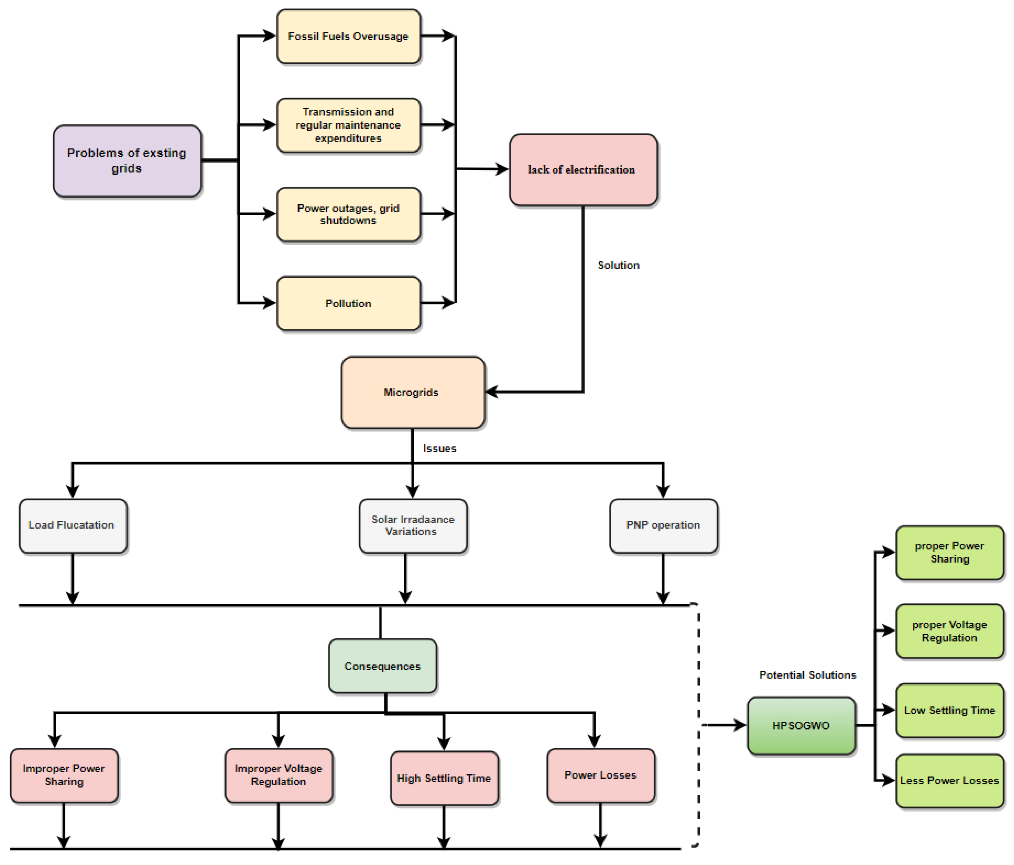
Figure 2.
DC MG configuration.
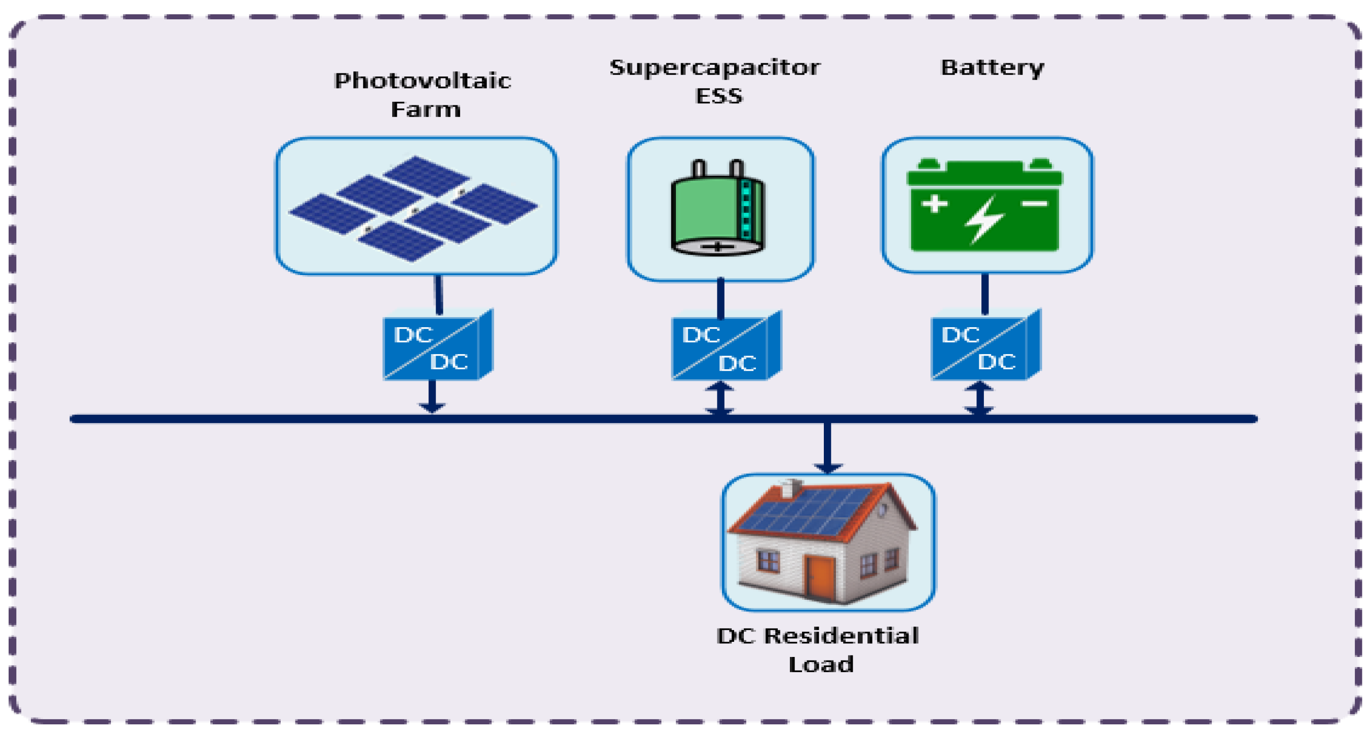
Figure 3.
Proposed control method.
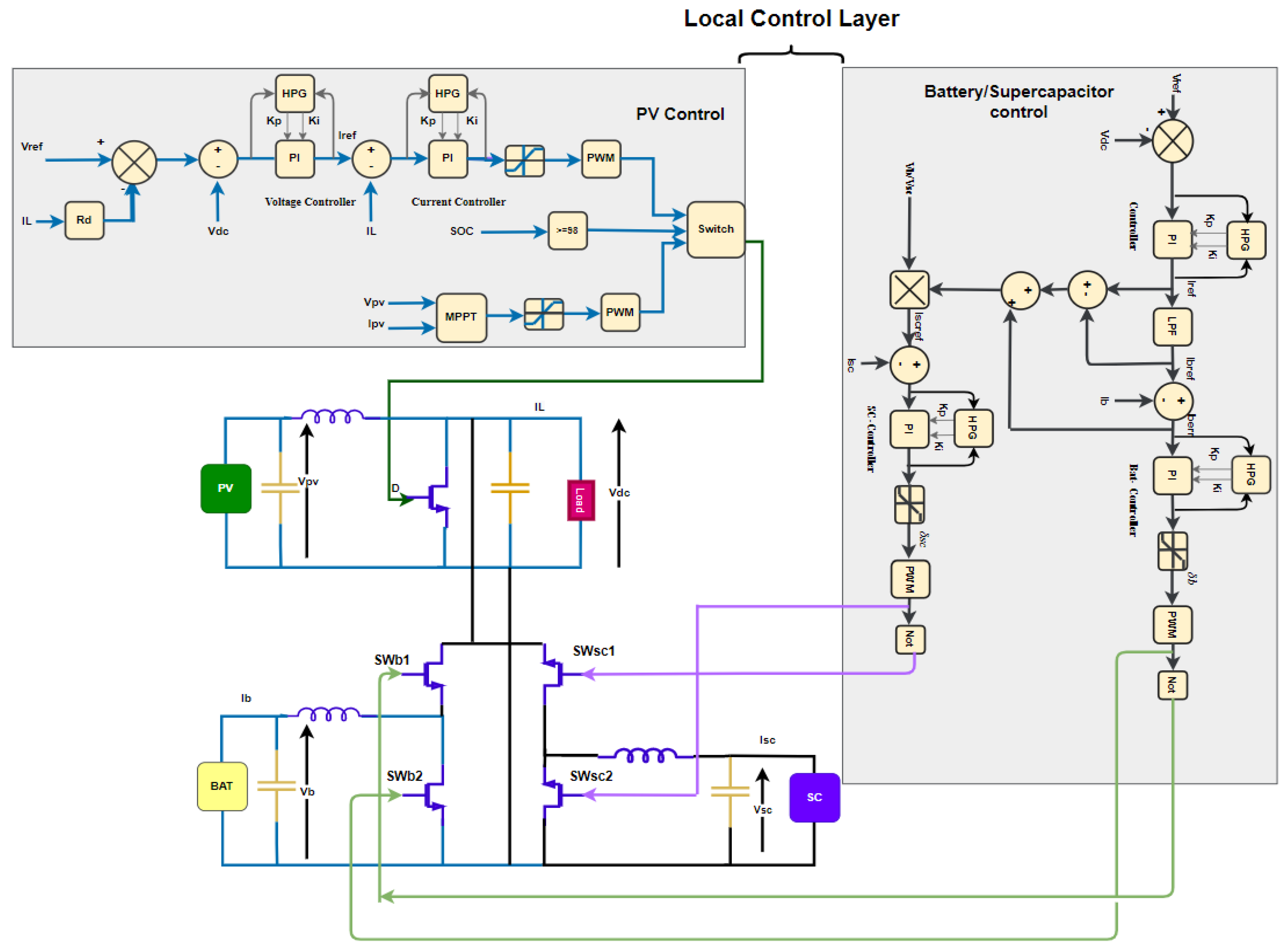
Figure 4.
HPSO–GWO flowchart.
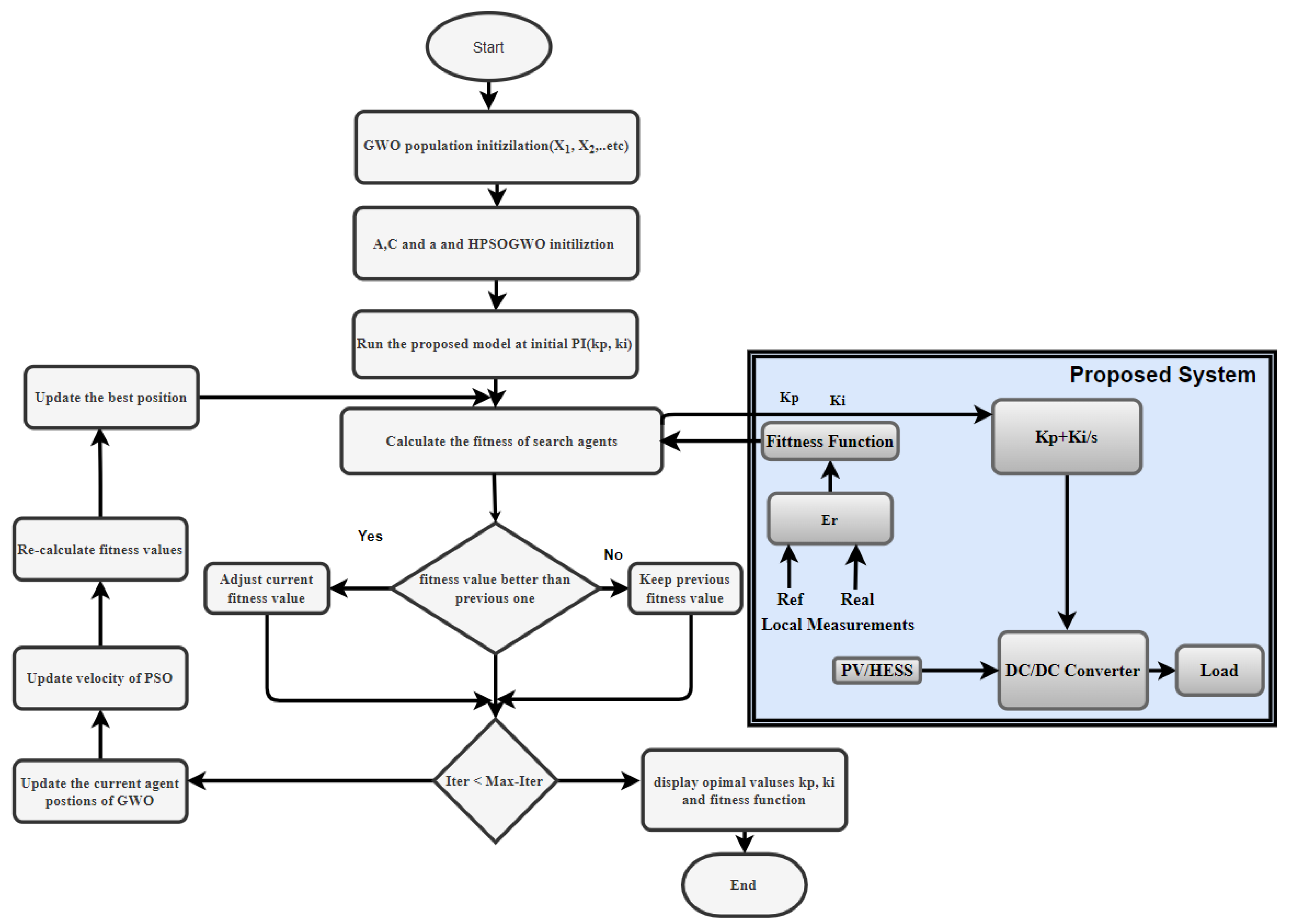
Figure 5.
Results with the conventional PI method: (a) DC-link voltage; (b) power exchange; (c) battery current; (d) SOC of battery; (e) SOC of supercapacitor.
Figure 5.
Results with the conventional PI method: (a) DC-link voltage; (b) power exchange; (c) battery current; (d) SOC of battery; (e) SOC of supercapacitor.
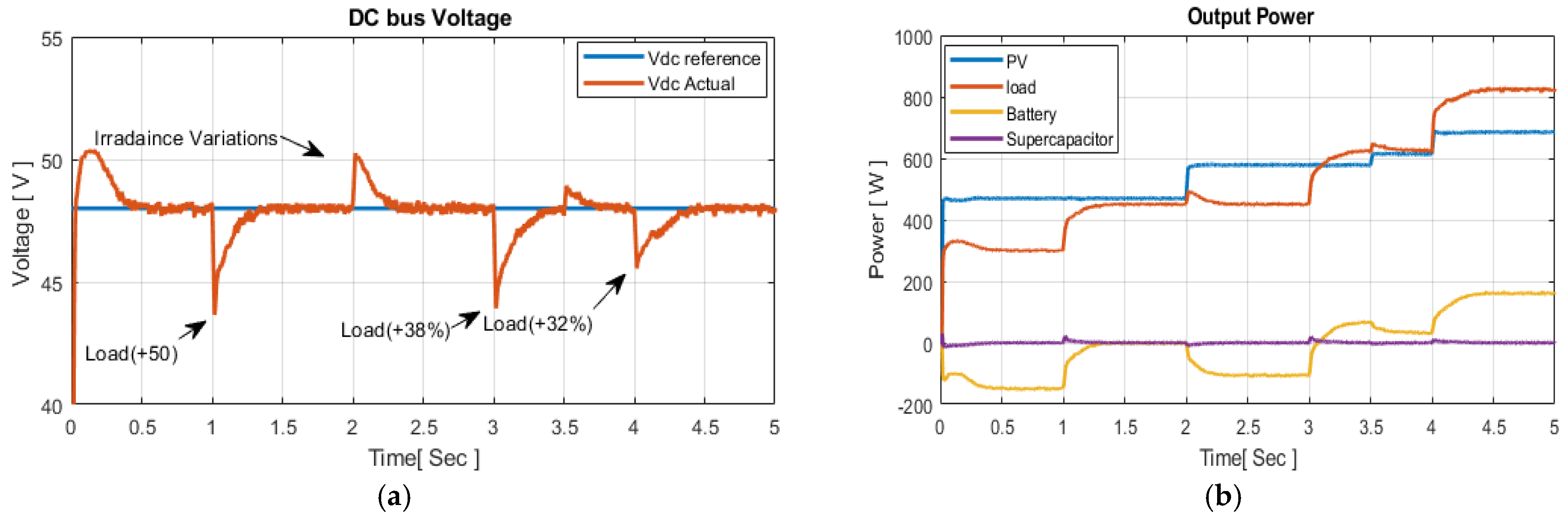
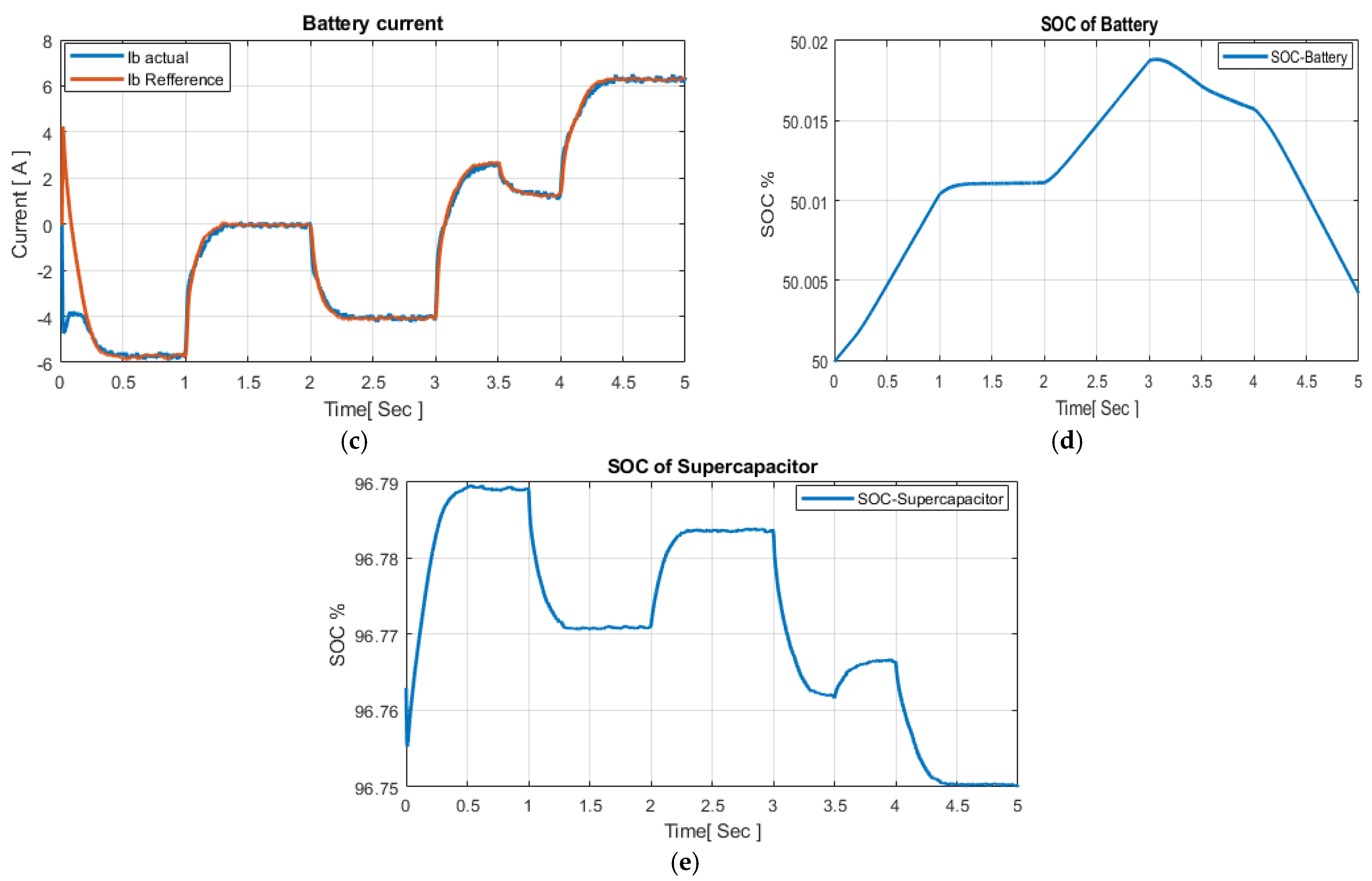
Figure 6.
Results with the GWO: (a) DC-link voltage; (b) power exchange; (c) battery current; (d) SOC of battery; (e) SOC of supercapacitor.
Figure 6.
Results with the GWO: (a) DC-link voltage; (b) power exchange; (c) battery current; (d) SOC of battery; (e) SOC of supercapacitor.

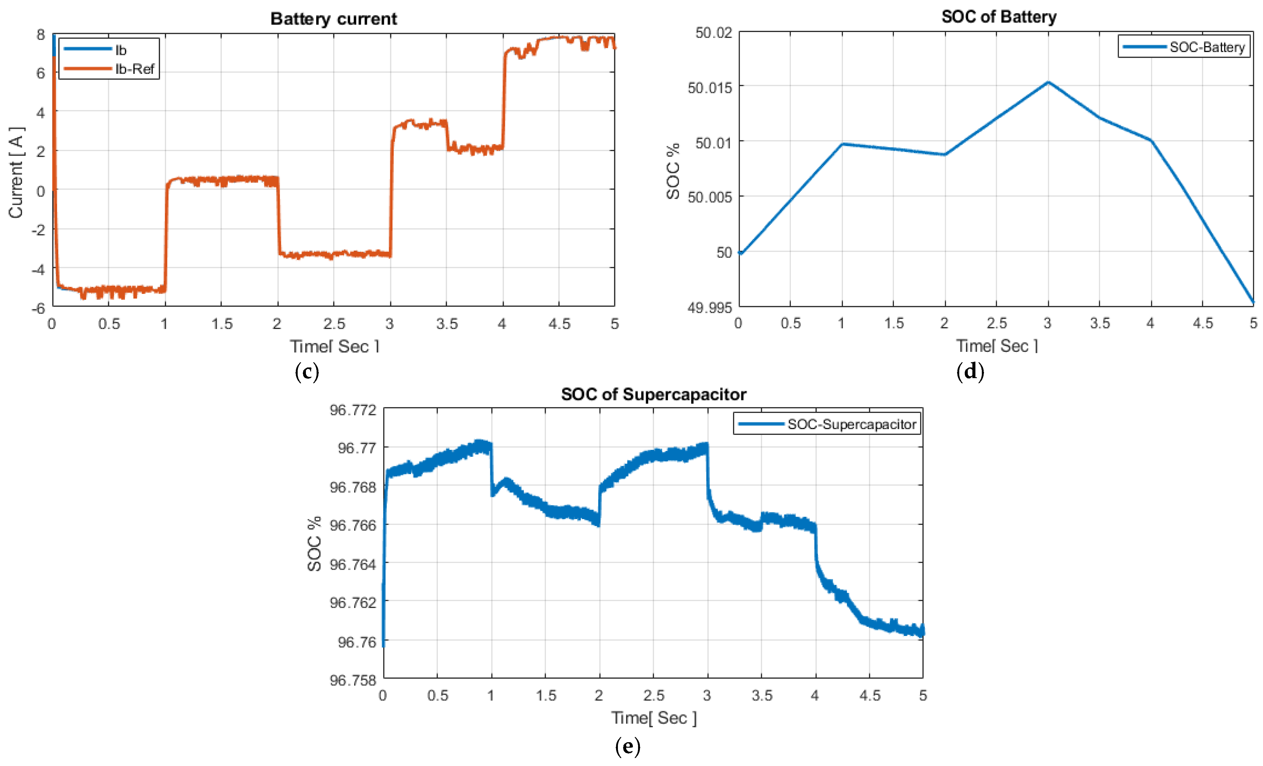
Figure 7.
Results with the hybrid PSO–GWO: (a) DC-link voltage; (b) power exchange; (c) battery current; (d) SOC of battery; (e) SOC of supercapacitor.
Figure 7.
Results with the hybrid PSO–GWO: (a) DC-link voltage; (b) power exchange; (c) battery current; (d) SOC of battery; (e) SOC of supercapacitor.
Figure 8.
Summary of the main results of the proposed control technique.


Table 1.
Optimal values of PI controllers.
| Controller | Kp | Ki |
|---|---|---|
| PI controller 1 | 10 | 200 |
| Battery controller | 50 | 166.4 |
| SC controller | 80 | 350 |
| Voltage controller (PV) | 4.2956 | 0.6284 |
| Current controller (PV) | 100 | 250 |
Publisher’s Note: MDPI stays neutral with regard to jurisdictional claims in published maps and institutional affiliations. |
© 2022 by the authors. Licensee MDPI, Basel, Switzerland. This article is an open access article distributed under the terms and conditions of the Creative Commons Attribution (CC BY) license (https://creativecommons.org/licenses/by/4.0/).
Share and Cite
MDPI and ACS Style
Al-Tameemi, Z.H.A.; Lie, T.T.; Foo, G.; Blaabjerg, F. Optimal Coordinated Control of DC Microgrid Based on Hybrid PSO–GWO Algorithm. Electricity 2022, 3, 346-364. https://doi.org/10.3390/electricity3030019
AMA Style
Al-Tameemi ZHA, Lie TT, Foo G, Blaabjerg F. Optimal Coordinated Control of DC Microgrid Based on Hybrid PSO–GWO Algorithm. Electricity. 2022; 3(3):346-364. https://doi.org/10.3390/electricity3030019
Chicago/Turabian StyleAl-Tameemi, Zaid Hamid Abdulabbas, Tek Tjing Lie, Gilbert Foo, and Frede Blaabjerg. 2022. "Optimal Coordinated Control of DC Microgrid Based on Hybrid PSO–GWO Algorithm" Electricity 3, no. 3: 346-364. https://doi.org/10.3390/electricity3030019