
Electrospinning: Processes, Structures, and Materials

Department of Chemical Engineering, Laval University, 1065 Avenue de la Médecine, Quebec City, QC G1V 0A6, Canada
*
Author to whom correspondence should be addressed.
Macromol 2024, 4(1), 58-103; https://doi.org/10.3390/macromol4010004
Submission received: 30 November 2023
/
Revised: 30 January 2024
/
Accepted: 6 February 2024
/
Published: 11 February 2024
Abstract
:Electrospinning is a simple and affordable method of producing nanofibers, offering a large specific surface area and highly porous structures with diameters ranging from nanometers to micrometers. This process relies on an electrostatic field, providing precise control over the fiber dimensions and morphologies through parameter optimization and the use of specialized spinnerets and collectors. The paper extensively covers the electrospinning process and parameters, shedding light on the factors influencing electrospinning. It addresses the morphological and structural aspects of electrospun fibers that are used in different applications. Additionally, this paper explores various polymeric and non-polymeric materials used in electrospinning. Furthermore, it investigates the incorporation of fillers during electrospinning, using an electric field to enhance properties and functionality. The review concludes by offering insights into upscaling electrospinning production.
1. Introduction
Nanofibers have received considerable focus and interest from scientific researchers and industry professionals due to their exceptional properties and wide-ranging applications. These nanofibers offer distinct advantages over conventional fibrous structures, such as a high surface area-to-volume ratio, tunable porosity, superior mechanical strength, and a broad range of material options. These qualities make nanofibers highly suitable for diverse applications, including filtration and separation, electronics and sensors, tissue engineering, and energy storage [1,2]. Among the different methods of producing nanofibers, electrospinning stands out as one of the most practical approaches due to its simple equipment requirements, cost-effectiveness, and the ability to produce continuous nanofibers with outstanding features such as diameters down to the nanometer range, large specific surface area, and high porosity [2,3]. The earliest efforts to apply electrospun nanofibers for practical purposes date back to the late 1930s in the Soviet Union, when Petryanov and his colleagues used fibrous cloth (Petryanov filters) to protect against radioactive aerosols [4]. This pioneering work led to the establishment of a factory for manufacturing gas masks with nanofiber-based mats, achieving a production capacity of 6.5 kg/h in the 1950s–1960s. Subsequently, in the 1980s, the United States saw the commercialization of its first sub-micrometer electrospun nanofiber product for air filtration by Donaldson Co., Inc. [5]. The 1989 development of microdenier fibers by DuPont marked another milestone in the field [5]. In the 1990s, electrospinning received renewed attention when Reneker and his colleagues demonstrated electrospinning’s capability to produce nanoscale materials and the significant value of the resulting organic nanomaterials [6,7]. This period marked a turning point in electrospinning’s history, as it gained recognition for its potential in various applications. Throughout the 21st century, electrospinning has garnered significant attention. A diverse array of materials and solvents have been combined to tailor the properties and functions of electrospun products, which have been studied in various fields, including filtration, tissue engineering, drug delivery, and more [3].
Several insightful reviews have been previously published on electrospinning and its diverse applications [3,8,9,10,11,12]. This comprehensive review expands upon the existing literature by offering a complete overview of the effects of different parameters on the morphology of electrospun fibers. It also explains the fabrication methods for fibers with different structures and sheds some light on the diverse array of materials used in electrospinning, including various polymers and fillers, and carefully considers the upscaling methods involved. By covering these different subjects, this contribution aims to provide a precise and in-depth reference for the complex interactions related to the field of electrospinning.
This paper begins by explaining the basic principles of the solution electrospinning process. It then describes the parameters that influence electrospinning. Subsequently, it explores the various morphologies and structures of electrospun fibers. The paper discusses the diverse types of nanofibers that can be produced through electrospinning. It also describes the different nanofillers used in electrospinning. Finally, it addresses the upscaling production of electrospun fibers.
2. Principles of Solution Electrospinning
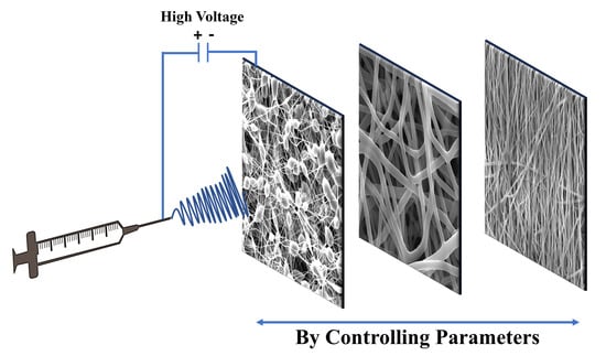
Electrospinning is a unique technique that relies on the application of an electrostatic field to generate ultrafine fibers [13]. Generally, this process uses a straightforward setup consisting of four main components, as shown in Figure 1: a high-voltage power supply, a syringe pump, a spinneret (a syringe with a blunt-tip needle), and a fiber collector. In this process, a polymer is dissolved in a highly volatile solvent which is ejected from a syringe at a constant/controllable rate via the syringe pump. Due to the electrostatic force applied, a separation of positive and negative charges occurs within the liquid and charges of the same sign as the needle’s polarity move toward the surface, resulting in the formation of a charged polymer droplet at the needle’s tip [3,14]. By increasing the intensity of the electrostatic field, the surface charges density on the droplet rises, leading to enhanced mutual charge repulsion on the liquid’s surface. This, in turn, causes an expansion of the droplet’s surface area, mitigating repulsion. Consequently, the drop shape changes to a Taylor cone. Ultimately, the electrostatic repulsion overcomes surface tension, and a jet emerges, which is rapidly moving toward the collector. As the jet progresses towards the collector, the polymer solution elongates and undergoes a whipping phenomenon, while the solvent undergoes evaporation. These processes collectively result in the formation of very small fibers.
Typically, the electrospinning procedure can be divided into four successive steps: the formation of a Taylor cone at the needle’s tip, the ejection of the charged jet in a straight line, the stretching of the jet into finer diameters and the growth of physical instability, and finally, fiber solidification and deposition on the collector [16,17].
A well-formed Taylor cone is crucial for establishing a stable electrospinning process which controls the diameter and morphology of nanofibers [18,19]. Irregular or unstable Taylor cones can lead to non-uniform nanofibers or even the formation of beads. Furthermore, Zhao et al. [20] have both theoretically determined and experimentally verified a direct relationship between the height of the Taylor cone and the diameter of the resulting nanofibers. This relationship can be valuable in optimizing the electrospinning process and improving the quality of the produced nanofibers.
The jet emerging from the Taylor cone initially moves in a nearly straight line. This specific segment, often of short length, is designated as the near-field region [3] (Figure 2c). The velocity, length and diameter of the jet within the straight segment was studied by several research groups [21,22]. Zheng and colleagues [23] conducted a study examining the effect of the jet’s path on polystyrene (PS) fibers. Their research revealed that an increase in the length of the straight segment resulted in an increase in fiber diameters.
While the jet accelerates in a straight line, its diameter continuously decreases. However, even a small perturbation at this stage can disrupt the straight trajectory, leading to instability. This instability can easily arise due to electrostatic repulsion among the surface charges on the jet as it enters the far-field regime [3]. This electrically charged jet can undergo three types of physical instabilities, as shown in Figure 2a,b, which affect the size and geometry of the electrospun fibers [3,13]. The first is the axisymmetric Rayleigh instability (jet centerline). The second is also an axisymmetric instability and the third, which is known as a whipping instability, is non-axisymmetric. The Rayleigh instability leads to jet breakup and the formation of a beaded fiber. The high surface tension and low viscosity of the solution contribute to the occurrence of this instability, which can be suppressed by a higher electric field or by increasing the polymer concentration in the solution. Electrospinning of a 4 wt.% poly(3-hydroxybutyrate-co-3-hydroxyvalerate) PHBV solution at 10 kV produced fibers with beads initially featuring a 1.5 µm fiber diameter with an average bead size of 14 µm. However, increasing the voltage to 30 kV while keeping the other parameters constant resulted in fibers with uniform diameters of 1.5 µm [24]. The second type of instability happens in a stronger electric field than the first type due to electrostatic repulsion between the jet surface charges leading to the generation of a series of loops and a coil with numerous turns around the original direction. This effect causes the thinning and elongation of the jet.
However, in the electrospinning process, non-axisymmetric whipping instability plays a central role in reducing the jet diameter from micrometer to nanometer. The whipping instability was extensively explored and comprehensively explained by Reneker et al. [7]. For strong electric fields, the charge density in the jet is enhanced so the axisymmetric instabilities become repressed and non-axisymmetric instability increases. As a result, the length of the jet increases with a large elongation rate (up to 106 s−1), and ultimately, the jet experiences a large reduction in diameter [3]. The solidification of the jet into fibers occurs through solvent evaporation [3]. The rate of solidification plays an important role in determining the characteristics of the resulting fibers. Slower solidification leads to longer elongation, producing thinner fibers. Once solidified, the fibers retain their charges but become stable. They subsequently accumulate on a grounded collector, forming various morphologies based on the state of instability. Some residual charges remain on the fibers’ surface after deposition, often limiting the mat thickness to around 0.5–1 mm due to charge repulsion [25].
Figure 2.
(a) Schematic representation showing the trajectory of an electrospinning jet [26]. Reproduced with permission from Renker, and Yarin, Polymer; published by Elsevier, 2008. (b) snapshot of an electrospinning jet; (c) straight part of an electrified jet [27]. Reproduced with permission from Han et al., Polymer; published by Elsevier, 2007.

3. Parameters Related to Solution Electrospinning
Optimization of the electrospinning conditions attracted the interest of a large group of researchers. Their studies focused on several variables used to obtain nanofibers with specific morphology and desirable properties in a reproducible way. Generally, these variables can be classified into the following three categories [14,17]:
- Solution parameters: polymer molecular weight (Mw), polymer concentration (C), solution conductivity (k), solution surface tension (γ), and type of solvent.
- Process parameters: flow rate (Q), applied voltage (V), distance between the needle and collector (d), needle diameter (D), and type of collector (fixed or mobile).
- Ambient parameters: temperature, relative humidity, and air velocity.
- The main effects of these parameters on the fiber morphology are discussed in Table 1, while a comprehensive explanation of each parameter is provided in the following section.
3.1. Solution Parameters
3.1.1. Concentration, Viscosity, and Molecular Weight
Generally, solution viscosity (η), polymer molecular weight (Mw), and polymer concentration (C) are interrelated parameters. These parameters are known to affect the solution electrospinnability and consequently the final morphology (diameter, roughness, porosity, etc.) of the nanofibers. Unfortunately, they cannot be investigated separately [34,45]. Solution concentration is one of the key factors for optimizing the morphology of the nanofibers [40]. The solution concentration determines the spinnability of polymer solution due to its effect on the viscosity/elasticity (rheology) and surface tension. When the solution is too dilute, individual drops are formed (electrospray) instead of continuous fibers due to high surface tension and low viscosity. With a slight increase in concentration, the nanofibers become unstable, resulting in a mixture of beads and fibers. At the optimum concentration, bead-free nanofibers are produced, as shown in Figure 3. Polymer solutions with high concentration are unsuitable for electrospinning due to their elevated viscosity [19,46]. Furthermore, it has been shown that increasing the solution concentration leads to larger fiber diameter. For instance, Bosworth et al. [28] conducted a study investigating the effect of polycaprolactone (PCL) concentration in acetone and found that higher concentrations (10% w/v) resulted in the production of bead-free fibers with a wide range of diameters. Gu and Ren [29] reported similar findings for poly(D,L-lactide) (PDLA) in a solvent mixture of chloroform and acetone (2/1 v/v). Bead-on-string structures were generated at lower concentration (3 wt.%), while continuous and uniform nanofibers were obtained at higher concentration (7 wt.%) and the average fiber diameter increased with the polymer solution concentration. It is worth noting that the solution viscosity can be controlled by adjusting the polymer concentration [14]. The effect of viscosity on electrospun nanofibers aligns with that of concentration: as the viscosity increases, the shape of the beads changes from spherical to spindle-like until it ultimately results in the formation of smooth fibers, but with increased diameter. For instance, Cooper et al. [47] conducted a study involving film-grade biobased poly(butylene succinate) PBS solutions at three distinct concentrations (5%, 10%, and 15% w/v) in chloroform/dimethyl sulfoxide (DMSO) solvent systems. Their findings revealed distinct outcomes based on solution concentration. In the first solution (5%), the viscosity was notably lower compared to the other two solutions, resulting in the formation of spherical droplets characterized by a roundness value of 0.70 ± 0.17. Moving to the second solution (10%), the increased viscosity allowed for the generation of fibrous structures. However, the Rayleigh instability remained prominent, giving rise to spindle-like fibers with a roundness value of 0.55 ± 0.15. The third solution (15%) exhibited higher viscosity, effectively suppressing the Rayleigh instability in favor of other bending instabilities and ultimately producing defect-free fibers. Moreover, molecular weight, alongside concentration and viscosity, is a predominant factor influencing the morphology and diameter of electrospun fibers [48]. Zaarour et al. [30] conducted a study illustrating that molecular weight significantly affected the surface structure and mechanical properties of wrinkled electrospun polyvinylidene fluoride (PVDF) fibers. Increasing the molecular weight resulted in an enhanced degree of surface wrinkling and a larger diameter with a higher tensile strength and Young’s modulus.
In terms of molecular weight effects, maintaining a constant concentration while decreasing the molecular weight results in the formation of beads. Conversely, increasing the molecular weight leads to the generation of smooth fibers [33]. Mwiiri et al. [32] studied the effect of molecular weight and concentration on the electrospinning of poly(vinyl alcohol) (PVA). The molecular weight of PVA ranged from 67,000 to 186,000 g/mol, and the concentration (C) of the polymer in the solution varied from 5 to 20 wt.%. The fiber diameter was found to increase with both molecular weight and concentration. However, a further increase in molecular weight resulted in the formation of flat and non-uniform thicker fibers.
Polymer chain entanglement is another crucial factor determined by molecular weight. It prevents the electrospun jet from breaking and results in the formation of a continuous polymer jet rather than droplets or beads [50]. To quantify the effect of entanglements on the electrospun fiber formation, the following relation is used [45]:
where C* is the critical chain overlap concentration and [η] represents the intrinsic viscosity. Based on this analysis, four concentration regimes for polymers dissolved in a good solvent were identified: dilute (C/C* < 1), semi-dilute unentangled (1 < C/C* < 3), semi-dilute entangled (C/C* > 3), and concentrated. The transition between the semi-dilute unentangled and semi-dilute entangled concentration regimes is observed at C/C* ~ 3, which is a sufficient level of entanglements needed to produce nanofibers and can be defined as the entanglement concentration (Ce) [45]. In the dilute concentration regime, due to the separation of polymer chains and insufficient chain overlap, only polymer droplets are generated. In the semi-dilute unentangled regime, as the concentration increases, droplets and beaded fibers are collected. In the semi-dilute entangled regime, when the concentration is higher than Ce, beaded as well as uniform fibers are produced. The number of beaded fibers decreases as the polymer concentration increases, ultimately leading to the production of uniform fibers. This phenomenon occurs when the concentration is 2–2.5 times Ce [51].
3.1.2. Surface Tension
Surface tension, which is affected by the type of solvent and molecular interaction within the polymer solution, plays a key role in controlling the morphology of electrospun fibers. Therefore, a careful selection of the solvent is important not only to achieve a homogeneous polymer solution, but also to obtain an appropriate surface tension [52]. To start the electrospinning process, the electrostatic force must overcome surface tension. Surface tension tends to decrease the surface area by forming a sphere-like shape, while the electrostatic force tends to increase the surface area through elongation [26]. Basically, if all the other variables are fixed, surface tension establishes the upper and lower boundaries of the electrospinning window [53]. High surface tension inhibits the process of electrospinning, leading to instability with an increased tendency for the jet to break, resulting in beaded fibers. Conversely, studies have shown that reducing the surface tension of the polymer solution allows for the production of nanofibers without beads, resulting in a more uniform fiber structure [34,53]. But different methods were proposed to adjust the surface tension of polymer solutions. For instance, by using solvents with lower surface tension, an adequate surface tension can be achieved for electrospinning. Yang and colleagues explored the effect of ethanol, N,N-dimethylformamide (DMF) and methylene chloride (MC) on the morphologies of electrospun polyvinyl pyrrolidone (PVP) fibers [54]. The study revealed that by reducing the surface tension of the solution while maintaining constant concentrations, they could reduce the occurrence of bead formation and achieve a uniform production of nanofibers. Adding a surfactant to the solution is another way to reduce the surface tension and generate more uniform fibers [26]. However, the effect of surface tension on the fiber diameter has been reported in two opposite manners. The addition of a surfactant can either promote an increase in surface area, thus limiting bead formation and promoting the formation of finer jets, or it may result in an increase in fiber diameter. This increase can be attributed to higher viscosity, hindering the stretching process, ultimately leading to the production of thicker fibers. Castkova et al. [55] observed that the diameter of poly(vinylidene fluoride) (PVDF) fibers was significantly affected by the addition of cetyltrimethylammonium bromide (CTAB), resulting in a decrease from 649 to 276 nm. Deng et al. [56] investigated the effect of three types of surfactants, non-ionic (Tween 80), anionic (sodium dodecyl sulfate, SDS), and cationic (cetyltrimethylammonium bromide, CTAB), on the morphology of gelatin nanofibers. They observed that adding 1% SDS, CTAB or Tween 80 resulted in a sudden drop in surface tension from 37.86 mN/m to 31.08 mN/m, 19.24 mN/m, and 19.76 mN/m, respectively. Furthermore, their findings revealed that all three surfactants produced smooth fibers. However, SDS significantly increased the fiber diameter.
3.1.3. Conductivity
Conductivity represents the charge density and repulsion of the charges at the surface of the electrospinning jet and is responsible for the amount of elongation and stretching of a jet due to the enhanced whipping instability [14,34]. Several studies have shown that in general, fibers with smaller diameters and less beading can be produced by increasing the electrical conductivity of the solution [36,37,47]. It should be mentioned that when a solution without significant conductivity is used, fiber formation becomes impossible because the charges cannot be conducted from the interior of the solution to its surface [3]. However, if the solution is highly conductive, the radius of curvature of the Taylor cone becomes very small, making the initiation of bending instability more challenging; thus, increasing the electrical conductivity in a proper range will lead to the formation of thinner fibers [3,57].
The addition of salts is another strategy to decrease bead formation and improve the production of thinner nanofibers [36,37]. For instance, Klairutsamee et al. [58] incorporated an organic salt (alkyl ammonium ethyl sulfate, AAES) into a solution of 12% w/v polybutylene succinate (PBS) in chloroform (CF) for a concentration ranging from 0.25 to 1% w/v. It was observed that the addition of salt resulted in a substantial increase in the solution conductivity and a significant drop in the fibers’ diameter. Similarly, Topuz et al. [59] reported that tetraethylammonium bromide (TEAB) salt highly enhanced the conductivity of polyimide (PI) solutions, substantially improving spinnability and leading to thinner fibers. Conversely, it is worth mentioning that the addition of salt to electrospinning solutions can also result in the generation of nanofibers with a larger diameter. Nartetamrongsutt and Chase [60] found that as the concentrations of LiCl and MgCl2 increased, a notable rise in the average diameter of polyvinyl pyrrolidone (PVP) fibers was observed. However, NaCl did not exhibit a similar effect. Mit-Uppatham et al. [61] also reported that increasing the salt (NaCl and LiCl) content in polyamide (PA) solutions led to higher solution conductivity, solution viscosity, and fiber diameter. They explained that the formation of larger fibers is the result of increased viscoelastic force (mainly viscosity), which contracts Coulombic stretching force and prevents the stretching of the charged jet by the electrostatic forces. Furthermore, the ion size of the solution has a significant influence on the diameter of nanofibers [62]. Ions with smaller atomic radius, due to their higher charge density and higher mobility under an external electric field, produce uniform nanofibers with a narrow distribution of fiber diameter.
Another strategy for increasing conductivity is the addition of surfactant. Zheng et al. [63] examined the effect of various types of surfactants, including anionic sodium dodecyl sulfate (SDS), cationic hexadecyl trimethyl ammonium bromide (CTAB), and non-ionic (Triton X-100) surfactant, on the diameter and morphology of polyvinylidene fluoride (PVDF) nanofibers. The presence of surfactants increased the net charge density and instability of the charged jet, leading to the stretching of jets into finer fibers. The conductivity of the polymer solution increased with higher concentrations of SDS and HTAB. However, the addition of Triton X-100 did not affect the conductivity due to its non-ionic structure, which could not increase the free charge in the polymer solution. In addition, the use of an anionic surfactant (SDS) resulted in nanofibers with the smallest diameter, while the cationic surfactant (CTAB) improved bead formation and contributed to the production of uniform nanofibers.
It was also reported that the addition of conductive fillers/particles, such as carbon nanotubes (CNT), can change the charge density of a solution, resulting in finer fibers when using a CNT-containing solution compared to a solution without CNT [64].
3.1.4. Type of Solvent
The selection of an appropriate solvent plays an important role in the fabrication of smooth and bead-free electrospun nanofibers [65]. Two key factors are involved: the polymer’s solubility in the solvent and the solvent’s boiling point, which are vital for easy processing. The boiling point is related to the solvent’s volatility. Volatile solvents are preferable as they facilitate the nanofibers’ formation via evaporation during their trajectory from the capillary tip to the collector surface. However, highly volatile solvents are generally avoided due to their low boiling points and rapid evaporation rates, which can lead to the drying of the jet at the needle tip. This drying effect may cause a blockage at the needle tip, consequently hindering the electrospinning process. On the other hand, solvents with high boiling points may not completely evaporate before reaching the collector, leading to the formation of beaded nanofibers and fibers’ coalescence [65,66].
Other important parameters are the dipole moment and conductivity of the solvent, which can affect the electrospinnability of polymer solutions and the morphology of fibers. Jarusuwannapoom et al. [67] investigated the effect of 18 solvents on the spinnability of polystyrene (PS) solutions. The results revealed that only five solvents (DMF, THF, ethyl acetate, methyl ethyl ketone, and 1,2-dichloroethane) were suitable for electrospinning. This selection was based on the solvents’ superior conductivity and dipole moment.
3.2. Process Parameters
3.2.1. Voltage
The applied voltage is one of the crucial parameters in the electrospinning process due to its effect on the shape of the initial droplets, the formation of the Taylor cone, and the ejection of the polymer solution. Electrospinning occurs when a voltage higher than the critical voltage is applied, inducing the necessary charges on the droplets’ surface to overcome the surface tension of the solution; thus, an electrically charged jet is ejected [14,50]. There is still controversy in the literature about the effect of increasing the voltage on the diameter of electrospun fibers. Several studies have shown that increasing the applied voltage leads to fibers with smaller diameters due to continuous stretching caused by the electrical force [68,69,70]. For example, the morphological observations of Chowdhury and Stylios [38] clearly showed that thinner Nylon 6 fibers were collected by increasing voltage. A similar result was reported by Megelski et al. for polystyrene (PS) nanofibers [39]. On the other hand, some authors observed that the fiber diameter increased, and its distribution became broader with increasing voltage [71,72]. This was explained by the ejection of more solution and the shorter flight time of the jets [17]. Liu et al. [73], via numerical simulation and experimental verification, found that under high voltage, the number of jets emitted from the needle tip increases. Subsequently, the entire electrospinning process and the resulting nanofiber morphology were highly affected by the jet evolution mechanism. They attributed this observation to the fact that as voltage increased, a more concentrated electrical field at the needle tip led to a gradual disappearance of protruding droplets, ultimately resulting in the emission of multiple jets afterwards (Figure 4). Therefore, the electrospinning process can be divided into two stages: before and after the disappearance of the protruding droplet. In the first stage, as the voltage is increased, the fiber diameter decreases, leading to a relatively uniform diameter distribution. However, in the second stage, the fiber diameter increases due to a higher number of jets causing the electrical field to be distributed among these multiple jets. Each jet faces a weakened electrical field, which contributes to the formation of thicker nanofibers and a broader fiber distribution. This occurs because the spinning process becomes unstable due to different electrical field intensity being imposed on each jet and a variable number of jets. As a consequence, the appropriate voltage for fabricating nanofibers with a small diameter and narrow fiber diameter distribution is the critical value before the protruding droplets disappear.
3.2.2. Distance between the Needle and Collector
The distance between the collector and the needle tip has been considered as another approach to controlling fiber diameter and morphology due to the effect of distance on the jet path, traveling time, and solvent evaporation [14]. In general, increasing the distance leads to the formation of thinner fibers due to higher stretching forces (when the distance is too short, jet stretching is limited), resulting in large diameter and beaded fibers [28,38,40]. If the distance is too far, beaded structures are formed due to the weak electric field strength generated [38]. Therefore, an optimum distance is required to produce bead-free fibers. This occurs when the electric field strength is sufficient to overcome the surface tension force and the residence time is long enough for sufficient solvent evaporation [74]. However, there are some exceptions. For instance, some authors reported that the fiber size does not significantly change when varying the distance, but bead formation may occur when the distance is too short [39,75]. Lee et al. [76] showed that the diameter of poly(vinyl alcohol) (PVA) nano-fibers increased with a longer distance because of less stretching on the resultant fibers as a consequence of reduced electrostatic force.
3.2.3. Flow Rate
The morphology and diameter of electrospun nanofibers are highly influenced by the solution flow rate. In fact, the flow rate affects the jet velocity and stability of the Taylor cone, making it essential to find the optimal value. Generally, reducing the polymer solution flow rate results in smaller nanofiber diameters and the formation of uniform fibers because it allows sufficient time for solvent evaporation [41]. However, when the flow rate falls below a certain threshold, the solution at the needle tip is removed at a faster rate than the flow rate generated by the electric forces, leading to an unstable jet, thereby resulting in beaded nanofibers or even needle blockage [70]. Conversely, increasing the flow rate leads to larger fiber diameters. However, an excessively high flow rate results in the formation of beaded fibers due to the instability of the Taylor cone and improper evaporation/solidification time [41,70].
3.2.4. Collector
During the electrospinning process, nanofibers are usually deposited on a conductive collector. The type of collector has a significant effect on the productivity, nanofiber alignment, and structure of the collected mat. In terms of productivity, a conductive collector influences the reduction of the charges on the deposited fibers, therefore reducing the repulsive forces between the fibers [77]. This results in a higher number of fibers being collected. For a less conductive collector, the number of fibers deposited is reduced, and beaded fibers may be generated. To promote the deposition of fibers on a collector when dealing with materials of low conductivity, it can be beneficial to decrease the charge density of the electrospinning jet by minimizing the accumulation of residual charges [77]. One approach to collecting fibers onto a nonconducting surface involves the use of AC high-voltage electrospinning as an alternative to the conventional DC high-voltage method [78]. Moreover, a study focusing on the effect of various support materials (polypropylene, polyethylene, polyethylene terephthalate, aluminum, acetate fiber and paper) and grounding electrodes (a drum, wire, or a support material positioned 40 mm away from the wire electrode) in collecting polyvinyl alcohol fibers revealed that the choice of grounding electrode had a more significant effect on the amount of collected fibers compared to the type of support material [79]. The electrospinning process typically leads to the formation of a layer of nanofibers on a collector, often forming a nonwoven network on a smooth surface. The intentional control of fiber structures has important implications for the performance of these fiber assemblies. Consequently, substantial efforts have been directed toward modifying collectors to broaden the scope of application for electrospun fibers by controlling the fiber alignment and orientation as well as the mats’ structures [3]. More detailed information on this topic can be found in the section dedicated to aligned structures (Section 4.1).
3.3. Ambient Conditions
Ambient conditions such as temperature and humidity can influence the diameter and morphology of electrospun nanofibers [80]. The effect of temperature on the average fiber diameter can be explained by two opposing effects: (a) an increase in the solvent evaporation rate, and (b) a decrease in the viscosity/surface tension of the polymer solution. Vrieze et al. [42] reported that smaller PVP nanofibers were produced at both the lowest (283 K) and highest (303 K) temperatures. At the lowest temperature, the dominant factor was the rate of solvent evaporation, which decreased with lower temperature, resulting in higher jet elongation. However, at the highest temperature, the viscosity became the dominant factor. In fact, increasing the temperature enhanced the polymer chain’s mobility, leading to a viscosity drop. Consequently, the stretching rate increased, resulting in thinner fibers. For the humidity, the effect of this parameter depends on the hydrophilicity/hydrophobicity of the polymer and the solvent properties [43]. Icoglu et al. [44] showed that electrospinning at higher humidity led to the formation of large-diameter polyethylenimine (PEI) fibers. This was attributed to the rapid precipitation of PEI in the polymer solution jet by absorption of water, resulting in lower jet elongation. On the other hand, Pelipenko et al. [81] reported that the diameter of PVA nanofibers decreased when the humidity increased from 4% to 70%. Beaded fibers were also produced at the highest humidity (70%). Furthermore, low humidity resulted in larger nanofibers with a more homogeneous size distribution, while high humidity led to smaller nanofibers with a more homogeneous size distribution. Variation in humidity could be explained by the rate of solvent evaporation as it is reduced at high humidity and the polymer jet solidifies more slowly, resulting in the formation of thinner nanofibers. Additionally, the mechanical properties of the fibers were affected by humidity: smaller nanofibers were achieved at higher humidity and exhibited a stiffer structure. Nezarati et al. [82] performed the electrospinning of three different polymers: poly(ethylene glycol) (PEG), poly(caprolactone) (PCL), and poly(carbonate urethane) (PCU), which were dissolved in three different solvent systems: chloroform (CF), a mixture of CF/DMF (80/20 v/v), and dimethylacetamide (DMAc), respectively, to investigate the effect of humidity (5–75%). The authors observed distinct differences between the morphology of nanofibers from various polymer–solvent systems. At lower humidity (<50%), fiber breakage for all three polymers occurred because of the low electrostatic charge dissipation of the jet. At higher humidity (>50%), beaded and broken fibers of hydrophilic polymer (PEG) were observed due to improved water absorption and reduced solution concentration. On the contrary, electrospinning of hydrophobic polymer (PCL dissolved in CF) produced porous fibers. This was explained by a hydrophobic polymer, high-volatility solvent (CF), and a water-miscible solvent (DMF) that facilitated the vapor-induced phase separation (VIP) phenomena. For PCU, the most hydrophobic of the three polymers, raising the humidity (20–75%) resulted in smooth and uniform fibers due to the low volatility of DMAc (water-miscible solvent), but the fiber cross-section showed a porous core attributed to the polymer hydrophobicity. In addition, the density of PCU fibers decreased at higher humidity (50–75%) due to a drop in charge dissipation.
4. Structures/Morphologies
An appealing aspect of electrospinning is its ability to produce nano- to micro-fibers with diverse structural arrangements and morphologies, which are tailored to yield different properties for specific applications. Through careful optimization of the electrospinning parameters, as well as the selection of specialized spinnerets and collectors with unique configurations, researchers have successfully generated nanofibers with special morphologies such as aligned, core–shell, hollow, porous, etc. Typical examples are presented in Figure 5. Additionally, Table 2 provides a comprehensive list of fiber structures, along with the corresponding spinnerets and collectors used in their production. The table also reports on the applications associated with each configuration. In the subsequent sections, more exploration of the final morphology is presented.
4.1. Aligned Structure
Control over the alignment and orientation of nanofibers is of significant importance for creating anisotropic structures with improved complexity and performance for various fields [107]. In drug delivery, aligned fibers were shown to be beneficial in controlling release performance. Compared to randomly arranged fibers, aligned fibers showed a decrease in burst release with an increase in sustained and controlled drug release [93]. In tissue engineering for the regeneration of muscles [94], bones [92], and neural cells [95], several studies have reported that cell cultures on uniaxially aligned nanofibrous scaffolds were more favorable as they promoted cell adhesion, migration, and proliferation [92,94]. In sensor applications, Wu et al. [96] reported that well-aligned nanofibers were more efficient in producing piezoelectric sensors.
Based on the value of orienting electrospun nanofibers, several modifications were introduced to the electrospinning collector’s geometry. Due to the benefit and importance of the orientation of electrospun nanofibers, a great deal of effort was devoted to modifying the collector. These modifications are facilitated by taking advantage of mechanical, electrostatic, and magnetic forces [3].
A rotating collector takes advantage of high velocities and mechanical tensile force to induce fiber alignment [108]. In this method, a substrate that is moving at a high speed is used to control the deposition pattern of the high-velocity jet [108]. The rotational speed of the collector has an important effect on the fiber diameter and alignment as increasing the speed of rotation can lead to a smaller fiber diameter [109,110]. Effective fiber alignment is only achieved when the rotational velocity is above a critical threshold, at which point an increase in speed corresponds to improved alignment, but operating the collector at excessively high speeds can result in fiber breakup. This critical speed varies across different systems [111]. Courtney and colleagues [112] showed how the speed of rotation influenced the degree of alignment. Their findings indicated that a minimum velocity of 2 m/s was essential to initiate alignment, emphasizing the importance of this threshold in creating anisotropic structures. Additionally, as the rotational speed increased, the alignment degree improved. This enhanced fiber alignment was associated with improved mechanical properties in the preferred direction, including an increased modulus. Moreover, researchers improved fiber alignment by modifying the geometry of the rotating collector to suit their specific applications. This includes using options such as a rotating disc, rotating rod, or conical mandrel (Figure 6) [107]. Xue et al. [113] reported on the fabrication of aligned nanofibrous scaffolds with an average diameter of 500 nm mimicking the structure of the middle layer in a native artery. They achieved this structure using electrospinning with a rotating disk collector with a sharp edge. In another study, scaffolds produced using a conical mandrel showed anisotropic microstructures with changing fiber alignment angles, mimicking a heart valve [97]. This curvilinear alignment potentially homogenized the strain field and decreased the stress concentration compared to linearly aligned fibers. Finally, when using mechanical alignment, it is important to take into account variables such as the mat dimensions, desired level of alignment, and capacity to fine-tune alignment angles. Although rotating collectors offer some control over anisotropy, they may not be suitable for applications requiring extremely precise alignment.
The parallel collector represents an alternative method of producing highly aligned electrospun materials [111]. It is composed of two parallel electrodes separated either by an air gap or an insulating substrate. In contrast to the rotating collector method, which relies on mechanical force, the parallel collector uses electrical forces to induce fiber alignment.
Li et al. [114] conducted research on the preparation of aligned fibers using a collector composed of two electrically conductive substrates separated by a gap ranging from micrometers to several centimeters. The insulating gap distance was observed to have a significant effect on the degree of fiber orientation; a larger gap often resulted in superior fiber alignment [115]. However, a maximum gap size exists beyond which exceedingly thin nanofibers are prone to break due to their inability to withstand both their own weight and the repulsive charges from neighboring fibers [114].
Additionally, this technique is constrained by the achievable thickness of mats. As the thickness increases, residual charge accumulates, eventually leading to repulsion among fibers and a loss of fiber alignment. Consequently, as the mat thickness increases, the deposition of increasingly random fiber orientations becomes inevitable [3]. Several modifications have been made on parallel collectors to achieve the desired microstructure for specific applications such as the rotating wire drum and two-pole parallel collector (Figure 7). Xie et al. [98] reported on the fabrication of aligned-to-random scaffolds by using a parallel collector mimicking the arrangement of collagen fibers at the tendon-to-bone insertion site. The result revealed that only the nanofibers spanning across the electrodes exhibited uniaxial alignment, while those deposited directly onto the electrodes displayed no alignment. This transition within the scaffold from aligned to random design yielded notable benefits, especially in terms of enhanced mechanical properties. In particular, the aligned section exhibited a significant increase in both tensile modulus and ultimate strength compared to the randomly oriented section. This gradient scaffold design replicates the natural transition between tendon and bone, which has good potential for bone tissue engineering. Katta et al. [116] used the benefit of parallel conductive plates and rotating collectors to develop a copper wire-framed rotating drum collector (Figure 7a) to produce aligned nanofibers, effectively addressing the challenges associated with thickness and size limitations. In another study, Jha et al. [73] introduced a two-pole air gap electrospinning method (Figure 7b) to produce a 3D cylindrical scaffold made of polycaprolactone (PCL) with longitudinally aligned fibers. The system offers precise control over fiber alignment and void space volume, potentially facilitating tissue regeneration in nerve injuries.
Applying an external magnetic field provides an alternative means of controlling nanofiber alignment within a conventional electrospinning setup [107]. This method often involves the use of two nonconductive permanent magnets affixed to a grounded flat plate collector. These magnets generate a magnetic field affecting the spinning jet, modifying its diameter and increasing its stability. As the jet approaches the collector, it aligns with the magnetic field gradient, resulting in the creation of highly oriented fibers on the collector surface [107]. For the first time, Yang et al. [117] introduced a straightforward and efficient approach to create well-aligned polymeric micro- and nano-fibers across extensive areas. This technique involves magnetizing a polymeric solution with a small quantity (<0.5 wt.%) of magnetic nanoparticles and spinning within a magnetic field. The latter guides the magnetized electrospun fibers to align them parallel along the field lines, resulting in essentially parallel arrays of fibers.
The properties of electrospun fibers influenced by a magnetic field depend on various manufacturing factors such as the magnetic susceptibility of the electrospinning polymer, the presence of magnetic nanoparticles in the electrospinning solution, the strength of the magnetic field, and the configuration of the magnet [107]. Tindell et al. [99] reported an application of magnetic field-assisted electrospinning for precise spatial control over fiber alignment. In the presence of a magnetic field, the fibers aligned strongly, transitioning to random alignment as they moved away. Depending on the magnet configuration, different fiber gradients were generated, including alignment-to-random, multi-directional, and other intricate patterns. This study emphasized the utility of fiber alignment gradients as topographical cues for controlling cell alignment and elongation on these gradient fiber networks. Additionally, it highlighted the creation of a wavy interface between aligned and randomly oriented fibers, helping to reduce stress concentrations at material interfaces.
Highly ordered nanofibers can be created not only by using a magnetic field, but also by introducing an extra electric field to manage how the nanofibers are collected [111]. In this process, the shape and strength of the large-scale electric field between the anode and cathode can be adjusted to reduce and control the bending instability and the jet path. It is important to note that this method is typically used in conjunction with other techniques, such as rotational alignment and gap electrospinning. This combined approach enhances the alignment precision and allows for greater control over the microarchitecture of the resulting nanofibers [118,119]. Zhao et al. [118] used a positively charged copper ring as an auxiliary electrode to mitigate bending instability and increase alignment during gap electrospinning. Their study showed a notable enhancement in fiber alignment when using these auxiliary ring electrodes, achieving alignment levels over 70%, compared to 45% with standard gap electrospinning. Furthermore, the degree of alignment remained above 35% even after spinning for 60 min when auxiliary ring electrodes were used, while the standard gap method yielded less than 5% alignment over the same period. Arras et al. [119] used a combination of two plate-like auxiliary electrodes and a rotating collector to improve fiber alignment in an adjustable direction. The results showed that fiber alignment on a rotating target was successfully achieved in both the parallel and perpendicular direction of rotation, leading to a significant improvement in fiber alignment by more than one order of magnitude. At a velocity of 0.9 m/s, about 90% of the fibers exhibited an angular deviation of less than 2°, while the deviation reached 70° at the same speed without the auxiliary electrodes. Furthermore, auxiliary electrodes serve a dual purpose: reducing bending instability and indirectly suppressing buckling instability.
4.2. Core–Shell Structures
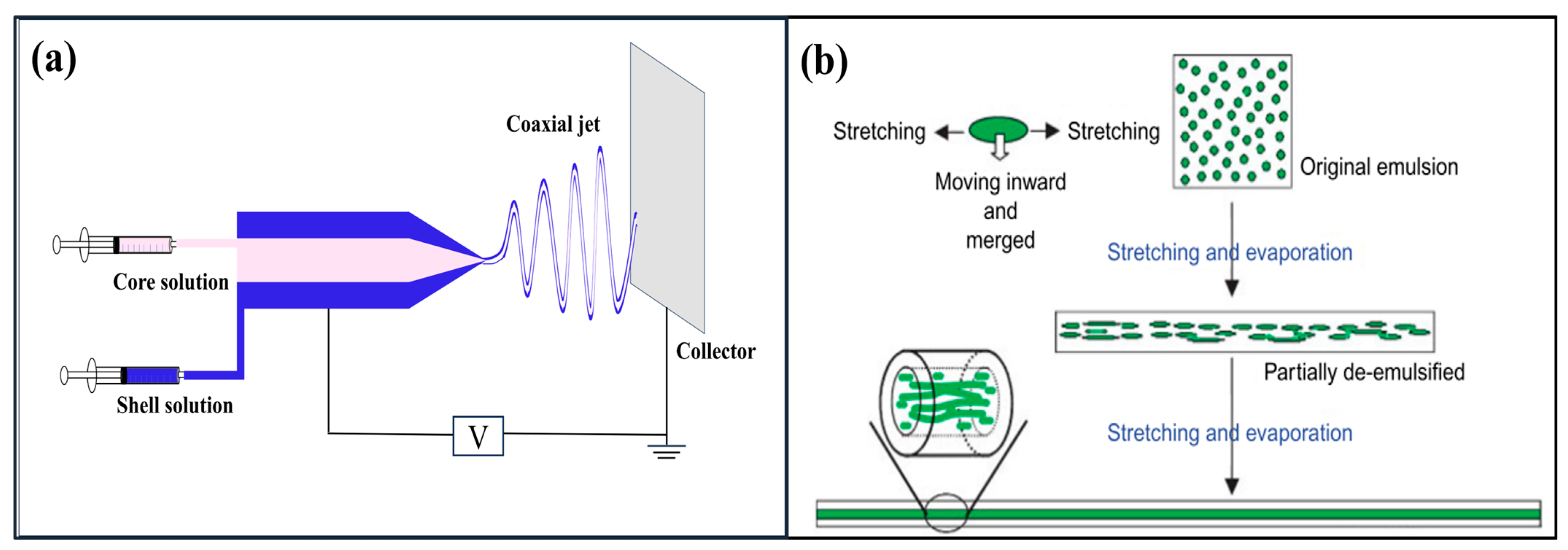
Nanofibers with a core–shell structure are fabricated using two distinct types of materials for the core and sheath in a way that a well-defined boundary separates both components. Coaxial electrospinning and emulsion electrospinning are two technically viable and economically feasible methods that are widely used for the preparation of core–shell nanostructure fibers (Figure 8) [3]. In the coaxial electrospinning process, two different polymer solutions are simultaneously delivered through a coaxial spinneret, consisting of two concentric hollow needles, driven by separate syringe pumps. This arrangement results in the generation of a coaxially charged jet. As the core and shell polymer solutions meet at the tip of the coaxial needle, the core solution becomes surrounded by the sheath solution, forming a compound Taylor cone when subjected to a high electrostatic field. Subsequently, the ejection of a coaxial jet occurs, leading to the production of core–shell nanofibers with distinct compositions for the core and shell [3].
Several important factors play a central role in generating continuous and uniform core–shell nanofibers [120,121,122]: (i) The miscibility of the solutions, as generating a stable coaxial jet is challenging when using two miscible solutions. Only immiscible and semi-miscible solutions can produce a stable coaxial jet. In semi-miscible solutions, the blending of both materials can occur at the interface of the core and shell solutions. (ii) The flow rates of both solutions should be carefully controlled to ensure that the inner fluid is fully surrounded by the outer fluid. The flow rates can have a significant effect on the shell thickness and core diameter. Nguyen et al. [123] reported a significant correlation between the core–shell solution flow rates, as well as the porosity and stability of core–shell fibers. Lower flow rate led to the production of a more stable core–shell structure with higher fiber porosity. (iii) Viscosities of the solution, as high viscosity can overcome the interfacial surface tension between the core and shell and form stable core–shell fibers [120]. Kaerkitcha et al. [124] observed that the viscosity ratio (outer/inner) affected the morphology of electrospun core–shell fibers. An increase in the viscosity ratio resulted in thicker walls. However, the core diameter decreased, and the overall fiber diameter increased with higher outer/inner viscosity ratios. The authors recommended maintaining the outer/inner viscosity ratio within the range of 1.22–2.82. (iv) Evaporation of solvent [121] is also a factor, as the morphology of the core and shell nanofibers is strongly influenced by solvent evaporation in both regions. When the evaporation rate in the shell solution exceeds that of the core solution, the fibers collapse and are unable to withstand atmospheric pressure. Conversely, a high evaporation rate in the core solution can create a vacuum within the core, ultimately causing fiber collapse under atmospheric pressure.
Core–shell nanofibers have attracted the attention of several authors due to their unique characteristics and wide range of applications [5]. For instance, this method is able to produce composites with desirable properties by taking advantage of the positive properties of each of the contributing sides (core and shell materials) [120]. Huang et al. [125] produced biodegradable composite membranes from polylactic acid (PLA) and PBS using coaxial electrospinning. The shell solution consisted of 20 wt.% PBS in hexafluoroisopropanol (HFIP)/chloroform (4/1 w/w), while the core solution was composed of 7 wt.% PLA in DCM/DMF (4/1 w/w). The resulting membranes exhibited a porous structure with interconnected pores. Also, the core–shell membrane displayed higher tensile strength and elongation at break compared to neat PBS and PLA membranes. These findings highlighted the complementary influence of PBS and PLA on the mechanical properties of the membranes. Furthermore, coaxial electrospinning allows for the production of nanofibers from non-electrospinnable materials [122]. In this method, a polymer solution that is effectively electrospinnable and has suitable viscosity is used as an outer solution to guide the core materials and produce nanofibers. Subsequently, neat fibers composed of the core materials can be obtained by extracting the shell polymer using an appropriate solvent [122]. One study by Sun et al. [84] reported that by using the coaxial electrospinning technique, nanofibers were produced from poly(dodecyl thiophene) (PDT) and a metal salt (palladium (II) diacetate (Pd(OAc)2)), for which neither was electrospinnable alone. Core–shell fibers of PEO/PDT and PLA/Pd(OAc)2 were fabricated by using PEO and PLA as templates for the formation of PDT and Pd(OAc)2 nanofibers, respectively.
For applications, core/sheath nanofibers are considered a suitable candidate in drug delivery applications due to their ability to generate homogeneous encapsulation of a wide variety of drugs, delay the onset of the initial burst release, and enable controlled sustained release [121]. For example, Mao et al. [126] reported that PLA/graphene oxide (GO) nanofiber membranes with a coaxial structure showed a lower release rate compared to single axial structure, and this coaxial membrane could suppress the initial burst release of the drug. In addition, this technique was explored for its potential applications in tissue engineering [127]. Core–shell membranes composed of poly(methyl methacrylate) (PMMA) and silk (SF) were fabricated using coaxial electrospinning [128]. The results indicated that cell adhesion and proliferation were more effective on PMMA/SF mats compared to neat PMMA. The SF shell enhanced cell affinity on the fiber surfaces, while the PMMA core provided mechanical support for tissue regeneration.
In emulsion electrospinning, core–shell nanofibers are directly produced by using a single needle [129]. Emulsions consist of two or multiple immiscible phases, where generally one phase is dispersed as drops in the other phase, making the continuous phase. Normally, the phase dispersed as the drop in the emulsion is converted into the core of the electrospun fibers and the continuous phase turns into the shell. Fabrication of core–shell fibers is performed by two types of emulsions: water-in-oil (W/O) or oil-in-water (O/W). For water-in-oil emulsions, the dispersed phase is based on the solution of a water-soluble polymer with dissolved polar and hydrophilic molecules. On the other hand, the continuous phase is formed by a hydrophobic polymer solution. In the case of oil-in-water emulsions, the dispersed phase is oil (mineral or vegetal) and the continuous phase is formed by the hydrophilic solution. This type of emulsion is used for the encapsulation of hydrophobic drugs. The process involves the fast evaporation of solvent from the region close to the surface, leading to a rapid increase in the viscosity of the outer layer compared to that of the inner layer. It also causes the drop to be incorporated into the inner layer. Subsequently, the drops are stretched into elliptical shapes along the axial direction of the fibers to form the core fibers [129]. For instance, Xu et al. [130] fabricated uniform core–sheath nanofibers via electrospinning of a water-in-oil emulsion. This emulsion comprises a water-based phase containing a poly(ethylene oxide) (PEO) solution with an oil-based phase made up of an amphiphilic poly(ethylene glycol)-poly(L-lactic acid) (PEG-PLA) diblock copolymer dissolved in chloroform. The resulting fibers had a PEO core surrounded by a distinct PEG-PLA sheath, creating a well-defined boundary between both components. Ma et al. [131] used emulsion electrospinning for the fabrication of natural polymer fibers that were challenging to electrospin. In their study, they initially created core–shell polycaprolactone/chitosan (PCL/CS) composite nanofibers through an emulsion system. Subsequently, ultrafine CS fibers were obtained by removing the PCL shell.
Figure 8.
Schematic representation of: (a) coaxial electrospinning; (b) emulsion electrospinning [130]. Reproduced with permission from Xu et al., Macromolecular Rapid Communications; published by Wiley, 2006.
Figure 8.
Schematic representation of: (a) coaxial electrospinning; (b) emulsion electrospinning [130]. Reproduced with permission from Xu et al., Macromolecular Rapid Communications; published by Wiley, 2006.
4.3. Hollow Fibers
Coaxial electrospinning is commonly used to produce fibers with hollow structures. In general, high-aspect-ratio hollow fibers are generated after electrospinning by removing the core from core–shell nanofibers. Core removal can be achieved through one of two methods: core extraction or core decomposition. In the first method, the core materials are selectively dissolved by the solvent. There is therefore a limitation in selecting the polymer for the core and shell. The second method involves heat treatment to eliminate the core material. Similar to any extraction method, the choice of the polymer for the shell is limited because it must remain stable during the decomposition of the core material [120]. Lee et al. [132] produced continuous uniform nanofibers with a hollow structure via coaxial electrospinning with an inner silicon oil and outer polymer solutions. For this purpose, poly(methyl methacrylate) (PMMA) dissolved in formic acid (FA) was chosen as the shell solution, while silicon oil was chosen as core fluid, and n-hexane was used as the solvent to remove the mineral oil. The effect of concentration and dielectric constants of the solvent was also studied. It was found that increasing the concentration increased the fiber diameter, but increasing the dielectric constants slightly decreased the diameter while the wall thickness of the hollow fiber substantially decreased. They also used polycarbonate (PC) for the shell solution and showed that increasing the polymer molecular weight increased the wall thickness and the overall diameter of hollow fibers. However, the wall thickness decreased when the viscosity of the inner silicon oil decreased. In another study by Lee et al. [133], coaxial electrospinning was used to produce hollow carbon nanofibers. Poly(acrylonitrile) (PAN) solutions were set as the shell liquid, while poly(styrene-co-acrylonitrile) (SAN) solutions were used as the core liquid. This process, followed by heat treatment, led to PAN in the shell being carbonized while the core component (SAN) was degraded and eliminated. A careful study on the three different core components revealed that SAN was highly suitable for the sacrificial core. SAN exhibited good coaxial electrospinnability for fabricating uniform core–shell nanofibers due to its immiscibility with PAN. In addition, SAN had excellent thermal stability, preventing shell shrinkage and preserving the shell structure.
4.4. Porous Structure
The production of electrospun nanofibers featuring a porous structure offers a substantial improvement in the specific surface area of the resulting nanofibers [8,134]. This expanded surface area makes them suitable for a diverse array of applications, including filtration, tissue engineering, drug delivery and release. Four methods based on different mechanisms have been introduced for the pore formation within electrospun structures.
- (i)
- Breath figure: This mechanism is based on condensing water vapor on a cold surface during electrospinning [135]. As the solvent evaporates, it cools the fiber’s surface, leading to the condensation of water vapor. Then, the condensed water droplets create pores on the fiber’s surface and these pores become more pronounced as the water droplets evaporate. This mechanism requires high relative humidity and a significant temperature decrease. This is why volatile solvents (DCM, CF and THF) are used. Furthermore, this method is mainly used for hydrophobic polymers such as PS, PMMA, and PLA [135]. Huang and Thomas [136] produced porous PLA electrospun fibers using a chloroform (CF) solution. Circular pores were visible only on the fiber’s surface and not inside. They tested different solvents including acetone (ACe) and CF and found that CF, a water-immiscible solvent, created porous fibers, while ACe, a water-miscible solvent, resulted in smooth fibers. Water-immiscibility significantly affected the fiber morphology.
- (ii)
- Vapor-induced phase separation (VIPS): This process runs when a nonvolatile solvent slowly evaporates during electrospinning, allowing time for water vapor to diffuse into the charged jet [135]. The water vapor causes a liquid–liquid phase separation within the jet, resulting in an internal porous structure. VIPS is typically used for hydrophobic polymers dissolved in water-miscible solvents at high relative humidity. The low volatility of the solvent and environmental humidity are critical factors influencing the fiber’s structure [135]. Zheng et al. [137] fabricated electrospun porous PS fibers from a 25% PS/DMF solution at 60% relative humidity. They observed that the solvent properties and humidity levels were critical factors in shaping the fibers. The low volatility of DMF allowed water molecules to penetrate the polymer/solvent jet, leading to the formation of a porous structure through separation of the polymer-rich and polymer-lean phases.
- (iii)
- Non-solvent-induced phase separation (NIPS): This method creates porous fibers by combining a non-solvent with a polymer solution [138]. It is crucial to select a non-solvent with lower volatility than the solvent. The mixture forms a polymer-rich phase with most of the polymer and some solvent, as well as a polymer-lean phase with a blend of the remaining solvent, non-solvent, and a small portion of polymer. The polymer-lean phase evaporates during electrospinning, forming a porous structure, mostly on the surface [138]. Unlike the challenges of the breath figure method, NIPS offers better control, resulting in more uniform porous fibers and overcoming the issues of variable fiber diameter caused by low solvent dielectric constants [136]. Huang and Thomas [136] examined the changes in fiber morphology when varying the concentration of ethanol (EtOH) in PLA/CF. Using different EtOH content (5%, 10%, 20% and 30% v/v), they observed that 5% v/v EtOH produced elliptical pores on the surface. Increasing the EtOH content led to a transition from surface pores to a scalloped surface (shallow surface pores connected by ridges), eventually resulting in a smooth surface with some wrinkles. This progression was as follows: porous surface → scalloped surface → smooth fibers with minor wrinkles. Notably, all these fibers had a non-porous interior. They attributed these findings to the NIPS mechanism. The transition from scalloped to smooth surfaces was due to water droplets expanding on the fibers’ surface in a humid environment with high water–EtOH-miscibility.
- (iv)
- Thermally induced phase separation (TIPS): This method takes place when the electrospun jet faces a substantial temperature decrease during its travel to the collector [135]. The driving force to produce the porous structure is the temperature difference. Ye et al. [139] achieved a highly porous structure by integrating a high-temperature electrospinning process into a thermally induced phase separation. They increased the spinning solution temperature to 200 °C and the hot jet was quickly cooled as it reached the collector, leading to a thermally induced phase separation. This method produced porous fibers with over a 100-fold increase in specific surface area, which is a precise way of forming pores.
5. Electrospun Nanofibers Materials
Electrospinning is a versatile technique for producing nanofibers from various materials, including polymers, small molecules, and sol-gels [140]. Among these materials, organic polymers are commonly used. The introduction of nanoscale components, such as nanoparticles, nanosheets, and nanotubes into polymer solutions offers a wide range of possibilities to produce composite nanofibers. The following section will discuss the different types of nanofibers obtained via electrospinning, including polymeric, non-polymeric, and carbon nanofibers.
5.1. Polymeric Nanofibers
Success in electrospinning organic polymer solutions depends on various factors, including the polymer’s properties, solvent choice, processing conditions, and environmental factors. To ensure effective solution electrospinning, two essential conditions are vital: (i) the polymer must have a suitably high molecular weight, and (ii) there must be an appropriate solvent to dissolve the polymer. Polymer molecular weight controls the solution rheology, as lower Mw favors beads formation over fibers due to limited chain entanglement [140]. A uniform solution depends on the solvent solubility parameters, but high solubility does not guarantee electrospinning suitability [141,142]. Solvent volatility affects the evaporation and jet solidification rates, but excessive volatility leads to premature solidification (needle blockage) and low volatility causes wet fibers (residual solvent). A variety of solvents, including chloroform (CF), alcohols (al), dimethylformamide (DMF), dichloromethane (DCM), tetrahydrofuran (THF), dimethyl sulfoxide (DMSO), acetone (ACe), trifluoroethanol (TFE), and hexafluoroisopropanol (HFIP), are commonly used to dissolve organic polymers. The selection of the right solvent system is important for its specific application.
Several polymers, both natural and synthetic, have been successfully used in solution electrospinning, including natural biopolymers (chitin, chitosan, alginate, collagen), synthetic polymers (polystyrene (PS), poly(vinyl chloride) (PVC)), biocompatible and biodegradable polymers (poly(lactic acid) (PLA), polycaprolactone (PCL), poly(lactic-co-glycolic acid) (PLGA)), conductive polymers (polyaniline (PANI), polypyrrole (PPy)), and functional polymers (poly(vinylidene fluoride) (PVDF)) [140]. The following section focuses on biopolymers used for sustainability reasons.
5.1.1. Natural Polymers
Natural polymers can be sourced from a diverse range of origins, including plants, animals, and microorganisms [143]. These materials are highly sought because they are renewable resources. This is why researchers have undertaken extensive research for the development of electrospun nanofibers suitable for biomedical applications [144], filtration [145], and food packaging [146]. The main objective in selecting natural polymers for electrospinning is to achieve the highest level of biocompatibility, closely mimicking the extracellular matrix (ECM) in its original state. Additionally, some of these natural polymers have anti-inflammatory and antimicrobial properties, such as chitosan [143] and polycurcumin [147]. In general, electrospinning natural polymers is challenging due to their low stability. Blending them with synthetic polymers enhances mechanical strength, making them more suitable for various applications [143]. Two types of biobased polymers are used: (i) polysaccharides such as chitosan, alginate, and cellulose, and (ii) proteins such as collagen and gelatin.
Polysaccharide-Based Polymers
- Chitosan
Chitosan is mainly obtained from the partial N-deacetylation of chitin with the molecular formula (C6H11NO4)n, along with the chemical name (1,4)-2-amino-2-deoxy-β-D-polyglucose. Chitin, the second most abundant natural polysaccharide following cellulose, is widely found in the exoskeletons of sea animals, insects, and microorganisms. Due to its prevalence in these biological sources, chitosan is considered a resource-rich material [148]. Chitosan shows outstanding biocompatibility, full biodegradability, and minimal toxicity. Therefore, chitosan-based materials have attracted research attention across different fields such as wound dressing, tissue engineering, wastewater treatment, and air filtration. However, the fabrication of electrospun chitosan nanofibers with uniform morphology is a challenging task due to its low solubility, polycationic charge, high viscosity, high crystallinity, and high-intensity hydrogen bond [149]. To overcome this problem, researchers have investigated suitable methods of overcoming these shortcomings for the purpose of electrospinning. One possibility is blending with other polymers or adding metal nanoparticles [148]. For example, Darbasizadeh et al. [150] reported that the introduction of poly(ethylene oxide) (PEO) into a chitosan solution improved chain entanglement and the spinnability of the solution. This enhancement was attributed to the formation of hydrogen bonds between the polyether oxygen in PEO and the amine group in chitosan. The result revealed that the successful production of uniform nanofibers with an average diameter of 80 nm was achieved with a chitosan–PEO weight ratio of 6:4. Subsequent crosslinking with tripolyphosphate resulted in composite nanofibrous structures with suitable drug delivery abilities. In another study, biocompatible chitosan/PVA nanofibers were fabricated using electrospinning [151]. The results indicated that as the PVA content increased, the number of beads decreased, and the formation of fibers occurred more gradually. When the chitosan–PVA ratio reached 50:50, all the beads disappeared, and uniform fibers were achieved. Thus, the polymer composition significantly influenced the morphology and diameter of electrospun nanofibers. The resulting electrospun fibrous mat showed potential as scaffolding material for skin regeneration [151]. Moreover, Pan et al. [152] developed chitosan/PEO@MOF-5 composite nanofiber membranes via co-electrospinning. The mechanical properties of the chitosan-based membrane were improved by the introduction of a stable metal organic framework (MOF-5). In addition, the membrane showed an excellent filtration performance for PM2.5, achieving a filtration efficiency of 99.95% while keeping a minimal pressure drop.
- Alginate
Alginate is an anionic polysaccharide derived from dark and brown algae, composed of (1,4)-linked β-D-mannuronate (M) and α-L-guluronate (G) residues, resulting in a linear unbranched copolymer structure. Alginate is non-toxic, biocompatible, cost-effective, non-immunogenic, and has high absorption capacity, making it popular in biomedical applications such as drug delivery and tissue engineering [153]. However, challenges exist in obtaining continuous and uniform nanofibrous structures from pure alginate solutions via electrospinning, as no successful report has been found to date [154]. Alginate’s inability to form nanofibers via electrospinning is attributed to factors such as its electrical conductivity, high surface tension, and lack of molecular entanglement. Researchers have studied different strategies to improve alginate’s electrospinnability, using carrier polymers, modifying alginate, and using co-solvents and surfactants [155]. For example, Daemi et al. [156] developed the fabrication of alginate-based nanofibers via solution electrospinning by sulfation of the hydroxyl functional groups of alginate (alginate modification) and blending with PVA. In another study, alginate-based membranes composed of sodium alginate (SA) and poly(vinyl alcohol) (PVA)-encapsulating antimicrobial agents such as moxifloxacin hydrochloride (MH) were fabricated by electrospinning and showed good potential for wound dressing applications [157].
- Cellulose
Cellulose, the most prevalent natural polymer in the world and found in nearly all plant structures, has attracted significant attention due to its abundance, renewability, biodegradability, and impressive physico-chemical characteristics [158]. However, electrospinning of cellulose is difficult due to its resistance to dissolve in common solvents. Finding a suitable solvent for electrospinning is challenging because of the cellulose’s strong intermolecular and intramolecular hydrogen bonds [159]. A blend of lithium chloride and N,N-dimethylacetamide (LiCl/DMAc) is a common solvent for the electrospinning of cellulose, but its effectiveness can vary based on factors such as cellulose source, molecular weight, and crystallinity [158]. Chen et al. [160] proposed pre-activated cellulose with monohydric alcohols before dissolution as an effective method to improve the fiber quality from LiCl/DMAc solvent. Alternative solvents, such as trifluoroacetic acid (TFA) [161] and N-methylmorpholine-N-oxide (NMMO) [162], were used, offering unique advantages and challenges for electrospinning, but provided options for different cellulose applications. Additionally, ionic liquids (IL) are emerging as a potential eco-friendly replacement for traditional solvents in cellulose dissolution due to their high thermal and chemical stability and simple recycling process [158]. Ionic liquids’ polar nature, low vapor pressure, and interaction with cellulose hydroxyl groups make them attractive for cellulose dissolution. However, a pure cellulose solution in ionic liquid is not easily electrospun due to its high viscosity and low volatility. Therefore, co-solvents, such as dimethylformamide (DMF) and N,N-dimethylacetamide (DMAc), are introduced alongside ionic liquids to enhance spinnability by lowering viscosity and increasing partial polarity [163].
Cellulose derivatives, such as cellulose acetate (CA), cellulose acetate butyrate (CAB), and ethyl cellulose, were also dissolved in common solvents and introduced as substitutes to address the challenges associated with cellulose electrospinning [158]. For instance, Dos Santos et al. [161] reported on the fabrication of CA scaffolds loaded with annatto (a natural dye from tropical plants). Their findings revealed that these nanofibers not only stimulated the proliferation of fibroblast cells, but also facilitated their spreading and penetration within 48 h. Additionally, the bioactive compounds present in the material had the ability to regulate the inflammatory process in vitro, suggesting its potential for wound healing applications. In another study, core–shell nanostructures were created using a thin layer of CA to coat a drug protein [164]. The results revealed that these core–shell nanofibers exhibited a linear/cylindrical morphology with diameters ranging from 0.66 to 0.87 μm. More importantly, they displayed distinct core–shell configurations with a shell thickness varying from 1.8 to 11.6 nm. The initial rapid release of ibuprofen typically observed in monolithic drug–protein composites was mitigated due to the CA coating. Furthermore, this coating allowed for precise control of the drug release rate, achieving a 90% release rate within a customizable timeframe ranging from 23 to 44 h.
Protein-Based Polymers
- Collagen
Collagen is composed of 90% of the protein in humans. It shows favorable properties for cell attachment due to its easy degradation and absorption by the human body [165,166]. However, pristine collagen fibers have some drawbacks, including poor thermal stability, limited solvent resistance, and low mechanical strength, limiting its range of applications. Consequently, collagen is frequently used as a composite material and blended with other substances, including ceramics and synthetic polymers [165,166]. Rath et al. [167] reported on the fabrication of nanofibrous collagen mats loaded with silver nanoparticles (AgNP) using electrospinning. The results revealed that these composite nanofiber mats showed favorable wound-healing effects due to their intrinsic antibacterial and anti-inflammatory properties, as well as a controlled drug release profile achieved through the successful incorporation of AgNP. In another study [168], collagen and PLLA were mixed at a 3:7 ratio to fabricate membranes with both aligned and randomly oriented fibers. The presence of collagen had several effects: it influenced fiber orientation and reduced fiber diameter (from 439 to 259 nm). Additionally, the water contact angle decreased in the collagen/PLLA electrospun material, which was attributed to the hydrophilic groups of collagen. Finally, the study also indicated that the membranes based on aligned fibers showed higher crystallinity and mechanical performance. More importantly, they also promoted the proliferation of human fibroblasts. Ribeiro et al. [169] fabricated collagen/nano-hydroxyapatite (nHA) nanocomposite scaffolds using simultaneous electrospinning and electrospraying techniques to mimic bone ECM. The findings revealed that the scaffolds showed elastic moduli between 0.3 and 2 GPa with 30 nm fiber diameter. Additionally, both collagen and biocomposite mats were non-cytotoxic and effectively supported osteoblast adhesion. However, osteoblasts cultured on neat electrospun collagen nanofibers displayed lower levels of metabolic activity compared to those cultured on biocomposite ones. The incorporation of nHA into type I collagen scaffolds significantly promoted osteoblast proliferation after 4 days of cell culture. This membrane showed great potential to treat bone defects by guiding bone tissue regeneration and addressing bone diseases.
- Gelatin
Gelatin, derived from collagen by hydrolysis, is found in animal skin, ligaments, cartilage, and bone [170]. The ability of gelatin fibers to mimic the extracellular matrix (ECM) structure of human tissues, coupled with their excellent biocompatibility, biodegradability, and widespread commercial availability, makes them suitable for a range of applications. These include drug delivery and tissue engineering [170,171]. Gelatin, being soluble in water, faces challenges in electrospinning due to substantial hydrogen bonding [170]. To address this issue, combination with other polymers is used as a simple strategy to produce gelatin-based nanofibers [172]. Zangh et al. [173] fabricated gelatin/PCL composite membranes via electrospinning with improved mechanical properties and enhanced wettability. These membranes served as promising scaffolds for bone marrow cell culture, demonstrating favorable cell attachment, growth, and migration within the scaffold. The addition of acidic solvent to gelatin and its blends was also shown to facilitate nanofiber production [172]. Okutan et al. [174] dissolved gelatin in 20% (v/v) acetic acid aqueous solution and fabricated bead-free and smooth fibers with diameters in the range of several tens of nanometers. Furthermore, different organic solvents, such as trifluoroacetic acid (TFA), trifluoroethanol (TFE), and hexafluoro isopropanol (HFIP), were used as a solvent for electrospun gelatin [172]. Huang et al. [175] introduced TFE as an effective solvent with a concentration of 5% (w/v) showing excellent spinnability and yielding the smallest fiber diameter (100 nm).
5.1.2. Synthetic Biodegradable Polymers
Innovative technologies centered around biobased and biodegradable polymers hold significant promise in reducing our dependence on fossil fuels and alleviating the global burden of plastic waste and pollution [176,177]. These polymers play a pivotal role in addressing multifaceted challenges related to the environment, public health and sustainability, which have long been associated with traditional synthetic (petroleum-based) polymers.
Among the various options, degradable polyesters, such as PCL, PLA and PBS, have received substantial attention due to their intrinsic biodegradability, origins in renewable resources, scalability in production, and versatility for diverse applications [178]. Notably, these synthetic materials can be efficiently electrospun and have found wide-ranging uses in biomedical [179], air filtration [180], and food packaging industries [181].
Polycaprolactone (PCL)
PCL is a semi-crystalline polyester synthesized via ring-opening polymerization of ε-caprolactone with catalysts [171,182]. Under physiological conditions, PCL undergoes degradation via the hydrolysis of its ester linkages, which occurs at a slower rate. Due to its exceptional properties and the possibility to adjust its biodegradation rates, PCL has gained significant recognition for a wide range of applications [183]. These applications span various fields, including drug delivery systems, scaffolds for tissue engineering, and implantable biomaterials. To overcome the challenges associated with its slow degradation and limited mechanical properties, PCL can be combined with other polymers or nanomaterials to create composites, copolymers or blends. For instance, electrospun PCL composite scaffolds loaded with silica nanoparticles (Si-NPs) were fabricated for bone regeneration [179]. The results revealed that Si-NPs were uniformly distributed inside the PCL electrospun fibers, leading to the tensile strength improving by more than two folds. Furthermore, the scaffolds showed cytocompatibility. In another study, coaxial electrospinning was used to encapsulate bovine serum albumin (BSA), along with poly(ethylene glycol) (PEG) within PCL [184]. This core–sheath structure significantly reduced the initial burst release. By using this core–sheath structure, the possibility of direct contact with bioactive agents or exposure to organic solvents was substantially decreased. This protective mechanism served to prevent any loss of BSA activity.
Polylactic acid (PLA)
PLA, an aliphatic thermoplastic polyester, can be derived from annually renewable resources. It is typically synthesized through either a simple polycondensation reaction or the ring-opening polymerization of lactide monomers. Lactic acid, the precursor, has a chiral carbon, resulting in two enantiomeric forms: L-lactic acid and D-lactic acid. Consequently, poly(lactic acid) encompasses a group of polymers, namely poly-L-lactic acid (PLLA), poly-D-lactic acid (PDLA), and poly-D,L-lactic acid (PDLLA). PLLA and PDLA show crystalline properties, while PDLLA is completely amorphous [185]. It is important to note that PLA is a polymer whose stereochemical structure can be readily modified by controlling the mixture of enantiomeric forms during the polymerization process, enabling the production of high-molecular-weight amorphous or crystalline polymers [186]. Additionally, PLA is seen as a promising biopolymer that is suitable as a substitute for conventional petrochemical-based polymers in industrial applications due to its biocompatibility, biodegradability, good mechanical properties, and processability [187]. However, PLA tends to be brittle at room temperature, resulting in a low elongation at break. This limitation restricts its use in applications requiring high elongation or mechanical toughness. To address this issue, blending was introduced as a simple method to enhance the elongation at break and tensile toughness without adversely affecting the tensile strength and tensile modulus [188]. PLA stands out as one of the most extensively researched and used synthetic aliphatic polyesters within the field of electrospinning, owing to its promising properties. Electrospun nanofibers based on PLA show great potential across a wide range of applications, including tissue engineering scaffolds, drug delivery systems, and wound healing applications [189], filtration processes [180], and packaging solutions [181]. In one study, calcium oxide nanoparticles (n-CaO) sourced from eggshell waste were incorporated into PLA and electrospun to produce PLA/n-CaO scaffolds showing potential for bone tissue regeneration [190]. The presence of n-CaO significantly improved the mechanical properties by increasing the Young’s modulus (122–138%) compared to neat PLA fibers. Moreover, n-CaO introduced both bioactivity and antimicrobial properties, improving the overall biological performance of the PLA matrix. In the context of drug delivery applications, a study by Mao et al. [126] involved the fabrication via coaxial electrospinning of PLA/graphene oxide (GO) nanofiber membranes for drug release. The drug release performance was assessed using an organic dye, Rhodamine B (RhB), as a model drug. The results showed that GO addition significantly enhanced the release of RhB from the nanofibers. Based on these findings, it can be concluded that PLA/GO nanofiber membranes hold great promise for drug delivery systems. In the context of filtration applications, Wang et al. [180] reported that electrospun porous bead-on-string PLA nanofibrous membranes were produced by controlling the solvent composition and concentration of the polymer solution. The filtration performance of the resulting membranes was investigated by measuring the penetration of sodium chloride (NaCl) aerosol particles. The thin nanofiber and nanopore on the beads contributed to excellent air filtration performance. In the context of food packaging, Feng et al. [191] conducted a study where they fabricated an electrospun nanocomposite mat based on PLA/TiO2 with a TiO2 nanoparticle content of 0.75 wt.%. PLA, in its pristine form, does not display inherent biological activity. Nevertheless, adding TiO2 as an active agent with antibacterial properties increased the PLA functionality.
Poly(butylene succinate) (PBS)
Poly(butylene succinate) is another biodegradable aliphatic polyester synthesized through the polymerization of two monomers: succinic acid (SA) and 1,4-butanediol (BD). It can be 100% biobased depending on the origin of the monomers, i.e., whether they are derived from fossil resources or bacterial fermentation [192]. PBS is a semi-crystalline polymer with a glass transition temperature (Tg) around −32 °C. Its mechanical and thermal properties are related to its crystal structure and degree of crystallinity [193]. Another notable characteristic of PBS is its compostability, a feature that when combined with its mechanical resistance, ductility, toughness, and impressive impact resistance positions PBS as a promising material for sustainable applications [194]. In recent years, PBS has attracted significant attention in both industrial and scientific fields, especially in the context of preparing electrospun nanofibers for a wide range of applications [195]. Keratin–PBS electrospun mats were fabricated for drug delivery and cell growth scaffolds [196]. Despite keratin and PBS’s natural incompatibility, blending them in equal proportions allowed successful electrospinning, resulting in finer and more uniform nanofibers than PBS alone. The introduction of keratin into PBS improved its mechanical properties, while maintaining its advantages. The nanofibers retained high swelling capacity and facilitated diclofenac permeation under physiological conditions. Additionally, these mats supported significant fibroblast adhesion and growth, making them promising cell growth scaffolds. In another study [197], antimicrobial mats made from PBS were developed by incorporating natural food-grade agents using blend electrospinning. These agents consisted of edible gums (arabic, karaya, tragacanth), essential oils (coriander, lavender), and a free fatty acid (linoleic acid). The inclusion of these agents not only conferred antimicrobial properties, but also enhanced the mechanical properties of PBS mats, bringing them closer to the performance of human skin. Notably, the PBS mats showed high biocompatibility when tested with mouse fibroblasts. Recently, auxetic (having a negative Poisson ratio) electrospun PBS membranes were produced by the careful control of processing conditions to achieve an appropriate degree of fiber orientation and, leading to this unique feature in PBS membranes [198].
PBS was also used in combination with other polymers, resulting in materials having favorable properties based on both polymers, ultimately improving their overall performance [199,200]. Phiriyawirut et al. [199] investigated the fabrication of porous electrospun nanofibers by blending PLA and PBS. Round fibers with pores on the surface were produced from PBS (17% (w/v)) and PLA (17% (w/v)) in DCM/DMF at different PLA/PBS ratios (16 kV and 18 cm of distance). Increasing the PBS content in the blend led to lower fibers diameter, while the shape of the pores on the surface changed from round to oval. For the thermal properties, adding PBS increased the glass transition temperature (Tg) of PLA, but the melting temperature (Tm) of the electrospun nanofibers did not change. The PLA/PBS nanofibers at a blend ratio of 95/5 showed the best tensile properties, while the Young’s modulus was increased compared to the neat electrospun fibers.
5.2. Carbon Nanofiber
One class of materials that can be produced through electrospinning is carbon nanofibers, which find applications in various fields such as energy conversion and storage, catalysis, sensors, adsorption, and biomedical [201]. Carbon nanofibers, with submicron and nanometer size, can be synthesized using a solution electrospinning method involving a sequence of three key stages [3,202]. Initially, a polymer or a polymer blend is subjected to electrospinning to produce the fibers. It is important to note that the diameter, morphology, and porosity of the precursor nanofibers have a direct effect on the properties of the resulting carbon nanofibers. In cases in the precursor nanofibers have a porous structure, there is a possibility that these pores may be retained in the final carbon nanofibers. Subsequently, the electrospun fibers are subjected to thermal treatment in air, typically at temperatures ranging from 200 to 300 °C. This process transforms the polymer into a ladder-like compound, imparting stability to the fibers and allowing for further processing at higher temperatures [203]. This stabilization turns the thermoplastic precursor nanofibers into dense thermosetting polymers through intricate physical and chemical reactions (cyclization, dehydrogenation and polymerization) [202]. A slow heating rate is important to prevent the polymer from melting, thereby preserving the fibrous structure during subsequent carbonization. Additionally, applying external tension can help to maintain the preferred molecular orientation along the fiber axis and prevent fiber shrinkage during stabilization. Lastly, the stabilized fibers are subjected to carbonization in a controlled inert gas atmosphere [3]. This process takes place at temperatures ranging from 400 to 1800 °C. It results in the production of carbon fibers containing more than 90% carbon content, while selectively removing non-carbon elements in a gaseous form without compromising the fibrous morphology. Additionally, carbonization converts the ladder structure to a graphite-like one, decreases the polymer fibers’ diameter, increases the surface area, and enhances conductivity. In some cases, an additional graphitization process is applied at extremely high temperature (up to 3000 °C) to further eliminate heteroatoms, promoting the growth of graphitic layers and increasing the stacking order of the material.
To obtain carbon nanofibers with desired properties, the selection of a suitable precursor polymer is important. Polyacrylonitrile (PAN) is the most widely used precursor due to its outstanding properties, including high carbon yield (>50%), spinnability, and commercial viability [3,202]. Carbon nanofibers made from electrospun PAN show superior mechanical properties. Arshad et al. [204] successfully produced robust carbon nanofibers with diameters ranging from 150 to 500 nm and lengths extending to centimeters when using PAN as the precursor. Individual nanofibers carbonized at 1400 °C exhibited a tensile strength of 3.5 ± 0.6 GPa with an elastic modulus of 172 ± 40 GPa. These impressive mechanical properties were achieved by optimizing the electrospinning parameters for the production of strong PAN nanofibers, as well as by selecting the optimal stabilization and carbonization temperatures. However, PAN is based on fossil fuel resources. Besides PAN, several other types of polymers were explored for the production of carbon nanofibers, including poly(vinylidene fluoride) (PVDF) [205], poly(vinyl alcohol) (PVA) [206], polyphenylsilane (PPS) [207], and pitch [208].
Today, renewable resources are being investigated. Lignin, an abundant natural polymer, represents an affordable option as a precursor material for the production of versatile carbon fibers. Lignin can convert to carbon fiber with diameters as fine as 200 nm, but its carbon conversion efficiency remains relatively low (20–40%) [3]. Lallave et al. [209] reported on the production of both solid and hollow carbon fibers from lignin using co-electrospinning, without the need for additional polymers. This process yielded remarkably fine carbon fibers, as small as 200 nm in diameter, displaying a smooth surface without defects. These carbon fibers comprised finely crystallized carbon structures, predominantly oriented along the fiber axis.
5.3. Non-Polymeric Nanofibers
Metallic and ceramic nanofibers, both non-polymeric in nature, can be produced through via electrospinning [3]. To generate metallic nanofibers, two main methods are available: direct electrospinning and deposition onto the surface of as-spun polymer nanofibers [210]. When composite nanofibers are generated via direct electrospinning, a two-step process is needed. First, calcination in the presence of air is used to eliminate the polymer component from the as-spun composite nanofibers, resulting in the formation of metal oxide nanofibers. Subsequently, a reduction step takes place in a reduced atmosphere to transform the metal oxides into metallic nanofibers. In this method, the concentration of the metal precursor plays a crucial role in determining the nanofiber’s structure [140]. It is essential to maintain sufficient concentration to prevent nanofiber breakup during the heat treatment. Additionally, the choice of carrier polymer is of the utmost importance. The polymer selected should be compatible with the metal precursor and should be easily removed through thermal treatment. Another influential factor is the thermal treatment conditions, including temperature, duration and atmospheric conditions, which can significantly affect the nanofiber diameter. Different metal nanofibers, including Fe, Co, Ni and Pt, were produced by this direct method [3]. For instance, to create smooth and pure nickel metal nanofibers, a sol-gel solution containing nickel (II) acetate (NiAc), and polyvinyl alcohol (PVA) was electrospun, forming PVA/NiAc nanofibers [211]. These nanofibers were then dried and subjected to calcination at 700 °C for 5 h with a heating rate of 2.3 °C/min in an argon (Ar) atmosphere. During this process, the PVA was completely removed and the NiAc decomposed, resulting in pure nickel metal nanofibers with an average diameter of 120 nm.
In the indirect method of producing metal nanofibers through electrospinning, the process involves coating electrospun fibers with a thin layer of metal using standard thin-film deposition techniques such as thermal evaporation, electron beam evaporation, or magnetron sputtering [212]. In the subsequent step, the polymer templates are removed by immersion in water or other organic solvents. As a result, the metallic nanofibers typically display a hollow-shaped cross-section. This method was used to fabricate fibers based on a wide range of metals, including Au, Ag, Cu, Pt, Al, Cr, Ni, and their various alloys, forming a network of nanofibers [212].
Ceramic nanofibers can also be produced through the electrospinning of a homogeneous precursor solution [210]. This solution comprises a blend of polymers with an inorganic sol-gel precursor. The initial step involves the creation of as-spun composite nanofibers. Subsequently, calcination at elevated temperatures is performed to achieve the desired ceramic phase while simultaneously eliminating the organic components. As an example to fabricate anatase TiO2 nanofibers, one of the most commonly synthesized electrospun metal oxide materials, a precursor solution was initially prepared [213]. This solution comprised polyvinyl pyrrolidone (PVP) as the polymer matrix and titanium tetraisopropoxide (Ti(OiPr)4) as the inorganic component. Electrospinning resulted in the formation of as-spun TiO2/PVP fibers with an average diameter of 79 ± 9 nm. Subsequently, to produce anatase nanofibers, the as-spun fibers underwent calcination in air at 500 °C for 3 h. This thermal treatment led to a reduction in fiber diameter (53 ± 8 nm). This reduction was mainly attributed to the removal of the PVP component and the densification of the TiO2 material. The resulting anatase nanofibers displayed fused TiO2 nanoparticles, each measuring about 10 nm in diameter, with observable voids between adjacent nanoparticles [213].
It is worth noting that the diameter and morphology of ceramic nanofibers can be influenced by various factors, including the diameter and composition of the composite nanofibers and the conditions during calcination [213,214]. For example, Kumar et al. [214] showed the formation of highly crystalline hierarchical TiO2 nanostructures with diverse morphologies. These morphologies ranged from one-dimensional regular fibers to porous rods, hollow tubes and spindles. These structures were achieved by controlled annealing of the electrospun TiO2/composite fibers at temperatures between 400 and 800 °C. Furthermore, through careful control of the precursor concentration in the polymeric solution, unconventional morphologies, such as flowers, rice grains, multi-channeled fibers and others, were also synthesized for various applications. For instance, Kumar et al. [215] synthesized flower-shaped SnO2 structures using electrospinning by precisely controlling the precursor concentration in a polymeric solution. These flower-shaped structures were composed of nanofibrils with diameters of 70–100 nm. Within these fibrils, linear arrays of single crystalline nanoparticles (20–30 nm) were found. These flower-shaped SnO2 nanostructures showed exceptional characteristics, including high crystallinity and substantial specific surface area, as well as improved electron density, diffusivity, and mobility compared to conventional fibers. As a result, these flower-shaped SnO2 fibers were used to fabricate high-performance dye-sensitized solar cells.
So far, various ceramic nanofiber compositions have been studied for different applications. These include CuO-ZnO composites [216], ZrC/SiC nanofibers [217], and SiO2 nanofibers/Al2O3 composites [218], as well as nanoparticles for water treatment and purification, electromagnetic interference (EMI) shielding materials and separators for lithium-ion batteries (LIB).
6. Fillers
By incorporating organic or inorganic nanoparticles into electrospun nanofibers, nanocomposite materials produced via electrospinning can show distinctive multifunctionality and remarkable attributes [219,220]. These properties give them a wide range of desirable performances that are well-suited for various applications such as filtration, catalysis, sensing, energy storage, and biomedical purposes Additionally, electrospinning has been shown to be a convenient technique for facilitating the self-assembly, effective orientation, dispersion, and alignment of nanoparticles.
Electrospun nanocomposite fibers are generated by two main approaches [220]. The first one involves the production of fibers indirectly, following the electrospinning process, through post-processing methods. This method is very useful when the nanoparticles are poorly dispersed in the initial solution or when large-scale fabrication is not possible. The second approach involves the direct production of the nanocomposites during electrospinning. In this method, the as-prepared nano-components are introduced and evenly distributed within the polymer solution. Subsequently, the nanocomposite fibers can be directly manufactured via electrospinning. This one-step technique has gained widespread popularity for the production of diverse nanocomposites using various types of nanoparticles [220]. In the following sections, specific types of nanoparticles suitable for electrospinning are presented and discussed.
6.1. Metal/Metal Oxide Nanoparticles
Metal and metal oxide nanoparticles have significant promise for various applications as they can improve the properties of electrospun fibers by modifying their chemical, optical, magnetic and conductive characteristics [220].
Silver nanoparticles (AgNP) are one of the important metallic materials [221]. Silver nanoparticles are known for their antibacterial properties, making them effective in biomedical materials. These nanoparticles also have the ability to scatter light and generate surface plasmon resonance, which is valuable in optical and photovoltaic materials for increasing light-related processes. PLGA/silver composite nanofibers were created via electrospinning [222]. The incorporation of AgNP into these composite nanofibers occurred without any alterations in their structure or chemistry. The dimensions of the nanofibers and AgNP ranged from 50 to 100 nm and 5 to 10 nm, respectively. According to the results, these nanofibers are a valuable choice as antimicrobial agents in biomaterials or water purification systems. In another study, Ag/PVP electrospun nanofibers with nonwoven, aligned and crossed patterns were fabricated using a coaxial electrospinning technique for potential use in advanced plasmonic solar cell devices [223]. The smallest diameter of the composite nanofibers led to the highest orientation of the Ag nanoparticles, resulting in increased conductivity and showing a surface plasmon resonance effect. In particular, the crossed or nonwoven patterns further enhanced high carrier mobility, compared to that of the aligned pattern, resulting in improving power conversion efficiency.
Gold nanoparticles (AuNPs) are another important metallic material often incorporated into electrospun fibers, owing to their antibacterial and biocompatible properties, distinctive plasmonic characteristics, exceptional electrical conductivity, and outstanding stability [220,224]. AuNP-loaded polyvinylpyrrolidone/ethylcellulose coaxial electrospun nanofibers were developed as promising scaffolds in the field of bone tissue regeneration [225]. AuNPs were successfully encapsulated into electrospun scaffolds, and their addition improved the porosity and mechanical properties. These scaffolds also showed excellent biocompatibility and osteogenic bioactivities. Manjumeena et al. [226] documented the fabrication of PVA-AuNP nanofibers with significant potential for cancer treatment and for antimicrobial wound dressings. PVA, known for its inherent hydrophilic properties, became even more hydrophilic with a very low loading of AuNPs. This increased hydrophilicity resulted in enhanced cell adhesion and proliferation. Additionally, these nanofibers displayed notable antiproliferative effects against cancer cells and showed promising antibacterial and antifungal activities. In another study [227], a flexible nonvolatile flash transistor memory device was introduced using a poly(ethylene naphthalate) (PEN) substrate and poly(3-hexylthiophene) (P3HT)-AuNP electrospun fibers as the channel material. Within this device, AuNPs served as localized charge traps distributed along the nanofiber channel, allowing for the programming and erase of the device, resulting in transitions between low-conductance (OFF) and high-conductance (ON) states when an electrical field was applied.
Metallic oxides, known for their superior chemical stability compared to pure metals, are gaining popularity in electrospinning [228]. This trend involves incorporating metallic oxide nanoparticles, such as SiO2, TiO2, MgO, ZnO and ZrO2 with varying sizes, into both hydrophobic and hydrophilic polymers [220].
Titanium dioxide nanoparticles (TiO2) are one of the most attractive metal oxides for improving textiles’ functionalities [229]. This is due to their distinct structural and electrical characteristics, photocatalytic self-cleaning, and antimicrobial activity, as well as their non-toxicity and cost-effectiveness. Sharma et al. [230] successfully produced porous PVP-TiO2 electrospun nanofibers with a suitable pore size (1.44 to 4.08 nm). These nanofibers showed versatility and held promise for a range of applications, including water filtration, air purification, and the production of protective masks designed to mitigate environmental hazards (COVID-19). A photocatalyst composed of TiO2-PMMA nanofibers was also created by hydrothermally treating electrospun PMMA loaded with titanium n-butoxide [231]. This photocatalyst based on TiO2 nanoparticles showed 90% methyl orange (a model pollutant) degradation under 32 W of UV light for 60 min. Toniatto et al. [232] reported on the fabrication of electrospun PLA fibers with high loadings (5 wt.%) of TiO2 nanoparticles. These fibers exhibited no cell toxicity and showed antibacterial activity, suggesting their potential use as a bacteria-resistant implant coating material. These findings hold promise for the design of implant surfaces in surgical applications.
Another significant category of metal oxide nanoparticles includes magnetic nanoparticles (MNPs), which can vary from simple oxides (Fe2O3 or NiO) to complex functional oxides (CoFe2O). Magnetic composite nanofibers, integrating these magnetic NPs, are expected to display intriguing mechanical responses influenced by magnetic fields, with potential applications across different fields [233]. For example, a fibrous sorbent was engineered by integrating Fe3O4 nanoparticles into a PS matrix via electrospinning, aiming for responsive oil/water separation [234]. This sorbent, characterized by a hierarchical pore structure, exhibited remarkable selectivity for both oil and water, along with exceptional oil adsorption capacity. Due to the magnetic response provided by the Fe3O4 nanoparticles, the oil adsorption could be controlled remotely. In another study, magnetic electrospinning was used to embed γ-Fe2O3 nanoparticles in PVA fibers [235]. The prepared PVP/γ-Fe2O3 composite fibers showed excellent magnetic properties and high electrical conductivity, resulting in the best electromagnetic interference (EMI) shielding performance. Prasad et al. [236] studied electrospun PVDF/ZnFe2O4 composite fibers. The results indicated that the addition of ZnFe2O4 into PVDF improved the dielectric constant and energy storage density of PVDF. The energy storage density increased by 1.4 times compared to that of neat PVDF.
6.2. Carbon Nanotubes (CNTs)
CNTs, due to their exceptional mechanical, electrical and thermal properties, have been studied and widely used as an excellent candidate for the development of high-performance nanocomposites [237,238]. CNTs can improve the thermal and electrical conductivity and the mechanical performance of polymer matrices.
CNTs formed by rolled graphene sheets are classified into two categories: single-walled carbon nanotubes (SWCNTs) and multi-walled carbon nanotubes (MWCNTs). Their outstanding properties are attributed to their high aspect ratio, strong covalent bond between carbons, and arrangement in cylindrical nanostructures. However, owing to their small diameter and highly hydrophobic surface property, CNT dispersion in a polymer matrix is difficult, so several researchers have attempted to overcome this challenge [237,238]. Mathew et al. [239] successfully prepared polybutylene terephthalate (PBT)/MWCNTs via electrospinning using PBT solutions in hexafluoroisopropanol with 5 wt.% MWCNTs. The CNT dispersion was carried out by intermediate sonication. It was reported that the fiber diameter increased with MWCNT addition due to increased viscosity. A rougher surface was also observed for PBT-MWCNT fibers attributed to the protrusion of MWCNTs on the surface. Morphological analyses revealed that MWCNT was aligned parallel to the fiber direction. The thermal stability of the fibers was enhanced by 8–9 °C and the mechanical modulus was improved by about three times with the addition of 5 wt.% MWCNTs. In another study, Macossay et al. [240] reported on the fabrication of MWCNT-reinforced PU nanofibers. The MWCNT was first dispersed in DMF and subjected to ultrasound for 1 h to yield a series of MWCNT content (0.1, 0.5 and 1 wt.%). Then, the dispersions were added to the solution of PU/THF. Finally, the polymer-MWCNT dispersions were electrospun by using a single needle setup with a rotating collector. The fiber diameter exhibited a significant decrease when adding 0.5 and 1 wt.% MWCNTs, due to the improved conductivity of the solution. Also, the fibers’ Young’s modulus was improved by addition of MWCNTs.
CNTs are known to disperse well in a limited number of polymer/solvent systems, limiting the selection of suitable polymers for electrospinning. Furthermore, the effectiveness of the nanotube filler decreases when exposed to a prolonged duration of ultrasonication due to fragmentation. Therefore, the addition of a surfactant, such as sodium dodecyl sulfate (SDS) or gum arabic (GA), was introduced as a method to improve CNT dispersion. Diouri and Baitoul [241] used SDS to stabilize CNT dispersions for the electrospinning of CNT-reinforced PVA nanofibers. The surfactant, CNT, and distilled water were mixed and sonicated for 30 min to yield a homogenous dispersion. PVA was dissolved in deionized water by a hot plate stirrer at 80 °C. Then, both solutions were mixed for 10 min at room temperature. PVA/CNT-SDS nanocomposite fibers were generated by electrospinning. The results showed that the average diameter of the composite fibers significantly decreased. Interaction between the components and improved interfacial interactions between SDS/CNT and the PVA in electrospun fibers were also confirmed. Generally, high surfactant content, which is used to improve the CNT dispersion, has a negative effect on the nanofibers’ properties. Therefore, an alternative method of increasing the interfacial interaction and improving dispersion is to perform a chemical surface modification, such as an acid treatment, leading to the formation of carboxylic acid groups (-COOH) on the CNT surface; their nature changed in that they become more compatible with the polymer matrix [242]. Zhu et al. [243] prepared MWCNTs by immersion in a mixture of concentrated sulfuric acid and nitric acid (3:1 volume ratio). The solution was sonicated for 24 h, washed with DI water, and filtered. The modified MWCNTs (1 to 4 wt.%) were then added together with either poly(L-lactide) (PLLA, with 100% L-isomer) or poly(D-lactide) (PDLA, containing 4% D-isomer) into hexafluoroisopropanol (HFIP) and stirred overnight at room temperature. It was found that the addition of MWCNTs decreased the fiber diameter, and the distribution became narrower. Lower CNT content also led to a higher speed of crystallization and higher degree of crystallinity. Rana et al. [244] conducted an investigation on the effect of CNT on core–sheath polyurethane (PU) nanofibers. These nanofibers consisted of a polyurethane (PU) core and a PU composite sheath with CNT embedded. The core–sheath nanofibers with CNT incorporated showed rapid shape recovery and improved mechanical properties compared to neat PU nanofibers. This suggested the potential to create more responsive and intelligent materials.
6.3. Graphene and Graphene-Based Nanoparticles
Graphene is a 2D nanocarbon sheet composed of sp2 carbon atoms arranged in a hexagonal honeycomb lattice [245]. It exhibits exceptional properties, including a large specific surface area, high thermal and electrical conductivity, remarkable mechanical strength, hydrophobicity, and antibacterial activity. Additionally, it shows good biocompatibility and biodegradability [246], making it an ideal candidate as nanofiller. Due to these attributes, graphene has attracted significant interest as a nanofiller for electrospinning. Graphene can also be seen in other forms such as GO (graphene oxide), GNPs (graphene nanoplatelets), and rGO (reduced graphene oxide) [247]. GO is basically a graphene sheet with oxygen functional groups (epoxy, carboxyl or hydroxyl), and compared to graphene, it exhibits better hydrophilicity and easier modification [248]. GO is typically prepared through oxidation of graphite into graphite oxide and exfoliation of graphite oxide into graphene oxide by sonification. Typically, the modified Hummers method is used to oxidize graphite [249]. rGO is created by subjecting graphite oxide (GO) to either thermal or chemical reduction processes [250]. It functions as an intermediate structure, falling between a pure graphene sheet and highly oxidized GO. Another interesting form of graphene is graphene nanoplatelets (GNPs) due to their accessibility, cost-effectiveness, and suitability for large-scale production [247]. They consist of stacked graphene monolayers held together by weak van der Waals forces, typically produced through prolonged milling of graphite with surfactants. GNPs’ smaller size makes them better suited for incorporation into fine electrospun fibers compared to larger graphene or graphene oxide (GO) sheets, aligning well with the typical diameter range achievable in electrospinning (generally between 10 nm and 10 μm).
Graphene-based electrospun nanofibers have a wide range of applications. For example, the inclusion of GNPs into electrospun PLA-PCL fibers altered the physico-chemical properties of the electrospun matrices [251]. This modified both the morphology and diameter distribution, fine-tuned the mechanical and thermal characteristics of the matrices, and improved fibroblast cell attachment and proliferation. Li et al. [252] developed wearable sensors by producing electrospun PLLA/graphene composite nanofibers. The addition of graphene led to reduced fiber diameters, increased thermal stability, enhanced crystallinity, and improved piezoelectric properties. This flexible sensor with high sensitivity found applications in physiological monitoring and healthcare, including phonetic recognition. In another work, electrospun PEO/CS/GO nanocomposite scaffolds were used for the controlled release of the anticancer drug doxorubicin (DOX) [253]. Improved drug loading efficiency (98%) and controlled release were achieved through the π–π stacking interaction between GO and DOX within the PEO/CS/GO structure. More importantly, the drug release rate was influenced by the pH, with rapid release observed at pH = 5.3, possibly due to hydrogen bonding interactions between GO and DOX, leading to instability in acidic conditions. Cell viability studies revealed that this composite could serve as an alternative to free DOX in drug delivery, potentially minimizing the harmful side effects associated with it. Wang et al. [254] fabricated electrospun PVA fibers reinforced by GO. The thermal and mechanical properties of the nanofibers were significantly influenced by the addition of different GO contents. The decomposition temperature decreased from 298 °C (0% GO) to 248 °C (0.2 wt.% GO) with GO addition, which can be explained by the reduction of GO producing CO, CO2 and H2O, which may accelerate the PVA decomposition. The tensile strength of the nanofibers increased by 42 times from 0.22 MPa (0% GO) to 9.37 MPa (0.02 wt.% GO), but the elongation at break significantly dropped (180% to 145%) compared to neat PVA nanofibers after adding a very small amount of GO (0.02 wt.%). The effect of GO on the elongation at break was attributed to the large aspect ratio and the interaction between GO and the matrix, which limited the mobility of the polymer chains. The fabrication of an electrospun Nylon 6 (PA6) spider-wave-like nano-nets mat was reported by Pant et al. [255] by controlling the amount of graphene oxide (GO) in the polymer solution. A double-layered morphology (a bimodal fiber diameter-distributed mat) was generated by embedding an optimum GO content (125 mg) in the PA6 solution (4/1 wt.% of acetic acid (HAc)/formic acid (FA)). This change in fiber morphology is linked to Nylon 6 degradation caused by formic acid. The presence of well-dispersed GO sheets in the Nylon 6 solution accelerates this degradation and leads to the creation of spider-wave-like structures. This phenomenon is attributed to the increased content of solvent-degraded Nylon 6 and its complex phase separation, with the low-molecular-weight degraded polymer forming a surface layer and the non-degraded one (with high molecular weight) forming the core during jet-whipping under electrospinning. The formation of core–shell structure nanofibers in single-nozzle electrospinning supports this proposed mechanism.
7. Upscaling Electrospun Fibers’ Production
While electrospinning technology holds great potential for creating unique nanofiber-based materials and shows operational simplicity at the lab scale, improving its production capacity and reproducibility remain significant challenges. Consequently, research is actively being carried out to improve the efficiency and productivity of electrospinning by modifying the equipment and configuration. These modifications include the development of multiple needles in series and needleless electrospinning [65,256].
Multi-needle electrospinning, extending the conventional single-needle electrospinning method, is a simple and effective method for the mass production of nanofibers [257]. This method increases productivity and allows for the simultaneous creation of nanofibers with different properties. However, this method faces two main challenges: electrostatic field interaction among the needles and issues related to needle clogging leading to variations in the fiber size distribution. To overcome this problem, different arrangements, such as one-dimensional linear or two-dimensional configurations (elliptical, circular, triangular, square, hexagonal, etc.) have been investigated [257]. Tomaszewski et al. [256] studied three compact forms of multi-jet electrospinning heads (series, elliptic, and concentric). They found that the concentric electrospinning head was the best in terms of both process efficiency and quality. It should be mentioned that multi-needle systems need higher voltage due to the larger mass of solution being delivered [65]. At higher voltages, all the jets reached the collector, but were not completely dried, likely due to the high stretching effect produced by the strong electric field. Rotating spinnerets reduce the risk of clogging by using centrifugal force to push the solution through the nozzle [256]. This risk is further reduced when spinnerets have orifices instead of needles. The continuous stretching of the liquid jet due to centrifugal force enables fiber production with increased yields, even without applying voltage [256]. Vass et al. [258] reported higher production rates of biopharmaceutical-containing electrospun fibers by using a high-speed rotating spinneret. The flow rate was increased to about 30 times higher than the usual rate used for single-needle electrospinning. This technique used both centrifugal and electrostatic forces to generate fibers with a productivity up to 240 g/h. Despite the modifications performed, the complexity of the multi-needle electrospinning system significantly limits its widespread application [259].
Needleless electrospinning was developed to overcome limitations associated with needle-based electrospinning [65]. This innovative approach offers several advantages, including the potential for higher production rates, scalability, and the elimination of potential clogging issues associated with traditional needle-based electrospinning setups [256]. However, it is important to note that needleless electrospinning requires very high voltage to overcome the liquid’s surface tension, a parameter influenced by the type of spinneret used [257]. Additionally, maintaining consistent solution viscosity can be challenging due to solvent evaporation. Needleless electrospinning can be classified in two groups according to the type of spinneret: (i) rotating and (ii) stationary [259]. Needleless electrospinning relies on an external agitating force to concentrate the electrical field on the liquid surface [259]. The goal is to achieve the required intensity level to initiate a Taylor cone, a key aspect of electrospinning. In rotating spinnerets, rotation is used to supply a polymeric solution to the initiated Taylor cones. This rotational mechanism ensures a continuous and uninterrupted electrospinning process. Taylor cones are typically formed away from the polymeric solution, specifically at positions where the electrical field intensity is suitable for sustaining the electrospinning process. Different spinneret shapes, including cylinder, disk, ball, and wire were used as a rotating spinneret in needleless electrospinning [259].
Generally, the rotating spinneret surface is partially immersed in the polymer solution and a thin layer is formed on the spinneret surface. Then, perturbations on the solution layer are increased, causing the formation of conical spikes on the free liquid surface. When a high voltage is applied, these spikes deform into Taylor-like cones. Finally, the polymeric jets are stretched out and nanofibers are collected on the collector [65].
The Elmarco Company (Liberec, Czech Republic) pioneered the development of the first industrial needleless electrospinning setup, known as Nanospider®. This innovative technology used a charged rotating electrode instead of conventional electrospinning nozzles [259,260]. The application of this technology extends widely to the production of nanofibers for pharmaceutical purposes [261,262]. For instance, the PU/PVA/PU multi-layered sandwich-structured electrospun nanofibers were fabricated using Nanospider® technology, with gentamicin incorporated into the middle PVA layer [261]. The results showed that this mat effectively controlled the release of gentamicin from the nanofibrous structures while retaining antimicrobial activity.
Niu et al. [263] conducted a comparative study on three rotating spinnerets (cylinder, disk, and ball) to produce PVA nanofibers. The results highlighted the significance of the fiber generator geometry, including shape and dimensions, as important parameters influencing needleless electrospinning, fiber diameter, and productivity. The disc spinneret was found to produce finer nanofibers with a narrower diameter distribution compared to the other two spinnerets. Despite the larger surface area of the cylinder spinneret, an uneven distribution of the electric field on the fiber-generating surface was observed. Conversely, the ball spinneret generated an electric field with lower intensity, resulting in the production of fewer jets compared to the disc and cylinder spinnerets. Furthermore, it was observed that thinner disc spinnerets increased the electric field intensity, leading to the production of finer nanofibers and higher productivity. Additionally, reducing the cylinder diameter was found to enhance the electric field intensity in the middle area, positively impacting fiber productivity [263].
A stationary spinneret uses external sources of force such as a magnetic force, high-pressure gas flow, and gravity [259]. For example, in bubble electrospinning, jets begin to eject from bubbles rather than at the tips of Taylor cones [264,265]. The underlying principle involves generating bubbles on the free surface of a polymeric solution by introducing a pressurized gas (air or nitrogen (N2)) into the solution. As these bubbles burst on the solution’s surface, multiple jets are drawn out, initiating the electrospinning process. In another method taking advantage of magnetic force, a sublayer of a ferromagnetic suspension is located under an upper layer of polymeric solution [256]. A strong electric field, along with an external magnetic field, is used to form the jets on the liquid surface.
8. Conclusions
In this comprehensive review, the fundamental process of electrospinning and the parameters influencing this process were thoroughly discussed. Furthermore, the remarkable versatility of electrospinning was shown by the introduction of various collector types and spinneret configurations, which have resulted in a diverse range of structures and morphologies tailored for specific applications.
The remarkable versatility of electrospinning is evident in its ability to produce various types of nanofibers, including polymers, ceramics, and metals, and its efficiency in fabricating functional nanomaterials and composite nanofibers with precisely engineered compositions and structures.
Despite the simplicity and efficiency offered by electrospinning for continuous nanofiber production, several challenges still need to be addressed. These include the development of improved control mechanisms to ensure consistent and predictable nanofiber structures. Additionally, adapting electrospinning for large-scale industrial applications is essential, requiring solutions to challenges related to speed, efficiency, and scalability. Environmental considerations mean there is a need for the development of environmentally friendly and biodegradable materials for electrospinning that can address sustainability concerns. Moreover, methods for recycling used nanofiber materials can significantly reduce waste and contribute to sustainability goals. Lastly, there is a need to advance characterization techniques to gain a more profound understanding of nanofiber structures, properties, and performance. By resolving these challenges, electrospinning can continue to revolutionize a wide range of fields and applications.
Author Contributions
The manuscript was written by M.A.B. and was edited by D.R. All authors have read and agreed to the published version of the manuscript.
Funding
This research received no external funding.
Institutional Review Board Statement
Not applicable.
Informed Consent Statement
Not applicable.
Data Availability Statement
Not applicable.
Conflicts of Interest
The authors declare no conflicts of interest.
Abbreviations
| AAES | Alkyl ammonium ethyl sulfate |
| ACe | Acetone |
| al | Alcohol |
| AuNCs | Au nanocages |
| AuNPs | Gold nanoparticles |
| BD | 1,4-butanediol |
| BSA | Bovine serum albumin |
| C | Concentration of the solution |
| CA | Cellulose acetate |
| CAB | Cellulose acetate butyrate |
| CF | Chloroform |
| CS | Chitosan |
| CTAB | Cetyltrimethylammonium bromide |
| d | Distance between the needle and collector |
| D | Needle diameter |
| DMAc | Dimethylacetamide |
| DMF | N,N-dimethylformamide |
| DMSO | Dimethyl sulfoxide |
| DOX | Doxorubicin |
| ECM | Extracellular matrix |
| EMI | Electromagnetic interference |
| EtOH | Ethanol |
| FA | Formic acid |
| GNPs | Graphene nanoplates |
| GO | Graphene oxide |
| HAc | Acetic acid |
| HFIP | Hexafluoroisopropanol |
| IL | Ionic liquids |
| k | Conductivity of the solution |
| LIB | Lithium-ion batteries |
| MC | Methylene chloride |
| MNPs | Magnetic nanoparticles |
| MOF | Metal organic framework |
| Mw | Molecular weight |
| MWCNTs | Multiwalled carbon nanotubes |
| nHA | Nano-hydroxyapatite |
| NIPS | Non-solvent-induced phase separation |
| O/W | Oil-in-water |
| PA | Polyamide |
| PA6 | Nylon 6 |
| PAA | Poly(acrylic acid) |
| PAN | Poly(acrylonitrile) |
| PANI | Polyaniline |
| PBS | Polybutylene succinate |
| PBT | Polybutylene terephthalate |
| PC | Polycarbonate |
| PCL | Poly(ε-caprolactone)/Polycaprolactone |
| PCU | Poly(carbonate urethane) |
| PDLA | Poly(D,L-lactide)/poly D-lactic acid |
| PDLLA | Poly-D,L-lactic acid |
| PDMS | Polydimethylsiloxane |
| PDT | Poly(dodecyl thiophene) |
| PEG | Poly(ethylene glycol) |
| PEI | Polyethylenimine |
| PEN | Poly(ethylene naphthalate) |
| PEO | Poly(ethylene oxide) |
| PEOT | Poly(ethylene oxide terephthalate) |
| PEUU | Poly(ester urethane)urea |
| PGA | Polyglycolide |
| PHBV | Poly(3-hydroxybutyrate-co-3-hydroxyvalerate) |
| PI | Polyimides |
| PLA | Poly(lactic acid)/polylactide |
| PLGA | Poly(lactic-co-glycolic acid) |
| PLLA | Poly(L-lactide)/poly-L-lactic acid |
| PLMC | Poly(D,L-lactide-co-trimethylene carbonate) |
| PMMA | Poly(methyl methacrylate) |
| PPS | Polyphenylsilane |
| PPy | Polypyrrole |
| PS | Polystyrene |
| PTFE | Polytetrafluoroethylene |
| PTT | Poly(trimethylene terephthalate) |
| PU | Polyurethane |
| PVA | Poly(vinyl alcohol) |
| PVDF | Poly(vinylidene fluoride) |
| PVDF-HFP | Poly(vinylidene fluoride-co-hexafluoropropylene) |
| PVP | Polyvinyl pyrrolidone |
| Q | Flow rate |
| rGO | Reduced graphene oxide |
| RhB | Rhodamine B |
| SA | Succinic acid |
| SAN | Poly(styrene-co-acrylonitrile) |
| SDS | Sodium dodecyl sulfate |
| SF | Silk |
| Si-NPs | Silica nanoparticles |
| SWCNTs | Single-walled carbon nanotubes |
| TEAB | Tetraethylammonium bromide |
| TFA | Trifluoroacetic acid |
| TFE | Trifluoroethanol |
| Tg | Glass transition temperature |
| THF | Tetrahydrofuran |
| TIPS | Thermally induced phase separation |
| V | Applied voltage |
| VIPS | Vapor-induced phase separation |
| W/O | Water-in-oil |
| γ | Surface tension |
| η | Viscosity |
References
- Kenry; Lim, C.T. Nanofiber Technology: Current Status and Emerging Developments. Prog. Polym. Sci. 2017, 70, 1–17. [Google Scholar] [CrossRef]
- Srivastava, R.K. Electrospinning of Patterned and 3D Nanofibers. In Electrospun Nanofibers; Woodhead Publishing: Cambridge, UK, 2017; pp. 399–447. [Google Scholar] [CrossRef]
- Xue, J.; Wu, T.; Dai, Y.; Xia, Y. Electrospinning and Electrospun Nanofibers: Methods, Materials, and Applications. Chem. Rev. 2019, 119, 5298–5415. [Google Scholar] [CrossRef] [PubMed]
- Luo, C.J.; Stoyanov, S.D.; Stride, E.; Pelan, E.; Edirisinghe, M. Electrospinning versus Fibre Production Methods: From Specifics to Technological Convergence. Chem. Soc. Rev. 2012, 41, 4708–4735. [Google Scholar] [CrossRef]
- Persano, L.; Camposeo, A.; Tekmen, C.; Pisignano, D. Industrial Upscaling of Electrospinning and Applications of Polymer Nanofibers: A Review. Macromol. Mater. Eng. 2013, 298, 504–520. [Google Scholar] [CrossRef]
- Reneker, D.H.; Chun, I. Nanometre Diameter Fibres of Polymer, Produced by Electrospinning. Nanotechnology 1996, 7, 216–223. [Google Scholar] [CrossRef]
- Reneker, D.H.; Yarin, A.L.; Fong, H.; Koombhongse, S. Bending Instability of Electrically Charged Liquid Jets of Polymer Solutions in Electrospinning. J. Appl. Phys. 2000, 87, 4531–4547. [Google Scholar] [CrossRef]
- Wang, C.; Wang, J.; Zeng, L.; Qiao, Z.; Liu, X.; Liu, H.; Zhang, J.; Ding, J. Fabrication of electrospun polymer nanofibers with diverse morphologies. Molecules 2019, 24, 834. [Google Scholar] [CrossRef]
- Feltz, K.P.; Kalaf, E.A.G.; Chen, C.; Martin, R.S.; Sell, S.A. A review of electrospinning manipulation techniques to direct fiber deposition and maximize pore size. Electrospinning 2017, 1, 46–61. [Google Scholar] [CrossRef]
- Kumar, T.S.M.; Kumar, K.S.; Rajini, N.; Siengchin, S.; Ayrilmis, N.; Rajulu, A.V. A comprehensive review of electrospun nanofibers: Food and packaging perspective. Compos. Part B Eng. 2019, 175, 107074. [Google Scholar] [CrossRef]
- Ding, J.; Zhang, J.; Li, J.; Li, D.; Xiao, C.; Xiao, H.; Yang, H.; Zhuang, X.; Chen, X. Electrospun polymer biomaterials. Prog. Polym. Sci. 2019, 90, 1–34. [Google Scholar] [CrossRef]
- Liu, L.; Xu, W.; Ding, Y.; Agarwal, S.; Greiner, A.; Duan, G. A review of smart electrospun fibers toward textiles. Compos. Commun. 2020, 22, 100506. [Google Scholar] [CrossRef]
- Baji, A.; Mai, Y.W.; Wong, S.C.; Abtahi, M.; Chen, P. Electrospinning of Polymer Nanofibers: Effects on Oriented Morphology, Structures and Tensile Properties. Compos. Sci. Technol. 2010, 70, 703–718. [Google Scholar] [CrossRef]
- Subbiah, T.; Bhat, G.S.; Tock, R.W.; Parameswaran, S.; Ramkumar, S.S. Electrospinning of Nanofibers. J. Appl. Polym. Sci. 2005, 96, 557–569. [Google Scholar] [CrossRef]
- Bonakdar, M.A.; Hamdi, O.; Nazarenko, Y.; Ariya, P.A.; Rodrigue, D. Highly porous biobased membranes via electrospinning of PBS and CTAB. Polymer 2023, 280, 126045. [Google Scholar] [CrossRef]
- Mitchell, G.R.; Ahn, K.H.; Davis, F.J. The Potential of Electrospinning in Rapid Manufacturing Processes: The Fundamentals of Electrospinning, Key Process Parameters, Materials and Potential Application in Rapid Manufacturing Are Presented in This Paper. Virtual Phys. Prototyp. 2011, 6, 63–77. [Google Scholar] [CrossRef]
- Garg, K.; Bowlin, G.L. Electrospinning Jets and Nanofibrous Structures. Biomicrofluidics 2011, 5, 013403. [Google Scholar] [CrossRef] [PubMed]
- Ballengee, J.; Pintauro, P. Morphological Control of Electrospun Nafion Nanofiber Mats. ECS Trans. 2010, 33, 647–658. [Google Scholar] [CrossRef]
- Deitzel, J.M.; Kleinmeyer, J.; Harris, D.; Beck Tan, N.C. The Effect of Processing Variables on the Morphology of Electrospun. Polymer 2001, 42, 261–272. [Google Scholar] [CrossRef]
- Zhao, K.; Wang, W.; Yang, Y.; Wang, K.; Yu, D.G. From Taylor Cone to Solid Nanofiber in Tri-Axial Electrospinning: Size Relationships. Results Phys. 2019, 15, 102770. [Google Scholar] [CrossRef]
- Reneker, D.H.; Kataphinan, W.; Theron, A.; Zussman, E.; Yarin, A.L. Nanofiber Garlands of Polycaprolactone by Electrospinning. Polymer 2002, 43, 6785–6794. [Google Scholar] [CrossRef]
- Helgeson, M.E.; Grammatikos, K.N.; Deitzel, J.M.; Wagner, N.J. Theory and Kinematic Measurements of the Mechanics of Stable Electrospun Polymer Jets. Polymer 2008, 49, 2924–2936. [Google Scholar] [CrossRef]
- Zheng, Y.; Meng, N.; Xin, B. Effects of Jet Path on Electrospun Polystyrene Fibers. Polymers 2018, 10, 842. [Google Scholar] [CrossRef] [PubMed]
- Zuo, W.; Zhu, M.; Yang, W.; Yu, H.; Chen, Y.; Zhang, Y. Experimental Study on Relationship between Jet Instability and Formation of Beaded Fibers during Electrospinning. Polym. Eng. Sci. 2005, 45, 704–709. [Google Scholar] [CrossRef]
- Filatov, Y.; Budyka, A.; Kirichenko, V. Electrospinning of Micro-and Nanofibers: Fundamentals in Separation and Filtration Processes; Begell House, Inc.: New York, NY, USA, 2007. [Google Scholar]
- Reneker, D.H.; Yarin, A.L. Electrospinning Jets and Polymer Nanofibers. Polymer 2008, 49, 2387–2425. [Google Scholar] [CrossRef]
- Han, T.; Reneker, D.H.; Yarin, A.L. Buckling of Jets in Electrospinning. Polymer 2007, 48, 6064–6076. [Google Scholar] [CrossRef]
- Bosworth, L.A.; Downes, S. Acetone, a Sustainable Solvent for Electrospinning Poly(ε-Caprolactone) Fibres: Effect of Varying Parameters and Solution Concentrations on Fibre Diameter. J. Polym. Environ. 2012, 20, 879–886. [Google Scholar] [CrossRef]
- Gu, S.Y.; Ren, J. Process optimization and empirical modeling for electrospun poly(D,L-lactide) fibers using response surface methodology. Macromol. Mater. Eng. 2005, 290, 1097–1105. [Google Scholar] [CrossRef]
- Zaarour, B.; Zhu, L.; Jin, X. Controlling the surface structure, mechanical properties, crystallinity, and piezoelectric properties of electrospun PVDF nanofibers by maneuvering molecular weight. Soft Mater. 2019, 17, 181–189. [Google Scholar] [CrossRef]
- Zhang, C.; Yuan, X.; Wu, L.; Han, Y.; Sheng, J. Study on morphology of electrospun poly(vinyl alcohol) mats. Eur. Polym. J. 2005, 41, 423–432. [Google Scholar] [CrossRef]
- Mwiiri, F.K.; Daniels, R. Influence of PVA molecular weight and concentration on electrospinnability of birch bark extract-loaded nanofibrous scaffolds intended for enhanced wound healing. Molecules 2020, 25, 4799. [Google Scholar] [CrossRef]
- Eda, G.; Shivkumar, S. Bead-to-fiber transition in electrospun polystyrene. J. Appl. Polym. Sci. 2007, 106, 475–487. [Google Scholar] [CrossRef]
- Bhardwaj, N.; Kundu, S.C. Electrospinning: A Fascinating Fiber Fabrication Technique. Biotechnol. Adv. 2010, 28, 325–347. [Google Scholar] [CrossRef] [PubMed]
- Korotcenkov, G. Electrospun metal oxide nanofibers and their conductometric gas sensor application. Part 1: Nanofibers and features of their forming. Nanomaterials 2021, 11, 1544. [Google Scholar] [CrossRef]
- Fan, L.; Xu, Y.; Zhou, X.; Chen, F.; Fu, Q. Effect of salt concentration in spinning solution on fiber diameter and mechanical property of electrospun styrene-butadiene-styrene tri-block copolymer membrane. Polymer 2018, 153, 61–69. [Google Scholar] [CrossRef]
- Jun, Z.; Hou, H.; Schaper, A.; Wendorff, J.H.; Greiner, A. Poly-L-lactide nanofibers by electrospinning—Influence of solution viscosity and electrical conductivity on fiber diameter and fiber morphology. E-Polymers 2003, 3, 1–9. [Google Scholar]
- Chowdhury, M.; Stylios, G. Effect of Experimental Parameters on the Morphology of Electrospun Nylon 6 Fibres. Int. J. Basic Appl. Sci. 2010, 10, 116–131. [Google Scholar]
- Megelski, S.; Stephens, J.S.; Bruce Chase, D.; Rabolt, J.F. Micro- and Nanostructured Surface Morphology on Electrospun Polymer Fibers. Macromolecules 2002, 35, 8456–8466. [Google Scholar] [CrossRef]
- Hekmati, A.H.; Rashidi, A.; Ghazisaeidi, R.; Drean, J.Y. Effect of Needle Length, Electrospinning Distance, and Solution Concentration on Morphological Properties of Polyamide-6 Electrospun Nanowebs. Text. Res. J. 2013, 83, 1452–1466. [Google Scholar] [CrossRef]
- Zargham, S.; Bazgir, S.; Tavakoli, A.; Rashidi, A.S.; Damerchely, R. The Effect of Flow Rate on Morphology and Deposition Area of Electrospun Nylon 6 Nanofiber. J. Eng. Fibers Fabr. 2012, 7, 155892501200700. [Google Scholar] [CrossRef]
- De Vrieze, S.; Van Camp, T.; Nelvig, A.; Hagström, B.; Westbroek, P.; De Clerck, K. The Effect of Temperature and Humidity on Electrospinning. J. Mater. Sci. 2009, 44, 1357–1362. [Google Scholar] [CrossRef]
- Szewczyk, P.K.; Stachewicz, U. The impact of relative humidity on electrospun polymer fibers: From structural changes to fiber morphology. Adv. Colloid Interface Sci. 2020, 286, 102315. [Google Scholar] [CrossRef]
- Içoǧlu, H.I.; Oǧulata, R.T. Effect of ambient parameters on morphology of electrospun polyetherimide (PEI) fibers. Tekst. ve Konfeksiyon. 2013, 23, 313–318. [Google Scholar]
- Gupta, P.; Elkins, C.; Long, T.E.; Wilkes, G.L. Electrospinning of Linear Homopolymers of Poly(Methyl Methacrylate): Exploring Relationships between Fiber Formation, Viscosity, Molecular Weight and Concentration in a Good Solvent. Polymer 2005, 46, 4799–4810. [Google Scholar] [CrossRef]
- Islam, M.S.; Ang, B.C.; Andriyana, A.; Afifi, A.M. A Review on Fabrication of Nanofibers via Electrospinning and Their Applications. SN Appl. Sci. 2019, 1, 1–16. [Google Scholar] [CrossRef]
- Cooper, C.J.; Mohanty, A.K.; Misra, M. Electrospinning Process and Structure Relationship of Biobased Poly(butylene succinate) for Nanoporous Fibers. ACS Omega 2018, 3, 5547–5557. [Google Scholar] [CrossRef] [PubMed]
- Khajavi, R.; Abbasipour, M. Controlling Nanofiber Morphology by the Electrospinning Process. In Electrospun Nanofibers; Elsevier: Amsterdam, The Netherlands, 2017; pp. 109–123. [Google Scholar]
- Higashi, S.; Hirai, T.; Matsubara, M.; Yoshida, H.; Beniya, A. Dynamic Viscosity Recovery of Electrospinning Solution for Stabilizing Elongated Ultrafine Polymer Nanofiber by TEMPO-CNF. Sci. Rep. 2020, 10, 13427. [Google Scholar] [CrossRef]
- Jacobs, V.; Anandjiwala, R.D.; Maaza, M. The Influence of Electrospinning Parameters on the Structural Morphology and Diameter of Electrospun Nanofibers. J. Appl. Polym. Sci. 2010, 115, 3130–3136. [Google Scholar] [CrossRef]
- McKee, M.; Wilkes, G.; Colby, R.; Long, T. Correlations of Solution Rheology with Electrospun Fiber Formation of Linear and Branched Polyesters. Macromolecules 2004, 37, 1760–1767. [Google Scholar] [CrossRef]
- Amariei, N.; Manea, L.R.; Bertea, A.P.; Bertea, A.; Popa, A. The Influence of Polymer Solution on the Properties of Electrospun 3D Nanostructures. IOP Conf. Ser. Mater. Sci. Eng. 2017, 209, 012096. [Google Scholar] [CrossRef]
- Haghi, A.K.; Akbari, M. Trends in Electrospinning of Natural Nanofibers. Phys. Status Solidi Appl. Mater. Sci. 2007, 204, 1830–1834. [Google Scholar] [CrossRef]
- Yang, Q.; Li, Z.; Hong, Y.; Zhao, Y.; Qiu, S.; Wang, C.E.; Wei, Y. Influence of Solvents on the Formation of Ultrathin Uniform Poly(Vinyl Pyrrolidone) Nanofibers with Electrospinning. J. Polym. Sci. Part B Polym. Phys. 2004, 42, 3721–3726. [Google Scholar] [CrossRef]
- Castkova, K.; Kastyl, J.; Sobola, D.; Petrus, J.; Stastna, E. Structure—Properties Relationship of Electrospun PVDF Fibers. Nanomaterials 2020, 10, 1221. [Google Scholar] [CrossRef] [PubMed]
- Deng, L.; Kang, X.; Liu, Y.; Feng, F.; Zhang, H. Effects of Surfactants on the Formation of Gelatin Nanofibres for Controlled Release of Curcumin. Food Chem. 2017, 231, 70–77. [Google Scholar] [CrossRef] [PubMed]
- Stanger, J.; Tucker, N.; Kirwan, K.; Staiger, M.P. Effect of Charge Density on the Taylor Cone in Electrospinning. Int. J. Mod. Phys. B 2009, 23, 1956–1961. [Google Scholar] [CrossRef]
- Klairutsamee, W.; Supaphol, P.; Jangchud, I. Electrospinnability of Poly(Butylene Succinate): Effects of Solvents and Organic Salt on the Fiber Size and Morphology. J. Appl. Polym. Sci. 2015, 132, 42716. [Google Scholar] [CrossRef]
- Topuz, F.; Abdulhamid, M.A.; Holtzl, T.; Szekely, G. Nanofiber Engineering of Microporous Polyimides through Electrospinning: Influence of Electrospinning Parameters and Salt Addition. Mater. Des. 2021, 198, 109280. [Google Scholar] [CrossRef]
- Nartetamrongsutt, K.; Chase, G.G. The Influence of Salt and Solvent Concentrations on Electrospun Polyvinylpyrrolidone Fiber Diameters and Bead Formation. Polymer 2013, 54, 2166–2173. [Google Scholar] [CrossRef]
- Mit-Uppatham, C.; Nithitanakul, M.; Supaphol, P. Ultrafine Electrospun Polyamide-6 Fibers: Effect of Solution Conditions on Morphology and Average Fiber Diameter. Macromol. Chem. Phys. 2004, 205, 2327–2338. [Google Scholar] [CrossRef]
- Zong, X.; Kim, K.; Fang, D.; Ran, S.; Hsiao, B.S.; Chu, B. Structure and Process Relationship of Electrospun Bioabsorbable Nanofiber Membranes. Polymer 2002, 43, 4403–4412. [Google Scholar] [CrossRef]
- Zheng, J.Y.; Zhuang, M.F.; Yu, Z.J.; Zheng, G.F.; Zhao, Y.; Wang, H.; Sun, D.H. The Effect of Surfactants on the Diameter and Morphology of Electrospun Ultrafine Nanofiber. J. Nanomater. 2014, 2014, 8. [Google Scholar] [CrossRef]
- Heikkilä, P.; Harlin, A. Electrospinning of Polyacrylonitrile (PAN) Solution: Effect of Conductive Additive and Filler on the Process. Express Polym. Lett. 2009, 3, 437–445. [Google Scholar] [CrossRef]
- Li, Y.; Zhu, J.; Cheng, H.; Li, G.; Cho, H.; Jiang, M.; Gao, Q.; Zhang, X. Developments of Advanced Electrospinning Techniques: A Critical Review. Adv. Mater. Technol. 2021, 6, 2100410. [Google Scholar] [CrossRef]
- Haider, A.; Haider, S.; Kang, I.K. A comprehensive review summarizing the effect of electrospinning parameters and potential applications of nanofibers in biomedical and biotechnology. Arab. J. Chem. 2018, 11, 1165–1188. [Google Scholar] [CrossRef]
- Jarusuwannapoom, T.; Hongrojjanawiwat, W.; Jitjaicham, S.; Wannatong, L.; Nithitanakul, M.; Pattamaprom, C.; Koombhongse, P.; Rangkupan, R.; Supaphol, P. Effect of solvents on electro-spinnability of polystyrene solutions and morphological appearance of resulting electrospun polystyrene fibers. Eur. Polym. J. 2005, 41, 409–421. [Google Scholar] [CrossRef]
- Ju, J.; Shi, Z.; Fan, L.; Liang, Y.; Kang, W.; Cheng, B. Preparation of Elastomeric Tree-like Nanofiber Membranes Using Thermoplastic Polyurethane by One-Step Electrospinning. Mater. Lett. 2017, 205, 190–193. [Google Scholar] [CrossRef]
- Hasanzadeh, M.; Moghadam, B.H.; Abatari, M.H.M.; Haghi, A.K. On the Production Optimization of Polyacrylonitrile Electrospun Nanofiber. Bulg. Chem. Commun. 2013, 45, 178–190. [Google Scholar]
- Chowdhury, M.; Stylios, G.K. Analysis of the Effect of Experimental Parameters on the Morphology of Electrospun Polyethylene Oxide Nanofibres and on Their Thermal Properties. J. Text. Inst. 2012, 103, 124–138. [Google Scholar] [CrossRef]
- Bakar, S.S.S.; Fong, K.C.; Eleyas, A.; Nazeri, M.F.M. Effect of Voltage and Flow Rate Electrospinning Parameters on Polyacrylonitrile Electrospun Fibers. IOP Conf. Ser. Mater. Sci. Eng. 2018, 318, 012076. [Google Scholar] [CrossRef]
- Liu, Y.; Dong, L.; Fan, J.; Wang, R.; Yu, J.-Y. Effect of Applied Voltage on Diameter and Morphology of Ultrafine Fibers in Bubble Electrospinning. J. Appl. Polym. Sci. 2011, 120, 592–598. [Google Scholar] [CrossRef]
- Liu, Z.; Ju, K.; Wang, Z.; Li, W.; Ke, H.; He, J. Electrospun Jets Number and Nanofiber Morphology Effected by Voltage Value: Numerical Simulation and Experimental Verification. Nanoscale Res. Lett. 2019, 14, 310. [Google Scholar] [CrossRef]
- Asmatulu, R.; Khan, W.S. Historical Background of the Electrospinning Process. In Synthesis and Applications of Electrospun Nanofibers; Elsevier: Amsterdam, The Netherlands, 2019; pp. 17–39. [Google Scholar]
- Mazoochi, T.; Hamadanian, M.; Ahmadi, M.; Jabbari, V. Investigation on the Morphological Characteristics of Nanofiberous Membrane as Electrospun in the Different Processing Parameters. Int. J. Ind. Chem. 2012, 3, 1–8. [Google Scholar] [CrossRef]
- Lee, J.S.; Choi, K.H.; Ghim, H.D.; Kim, S.S.; Chun, D.H.; Kim, H.Y.; Lyoo, W.S. Role of Molecular Weight of Atactic Poly(Vinyl Alcohol) (PVA) in the Structure and Properties of PVA Nanofabric Prepared by Electrospinning. J. Appl. Polym. Sci. 2004, 93, 1638–1646. [Google Scholar] [CrossRef]
- Long, Y.Z.; Yan, X.; Wang, X.X.; Zhang, J.; Yu, M. Electrospinning; Elsevier: Amsterdam, The Netherlands, 2018; pp. 21–52. [Google Scholar]
- Zheng, J.-Y.; Liu, H.-Y.; Wang, X.; Zhao, Y.; Huang, W.-W.; Zheng, G.-F.; Sun, D.-H. Electrohydrodynamic Direct-Write Orderly Micro/Nanofibrous Structure on Flexible Insulating Substrate. J. Nanomater. 2014, 2014, 708186. [Google Scholar] [CrossRef]
- Adomavičiute, E.; Stanys, S. Formation of Electrospun PVA Mats on Different Types of Support Materials Using Various Kinds of Grounded Electrodes. Fibres Text. East. Eur. 2011, 87, 34–40. [Google Scholar]
- Yang, G.Z.; Li, H.P.; Yang, J.H.; Wan, J.; Yu, D.G. Influence of Working Temperature on The Formation of Electrospun Polymer Nanofibers. Nanoscale Res. Lett. 2017, 12, 55. [Google Scholar] [CrossRef]
- Pelipenko, J.; Kristl, J.; Janković, B.; Baumgartner, S.; Kocbek, P. The Impact of Relative Humidity during Electrospinning on the Morphology and Mechanical Properties of Nanofibers. Int. J. Pharm. 2013, 456, 125–134. [Google Scholar] [CrossRef]
- Nezarati, R.M.; Eifert, M.B.; Cosgriff-Hernandez, E. Effects of Humidity and Solution Viscosity on Electrospun Fiber Morphology. Tissue Eng. Part C Methods 2013, 19, 810–819. [Google Scholar] [CrossRef]
- Mathew, G.; Hong, J.P.; Rhee, J.M.; Leo, D.J.; Nah, C. Preparation and Anisotropic Mechanical Behavior of Highly-Oriented Electrospun Poly(Butylene Terephthalate) Fibers. J. Appl. Polym. Sci. 2006, 101, 2017–2021. [Google Scholar] [CrossRef]
- Sun, Z.; Zussman, E.; Yarin, A.L.; Wendorff, J.H.; Greiner, A. Compound Core-Shell Polymer Nanofibers by Co-Electrospinning. Adv. Mater. 2003, 15, 1929–1932. [Google Scholar] [CrossRef]
- Li, D.; Xia, Y. Direct Fabrication of Composite and Ceramic Hollow Nanofibers by Electrospinning. Nano Lett. 2004, 4, 933–938. [Google Scholar] [CrossRef]
- Rezabeigi, E.; Wood-Adams, P.M.; Demarquette, N.R. Complex Morphology Formation in Electrospinning of Binary and Ternary Poly(Lactic Acid) Solutions. Macromolecules 2018, 51, 4094–4107. [Google Scholar] [CrossRef]
- Zhao, Y.; Cao, X.; Jiang, L. Bio-mimic multichannel microtubes by a facile method. J. Am. Chem. Soc. 2007, 129, 764–765. [Google Scholar] [CrossRef] [PubMed]
- Chen, H.; Wang, N.; Di, J.; Zhao, Y.; Song, Y.; Jiang, L. Nanowire-in-Microtube Structured Core/Shell Fibers via Multifluidic Coaxial Electrospinning. Langmuir 2010, 26, 11291–11296. [Google Scholar] [CrossRef] [PubMed]
- Koombhongse, S.; Liu, W.; Reneker, D.H. Flat Polymer Ribbons and Other Shapes by Electrospinning. J. Polym. Sci. Part B Polym. Phys. 2001, 39, 2598–2606. [Google Scholar] [CrossRef]
- Jin, Y.; Yang, D.; Kang, D.; Jiang, X. Fabrication of necklace-like structures via electrospinning. Langmuir 2010, 26, 1186–1190. [Google Scholar] [CrossRef] [PubMed]
- Chang, Z. “Firecracker-Shaped” ZnO/Polyimide Hybrid Nanofibers via Electrospinning and Hydrothermal Process. Chem. Commun. 2011, 47, 4427–4429. [Google Scholar] [CrossRef]
- Xie, J.; Shen, H.; Yuan, G.; Lin, K.; Su, J. The Effects of Alignment and Diameter of Electrospun Fibers on the Cellular Behaviors and Osteogenesis of BMSCs. Mater. Sci. Eng. C 2021, 120, 111787. [Google Scholar] [CrossRef]
- Eslamian, M.; Khorrami, M.; Yi, N.; Majd, S.; Abidian, M.R. Electrospinning of Highly Aligned Fibers for Drug Delivery Applications. J. Mater. Chem. B 2019, 7, 224–232. [Google Scholar] [CrossRef]
- Perez-Puyana, V.; Wieringa, P.; Yuste, Y.; de la Portilla, F.; Guererro, A.; Romero, A.; Moroni, L. Fabrication of Hybrid Scaffolds Obtained from Combinations of PCL with Gelatin or Collagen via Electrospinning for Skeletal Muscle Tissue Engineering. J. Biomed. Mater. Res. Part A 2021, 109, 1600–1612. [Google Scholar] [CrossRef]
- Jha, B.S.; Colello, R.J.; Bowman, J.R.; Sell, S.A.; Lee, K.D.; Bigbee, J.W.; Bowlin, G.L.; Chow, W.N.; Mathern, B.E.; Simpson, D.G. Two Pole Air Gap Electrospinning: Fabrication of Highly Aligned, Three-Dimensional Scaffolds for Nerve Reconstruction. Acta Biomater. 2011, 7, 203–215. [Google Scholar] [CrossRef]
- Wu, C.M.; Chou, M.H.; Zeng, W.Y. Piezoelectric Response of Aligned Electrospun Polyvinylidene Fluoride/Carbon Nanotube Nanofibrous Membranes. Nanomaterials 2018, 8, 420. [Google Scholar] [CrossRef]
- Hobson, C.M.; Amoroso, N.J.; Amini, R.; Ungchusri, E.; Hong, Y.; D’Amore, A.; Sacks, M.S.; Wagner, W.R. Fabrication of Elastomeric Scaffolds with Curvilinear Fibrous Structures for Heart Valve Leaflet Engineering. J. Biomed. Mater. Res. Part A 2015, 103, 3101–3106. [Google Scholar] [CrossRef]
- Xie, J.; Li, X.; Lipner, J.; Manning, C.N.; Schwartz, A.G.; Thomopoulos, S.; Xia, Y. “Aligned-to-Random” Nanofiber Scaffolds for Mimicking the Structure of the Tendon-to-Bone Insertion Site. Nanoscale 2010, 2, 923–926. [Google Scholar] [CrossRef]
- Tindell, R.K.; Busselle, L.P.; Holloway, J.L. Magnetic Fields Enable Precise Spatial Control over Electrospun Fiber Alignment for Fabricating Complex Gradient Materials. J. Biomed. Mater. Res. Part A 2023, 111, 778–789. [Google Scholar] [CrossRef]
- Lin, J.; Tian, F.; Shang, Y.; Wang, F.; Ding, B.; Yu, J.; Guo, Z. Co-axial electrospun polystyrene/polyurethane fibres for oil collection from water surface. Nanoscale 2013, 5, 2745–2755. [Google Scholar] [CrossRef] [PubMed]
- He, M.; Xue, J.; Geng, H.; Gu, H.; Chen, D.; Shi, R.; Zhang, L. Fibrous guided tissue regeneration membrane loaded with anti-inflammatory agent prepared by coaxial electrospinning for the purpose of controlled release. Appl. Surf. Sci. 2015, 335, 121–129. [Google Scholar] [CrossRef]
- Song, S.; Ai, H.; Lv, L.; Guo, Y.; Han, T.; Dong, L. Novel smart coaxial electrospinning textiles for efficient thermal interface management and electromagnetic compatibility in electronics. Chem. Eng. J. 2023, 472, 144854. [Google Scholar] [CrossRef]
- Halaui, R.; Zussman, E.; Khalfin, R.; Semiat, R.; Cohen, Y. Polymeric microtubes for water filtration by co-axial electrospinning technique. Polym. Adv. Technol. 2017, 28, 570–582. [Google Scholar] [CrossRef]
- Zhou, F.L.; Hubbard, P.L.; Eichhorn, S.J.; Parker, G.J.M. Coaxially electrospun axon-mimicking fibers for diffusion magnetic resonance imaging. ACS Appl. Mater. Interfaces 2012, 4, 6311–6316. [Google Scholar] [CrossRef] [PubMed]
- Wu, J.; Wang, N.; Wang, L.; Dong, H.; Zhao, Y.; Jiang, L. Electrospun porous structure fibrous film with high oil adsorption capacity. ACS Appl. Mater. Interfaces 2012, 4, 3207–3212. [Google Scholar] [CrossRef]
- Moroni, L.; Licht, R.; de Boer, J.; de Wijn, J.R.; van Blitterswijk, C.A. Fiber diameter and texture of electrospun PEOT/PBT scaffolds influence human mesenchymal stem cell proliferation and morphology, and the release of incorporated compounds. Biomaterials 2006, 27, 4911–4922. [Google Scholar] [CrossRef] [PubMed]
- Robinson, A.J.; Pérez-Nava, A.; Ali, S.C.; González-Campos, J.B.; Holloway, J.L.; Cosgriff-Hernandez, E.M. Comparative Analysis of Fiber Alignment Methods in Electrospinning. Matter 2021, 4, 821–844. [Google Scholar] [CrossRef] [PubMed]
- Beachley, V.; Katsanevakis, E.; Zhang, N.; Wen, X. Highly aligned polymer nanofiber structures: Fabrication and applications in tissue engineering. In Biomedical Applications of Polymeric Nanofibers; Springer: Berlin/Heidelberg, Germany, 2011; Volume 246, pp. 171–212. [Google Scholar]
- Kurokawa, N.; Kimura, S.; Hotta, A. Mechanical Properties of Poly(Butylene Succinate) Composites with Aligned Cellulose-Acetate Nanofibers. J. Appl. Polym. Sci. 2018, 135, 45429. [Google Scholar] [CrossRef]
- Alfaro De Prá, M.A.; Ribeiro-do-Valle, R.M.; Maraschin, M.; Veleirinho, B. Effect of Collector Design on the Morphological Properties of Polycaprolactone Electrospun Fibers. Mater. Lett. 2017, 193, 154–157. [Google Scholar] [CrossRef]
- Yuan, H.; Zhou, Q.; Zhang, Y. Improving Fiber Alignment during Electrospinning. In Electrospun Nanofibers; Elsevier: Amsterdam, The Netherlands, 2017; pp. 125–147. [Google Scholar]
- Courtney, T.; Sacks, M.S.; Stankus, J.; Guan, J.; Wagner, W.R. Design and Analysis of Tissue Engineering Scaffolds That Mimic Soft Tissue Mechanical Anisotropy. Biomaterials 2006, 27, 3631–3638. [Google Scholar] [CrossRef]
- Xu, C.Y.; Inai, R.; Kotaki, M.; Ramakrishna, S. Aligned Biodegradable Nanofibrous Structure: A Potential Scaffold for Blood Vessel Engineering. Biomaterials 2004, 25, 877–886. [Google Scholar] [CrossRef]
- Li, D.; Wang, Y.; Xia, Y. Electrospinning Nanofibers as Uniaxially Aligned Arrays and Layer-by-Layer Stacked Films. Adv. Mater. 2004, 16, 361–366. [Google Scholar] [CrossRef]
- Liu, L.; Dzenis, Y.A. Analysis of the Effects of the Residual Charge and Gap Size on Electrospun Nanofiber Alignment in a Gap Method. Nanotechnology 2008, 19, 355307. [Google Scholar] [CrossRef]
- Katta, P.; Alessandro, M.; Ramsier, R.D.; Chase, G.G. Continuous Electrospinning of Aligned Polymer Nanofibers onto a Wire Drum Collector. Nano Lett. 2004, 4, 2215–2218. [Google Scholar] [CrossRef]
- Yang, D.; Lu, B.; Zhao, Y.; Jiang, X. Fabrication of Aligned Fibrous Arrays by Magnetic Electrospinning. Adv. Mater. 2007, 19, 3702–3706. [Google Scholar] [CrossRef]
- Zhao, J.; Liu, H.; Xu, L. Preparation and Formation Mechanism of Highly Aligned Electrospun Nanofibers Using a Modified Parallel Electrode Method. Mater. Des. 2016, 90, 1–6. [Google Scholar] [CrossRef]
- Arras, M.M.L.; Grasl, C.; Bergmeister, H.; Schima, H. Electrospinning of Aligned Fibers with Adjustable Orientation Using Auxiliary Electrodes. Sci. Technol. Adv. Mater. 2012, 13, 1–8. [Google Scholar] [CrossRef] [PubMed]
- Yoon, J.; Yang, H.S.; Lee, B.S.; Yu, W.R. Recent Progress in Coaxial Electrospinning: New Parameters, Various Structures, and Wide Applications. Adv. Mater. 2018, 30, 1704765. [Google Scholar] [CrossRef] [PubMed]
- Pant, B.; Park, M.; Park, S.-J. Drug Delivery Applications of Core-Sheath Nanofibers Prepared by Coaxial Electrospinning: A Review. Pharmaceutics 2019, 11, 305. [Google Scholar] [CrossRef]
- Moghe, A.K.; Gupta, B.S. Co-Axial Electrospinning for Nanofiber Structures: Preparation and Applications. Polym. Rev. 2008, 48, 353–377. [Google Scholar] [CrossRef]
- Nguyen, T.T.T.; Chung, O.H.; Park, J.S. Coaxial Electrospun Poly(Lactic Acid)/Chitosan (Core/Shell) Composite Nanofibers and Their Antibacterial Activity. Carbohydr. Polym. 2011, 86, 1799–1806. [Google Scholar] [CrossRef]
- Kaerkitcha, N.; Chuangchote, S.; Hachiya, K.; Sagawa, T. Influence of the Viscosity Ratio of Polyacrylonitrile/Poly(Methyl Methacrylate) Solutions on Core–Shell Fibers Prepared by Coaxial Electrospinning. Polym. J. 2017, 49, 497–502. [Google Scholar] [CrossRef]
- Huang, H.; Guo, X.; Gu, J.; Zhang, Y.; Chen, Q.; Wei, Z. Biodegradable Poly(Lactic Acid)/Poly(Butylene Succinate) Nanofibrous Membrane with Core-Shell Structure and High Density for Improved Mechanical Properties. J. Polym. Res. 2020, 27, 279. [Google Scholar] [CrossRef]
- Mao, Z.; Li, J.; Huang, W.; Jiang, H.; Zimba, B.L.; Chen, L.; Wan, J.; Wu, Q. Preparation of Poly(Lactic Acid)/Graphene Oxide Nanofiber Membranes with Different Structures by Electrospinning for Drug Delivery. RSC Adv. 2018, 8, 16619–16625. [Google Scholar] [CrossRef]
- Lu, Y.; Huang, J.; Yu, G.; Cardenas, R.; Wei, S.; Wujcik, E.K.; Guo, Z. Coaxial Electrospun Fibers: Applications in Drug Delivery and Tissue Engineering. Wiley Interdiscip. Rev. Nanomed. Nanobiotechnology 2016, 8, 654–677. [Google Scholar] [CrossRef] [PubMed]
- Atila, D.; Hasirci, V.; Tezcaner, A. Coaxial Electrospinning of Composite Mats Comprised of Core/Shell Poly(Methyl Methacrylate)/Silk Fibroin Fibers for Tissue Engineering Applications. J. Mech. Behav. Biomed. Mater. 2022, 128, 105105. [Google Scholar] [CrossRef]
- Zupančič, Š. Core-Shell Nanofibers as Drug Delivery Systems. Acta Pharm. 2019, 69, 131–153. [Google Scholar] [CrossRef]
- Xu, X.; Zhuang, X.; Chen, X.; Wang, X.; Yang, L.; Jing, X. Preparation of Core-Sheath Composite Nanofibers by Emulsion Electrospinning. Macromol. Rapid Commun. 2006, 27, 1637–1642. [Google Scholar] [CrossRef]
- Ma, L.; Shi, X.; Zhang, X.; Li, L. Electrospinning of Polycaprolactone/Chitosan Core-Shell Nanofibers by a Stable Emulsion System. Colloids Surfaces A Physicochem. Eng. Asp. 2019, 583, 123956. [Google Scholar] [CrossRef]
- Lee, G.H.; Song, J.C.; Yoon, K.B. Controlled Wall Thickness and Porosity of Polymeric Hollow Nanofibers by Coaxial Electrospinning. Macromol. Res. 2010, 18, 571–576. [Google Scholar] [CrossRef]
- Lee, B.-S.; Park, K.-M.; Yu, W.-R.; Youk, J.H. An Effective Method for Manufacturing Hollow Carbon Nanofibers and Microstructural Analysis. Macromol. Res. 2012, 20, 605–613. [Google Scholar] [CrossRef]
- Khajavi, R.; Abbasipour, M. Electrospinning as a Versatile Method for Fabricating Coreshell, Hollow and Porous Nanofibers. Sci. Iran. 2012, 19, 2029–2034. [Google Scholar] [CrossRef]
- Huang, C.; Thomas, N.L. Fabrication of Porous Fibers via Electrospinning: Strategies and Applications. Polym. Rev. 2020, 60, 595–647. [Google Scholar] [CrossRef]
- Huang, C.; Thomas, N.L. Fabricating Porous Poly(Lactic Acid) Fibres via Electrospinning. Eur. Polym. J. 2018, 99, 464–476. [Google Scholar] [CrossRef]
- Zheng, J.; Zhang, H.; Zhao, Z.; Han, C.C. Construction of Hierarchical Structures by Electrospinning or Electrospraying. Polymer 2012, 53, 546–554. [Google Scholar] [CrossRef]
- Rezabeigi, E.; Sta, M.; Swain, M.; McDonald, J.; Demarquette, N.R.; Drew, R.A.L.; Wood-Adams, P.M. Electrospinning of Porous Polylactic Acid Fibers during Nonsolvent Induced Phase Separation. J. Appl. Polym. Sci. 2017, 134, 44862. [Google Scholar] [CrossRef]
- Ye, X.-Y.; Lin, F.-W.; Huang, X.-J.; Liang, H.-Q.; Xu, Z.-K. Polymer Fibers with Hierarchically Porous Structure: Combination of High Temperature Electrospinning and Thermally Induced Phase Separation. RSC Adv. 2013, 3, 13851–13858. [Google Scholar] [CrossRef]
- Al-Dhahebi, A.M.; Ling, J.; Krishnan, S.G.; Yousefzadeh, M.; Elumalai, N.K.; Saheed, M.S.M.; Ramakrishna, S.; Jose, R. Electrospinning Research and Products: The Road and the Way Forward. Appl. Phys. Rev. 2022, 9, 011319. [Google Scholar] [CrossRef]
- Luo, C.J.; Stride, E.; Edirisinghe, M. Mapping the Influence of Solubility and Dielectric Constant on Electrospinning Polycaprolactone Solutions. Macromolecules 2012, 45, 4669–4680. [Google Scholar] [CrossRef]
- Luo, C.J.; Nangrejo, M.; Edirisinghe, M. A Novel Method of Selecting Solvents for Polymer Electrospinning. Polymer 2010, 51, 1654–1662. [Google Scholar] [CrossRef]
- Gautam, S.; Singh, H.; Mishra, N.C. Natural Polymer Based Electrospun Systems for Wound Management. In Natural Polymers in Wound Healing and Repair; Elsevier: Amsterdam, The Netherlands, 2022; pp. 167–186. [Google Scholar]
- Muthukrishnan, L. An Overview on Electrospinning and Its Advancement toward Hard and Soft Tissue Engineering Applications. Colloid Polym. Sci. 2022, 300, 875–901. [Google Scholar] [CrossRef]
- Deng, Y.; Lu, T.; Cui, J.; Samal, S.K.; Xiong, R.; Huang, C. Bio-Based Electrospun Nanofiber as Building Blocks for a Novel Eco-Friendly Air Filtration Membrane: A Review. Sep. Purif. Technol. 2021, 277, 119623. [Google Scholar] [CrossRef]
- Angel, N.; Li, S.; Yan, F.; Kong, L. Recent Advances in Electrospinning of Nanofibers from Bio-Based Carbohydrate Polymers and Their Applications. Trends Food Sci. Technol. 2022, 120, 308–324. [Google Scholar] [CrossRef]
- Mahmood, K.; Zia, K.M.; Zuber, M.; Salman, M.; Anjum, M.N. Recent Developments in Curcumin and Curcumin Based Polymeric Materials for Biomedical Applications: A Review. Int. J. Biol. Macromol. 2015, 81, 877–890. [Google Scholar] [CrossRef]
- Chen, S.; Tian, H.; Mao, J.; Ma, F.; Zhang, M.; Chen, F.; Yang, P. Preparation and application of chitosan-based medical electrospun nanofibers. Int. J. Biol. Macromol. 2023, 226, 410–422. [Google Scholar] [CrossRef]
- Qasim, S.B.; Zafar, M.S.; Najeeb, S.; Khurshid, Z.; Shah, A.H.; Husain, S.; Rehman, I.U. Electrospinning of chitosan-based solutions for tissue engineering and regenerative medicine. Int. J. Mol. Sci. 2018, 19, 407. [Google Scholar] [CrossRef] [PubMed]
- Darbasizadeh, B.; Motasadizadeh, H.; Foroughi-Nia, B.; Farhadnejad, H. Tripolyphosphate-crosslinked chitosan/poly (ethylene oxide) electrospun nanofibrous mats as a floating gastro-retentive delivery system for ranitidine hydrochloride. J. Pharm. Biomed. Anal. 2018, 153, 63–75. [Google Scholar] [CrossRef] [PubMed]
- Zhou, Y.; Yang, D.; Chen, X.; Xu, Q.; Lu, F.; Nie, J. Electrospun water-soluble carboxyethyl chitosan/poly(vinyl alcohol) nanofibrous membrane as potential wound dressing for skin regeneration. Biomacromolecules 2008, 9, 349–354. [Google Scholar] [CrossRef] [PubMed]
- Pan, W.; Wang, J.P.; Sun, X.B.; Wang, X.X.; Jiang, J.Y.; Zhang, Z.G.; Li, P.; Qu, C.-H.; Long, Y.-Z.; Yu, G.-F. Ultra uniform metal−organic framework-5 loading along electrospun chitosan/polyethylene oxide membrane fibers for efficient PM2.5 removal. J. Clean. Prod. 2021, 291, 125270. [Google Scholar] [CrossRef]
- Bombin, A.D.J.; Dunne, N.J.; McCarthy, H.O. Electrospinning of natural polymers for the production of nanofibres for wound healing applications. Mater. Sci. Eng. C 2020, 114, 110994. [Google Scholar] [CrossRef]
- Taemeh, M.A.; Shiravandi, A.; Korayem, M.A.; Daemi, H. Fabrication challenges and trends in biomedical applications of alginate electrospun nanofibers. Carbohydr. Polym. 2020, 228, 115419. [Google Scholar] [CrossRef]
- Mokhena, T.C.; Mochane, M.J.; Mtibe, A.; John, M.J.; Sadiku, E.R.; Sefadi, J.S. Electrospun alginate nanofibers toward various applications: A review. Materials 2020, 13, 934. [Google Scholar] [CrossRef]
- Daemi, H.; Mashayekhi, M.; Modaress, M.P. Facile fabrication of sulfated alginate electrospun nanofibers. Carbohydr. Polym. 2018, 198, 481–485. [Google Scholar] [CrossRef]
- Fu, R.; Li, C.; Yu, C.; Xie, H.; Shi, S.; Li, Z.; Wang, Q.; Lu, L. A novel electrospun membrane based on moxifloxacin hydrochloride/poly(vinyl alcohol)/sodium alginate for antibacterial wound dressings in practical application. Drug Deliv. 2016, 23, 828–839. [Google Scholar] [CrossRef]
- Kerwald, J.; Junior, C.F.d.M.; Freitas, E.D.; Segundo, J.d.D.P.d.M.; Vieira, R.S.; Beppu, M.M. Cellulose-Based Electrospun Nanofibers: A Review. Cellulose 2022, 29, 25–54. [Google Scholar] [CrossRef]
- Schiffman, J.D.; Schauer, C.L. A Review: Electrospinning of Biopolymer Nanofibers and Their Applications. Polym. Rev. 2008, 48, 317–352. [Google Scholar] [CrossRef]
- Chen, H.; Ni, J.; Chen, J.; Xue, W.; Wang, J.; Na, H.; Zhu, J. Activation of Corn Cellulose with Alcohols to Improve Its Dissolvability in Fabricating Ultrafine Fibers via Electrospinning. Carbohydr. Polym. 2015, 123, 174–179. [Google Scholar] [CrossRef]
- Montaño-Leyva, B.; Rodriguez-Felix, F.; Torres-Chávez, P.; Ramirez-Wong, B.; López-Cervantes, J.; Sanchez-Machado, D. Preparation and Characterization of Durum Wheat (Triticum Durum) Straw Cellulose Nanofibers by Electrospinning. J. Agric. Food Chem. 2011, 59, 870–875. [Google Scholar] [CrossRef]
- Peng, H.; Dai, G.; Wang, S.; Xu, H. The Evolution Behavior and Dissolution Mechanism of Cellulose in Aqueous Solvent. J. Mol. Liq. 2017, 241, 959–966. [Google Scholar] [CrossRef]
- Ahn, Y.; Hu, D.H.; Hong, J.H.; Lee, S.H.; Kim, H.J.; Kim, H. Effect of Co-Solvent on the Spinnability and Properties of Electrospun Cellulose Nanofiber. Carbohydr. Polym. 2012, 89, 340–345. [Google Scholar] [CrossRef] [PubMed]
- Yang, Y.; Li, W.; Yu, D.G.; Wang, G.; Williams, G.R.; Zhang, Z. Tunable Drug Release from Nanofibers Coated with Blank Cellulose Acetate Layers Fabricated Using Tri-Axial Electrospinning. Carbohydr. Polym. 2019, 203, 228–237. [Google Scholar] [CrossRef]
- Hernández-Rangel, A.; Martin-Martinez, E.S. Collagen Based Electrospun Materials for Skin Wounds Treatment. J. Biomed. Mater. Res. Part A 2021, 109, 1751–1764. [Google Scholar] [CrossRef]
- Blackstone, B.N.; Gallentine, S.C.; Powell, H.M. Collagen-Based Electrospun Materials for Tissue Engineering: A Systematic Review. Bioengineering 2021, 8, 39. [Google Scholar] [CrossRef] [PubMed]
- Rath, G.; Hussain, T.; Chauhan, G.; Garg, T.; Goyal, A.K. Collagen Nanofiber Containing Silver Nanoparticles for Improved Wound-Healing Applications. J. Drug Target. 2016, 24, 520–529. [Google Scholar] [CrossRef] [PubMed]
- Zhang, M.; Li, Z.; Jiang, P.; Lin, T.; Li, X.; Sun, D. Characterization and Cell Response of Electrospun Rana Chensinensis Skin Collagen/Poly(L-Lactide) Scaffolds with Different Fiber Orientations. J. Appl. Polym. Sci. 2017, 134, 45109. [Google Scholar] [CrossRef]
- Ribeiro, N.; Sousa, S.R.; Van Blitterswijk, C.A.; Moroni, L.; Monteiro, F.J. A Biocomposite of Collagen Nanofibers and Nanohydroxyapatite for Bone Regeneration. Biofabrication 2014, 6, 035015. [Google Scholar] [CrossRef]
- Uddin, M.N.; Jobaer, M.; Mahedi, S.I.; Ali, A. Protein–based electrospun nanofibers: Electrospinning conditions, biomedical applications, prospects, and challenges. J. Text. Inst. 2023, 114, 1592–1617. [Google Scholar] [CrossRef]
- Khajavi, R.; Abbasipour, M.; Bahador, A. Electrospun Biodegradable Nanofibers Scaffolds for Bone Tissue Engineering. J. Appl. Polym. Sci. 2016, 133. [Google Scholar] [CrossRef]
- Li, T.; Sun, M.; Wu, S. State-of-the-art review of electrospun gelatin-based nanofiber dressings for wound healing applications. Nanomaterials 2022, 12, 784. [Google Scholar] [CrossRef] [PubMed]
- Zhang, Y.; Ouyang, H.; Chwee, T.L.; Ramakrishna, S.; Huang, Z.M. Electrospinning of gelatin fibers and gelatin/PCL composite fibrous scaffolds. J. Biomed. Mater. Res. Part B Appl. Biomater. 2005, 72, 156–165. [Google Scholar] [CrossRef] [PubMed]
- Okutan, N.; Terzi, P.; Altay, F. Affecting parameters on electrospinning process and characterization of electrospun gelatin nanofibers. Food Hydrocoll. 2014, 39, 19–26. [Google Scholar] [CrossRef]
- Huang, Z.M.; Zhang, Y.Z.; Ramakrishna, S.; Lim, C.T. Electrospinning and mechanical characterization of gelatin nanofibers. Polymer 2004, 45, 5361–5368. [Google Scholar] [CrossRef]
- Kunarbekova, M.; Shynzhyrbai, K.; Mataev, M.; Bexeitova, K.; Kudaibergenov, K.; Sailaukhanuly, Y.; Azat, S.; Askaruly, K.; Tuleshov, Y.; Zhantikeyev, S.U.; et al. Biopolymers Synthesis and Application. Mater. Today Proc. 2023. [Google Scholar] [CrossRef]
- Pathak, S.; Sneha, C.; Mathew, B. Bioplastics: Its Timeline Based Scenario & Challenges. J. Polym. Biopolym. Phys. Chem. 2014, 2, 84–90. [Google Scholar]
- Dong, Y.; Liao, S.; Ngiam, M.; Chan, C.K.; Ramakrishna, S. Degradation Behaviors of Electrospun Resorbable Polyester Nanofibers. Tissue Eng. Part B Rev. 2009, 15, 333–351. [Google Scholar] [CrossRef]
- Castro, A.G.B.; Diba, M.; Kersten, M.; Jansen, J.A.; van den Beucken, J.J.J.P.; Yang, F. Development of a PCL-Silica Nanoparticles Composite Membrane for Guided Bone Regeneration. Mater. Sci. Eng. C 2018, 85, 154–161. [Google Scholar] [CrossRef]
- Wang, Z.; Zhao, C.; Pan, Z. Porous Bead-on-String Poly(Lactic Acid) Fibrous Membranes for Air Filtration. J. Colloid Interface Sci. 2015, 441, 121–129. [Google Scholar] [CrossRef]
- Wu, J.H.; Hu, T.G.; Wang, H.; Zong, M.H.; Wu, H.; Wen, P. Electrospinning of PLA Nanofibers: Recent Advances and Its Potential Application for Food Packaging. J. Agric. Food Chem. 2022, 70, 8207–8221. [Google Scholar] [CrossRef] [PubMed]
- Rahimkhoei, V.; Padervand, M.; Hedayat, M.; Seidi, F.; Dawi, E.A.; Akbari, A. Biomedical Applications of Electrospun Polycaprolactone-Based Carbohydrate Polymers: A Review. Int. J. Biol. Macromol. 2023, 253, 126642. [Google Scholar] [CrossRef]
- Mayilswamy, N.; Prakash, N.J.; Kandasubramanian, B. Design and Fabrication of Biodegradable Electrospun Nanofibers Loaded with Biocidal Agents. Int. J. Polym. Mater. Polym. Biomater. 2023, 72, 433–459. [Google Scholar] [CrossRef]
- Zhang, Y.Z.; Wang, X.; Feng, Y.; Li, J.; Lim, C.T.; Ramakrishna, S. Coaxial Electrospinning of (Fluorescein Isothiocyanate-Conjugated Bovine Serum Albumin)-Encapsulated Poly(ε-Caprolactone) Nanofibers for Sustained Release. Biomacromolecules 2006, 7, 1049–1057. [Google Scholar] [CrossRef]
- Gonçalves, C.; Gonçalves, I.C.; Magalhães, F.D.; Pinto, A.M. Poly(Lactic Acid) Composites Containing Carbon-Based Nanomaterials: A Review. Polymers 2017, 9, 269. [Google Scholar] [CrossRef]
- Garlotta, D. A Literature Review of Poly(Lactic Acid). J. Polym. Environ. 2001, 9, 63–84. [Google Scholar] [CrossRef]
- Armentano, I.; Bitinis, N.; Fortunati, E.; Mattioli, S.; Rescignano, N.; Verdejo, R.; Lopez-Manchado, M.A.; Kenny, J.M. Multifunctional Nanostructured PLA Materials for Packaging and Tissue Engineering. Prog. Polym. Sci. 2013, 38, 1720–1747. [Google Scholar] [CrossRef]
- Anderson, K.S.; Schreck, K.M.; Hillmyer, M.A. Toughening Polylactide. Polym. Rev. 2008, 48, 85–108. [Google Scholar] [CrossRef]
- Kanmaz, D.; Toprakci, H.A.K.; Olmez, H.; Toprakci, O. Electrospun Polylactic Acid Based Nanofibers for Biomedical Applications. Mater. Sci. Res. India 2018, 15, 224–240. [Google Scholar] [CrossRef]
- Canales, D.; Moyano, D.; Alvarez, F.; Grande-Tovar, C.D.; Valencia-Llano, C.H.; Peponi, L.; Boccaccini, A.R.; Zapata, P.A. Preparation and Characterization of Novel Poly (Lactic Acid)/Calcium Oxide Nanocomposites by Electrospinning as a Potential Bone Tissue Scaffold. Biomater. Adv. 2023, 153, 213578. [Google Scholar] [CrossRef]
- Feng, S.; Zhang, F.; Ahmed, S.; Liu, Y. Physico-Mechanical and Antibacterial Properties of PLA/TiO2 Composite Materials Synthesized via Electrospinning and Solution Casting Processes. Coatings 2019, 9, 525. [Google Scholar] [CrossRef]
- Gigli, M.; Fabbri, M.; Lotti, N.; Gamberini, R.; Rimini, B.; Munari, A. Poly(Butylene Succinate)-Based Polyesters for Biomedical Applications: A Review. Eur. Polym. J. 2016, 75, 431–460. [Google Scholar] [CrossRef]
- Xu, J.; Guo, B.-H. Microbial Succinic Acid, Its Polymer Poly(Butylene Succinate), and Applications. In Plastics from Bacteria; Springer: Berlin/Heidelberg, Germany, 2010; pp. 347–388. [Google Scholar]
- Barletta, M.; Aversa, C.; Ayyoob, M.; Gisario, A.; Hamad, K.; Mehrpouya, M.; Vahabi, H. Poly(Butylene Succinate) (PBS): Materials, Processing, and Industrial Applications. Prog. Polym. Sci. 2022, 132, 101579. [Google Scholar] [CrossRef]
- Mtibe, A.; Muniyasamy, S.; Mokhena, T.C.; Ofosu, O.; Ojijo, V.; John, M. Recent Insight into the Biomedical Applications of Polybutylene Succinate and Polybutylene Succinate-Based Materials. Express Polym. Lett. 2023, 17, 2–28. [Google Scholar] [CrossRef]
- Guidotti, G.; Soccio, M.; Posati, T.; Sotgiu, G.; Tiboni, M.; Barbalinardo, M.; Valle, F.; Casettari, L.; Zamboni, R.; Lotti, N.; et al. Regenerated Wool Keratin-Polybutylene Succinate Nanofibrous Mats for Drug Delivery and Cells Culture. Polym. Degrad. Stab. 2020, 179, 109272. [Google Scholar] [CrossRef]
- Aliko, K.; Aldakhlalla, M.B.; Leslie, L.J.; Worthington, T.; Topham, P.D.; Theodosiou, E. Poly(Butylene Succinate) Fibrous Dressings Containing Natural Antimicrobial Agents. J. Ind. Text. 2022, 51, 6948S–6967S. [Google Scholar] [CrossRef]
- Bonakdar, M.A.; Chen, X.Y.; Sarbanha, A.A.; Rodrigue, D. Polybutylene Succinate Auxetic Membrane Produced by Solution Electrospinning. Adv. Eng. Mater. 2023, 25, 2300699. [Google Scholar] [CrossRef]
- Phiriyawirut, M.; Sarapat, K.; Sirima, S.; Prasertchol, A. Porous Electrospun Nanofiber from Biomass-Based Polyester Blends of Polylactic Acid and Polybutylene Succinate. Open J. Polym. Chem. 2019, 9, 1–15. [Google Scholar] [CrossRef]
- Stoyanova, N.; Paneva, D.; Mincheva, R.; Toncheva, A.; Manolova, N.; Dubois, P.; Rashkov, I. Poly(l-Lactide) and Poly(Butylene Succinate) Immiscible Blends: From Electrospinning to Biologically Active Materials. Mater. Sci. Eng. C 2014, 41, 119–126. [Google Scholar] [CrossRef]
- Zhang, L.; Aboagye, A.; Kelkar, A.; Lai, C.; Fong, H. A Review: Carbon Nanofibers from Electrospun Polyacrylonitrile and Their Applications. J. Mater. Sci. 2014, 49, 463–480. [Google Scholar] [CrossRef]
- Peng, S.; Li, L.; Lee, J.K.Y.; Tian, L.; Srinivasan, M.; Adams, S.; Ramakrishna, S. Electrospun Carbon Nanofibers and Their Hybrid Composites as Advanced Materials for Energy Conversion and Storage. Nano Energy 2016, 22, 361–395. [Google Scholar] [CrossRef]
- Rahaman, M.; Ismail, A.; Mustafa, A. A Review of Heat Treatment on Polyacrylonitrile Fiber. Polym. Degrad. Stab. 2007, 92, 1421–1432. [Google Scholar] [CrossRef]
- Arshad, S.N.; Naraghi, M.; Chasiotis, I. Strong Carbon Nanofibers from Electrospun Polyacrylonitrile. Carbon 2011, 49, 1710–1719. [Google Scholar] [CrossRef]
- Yang, Y.; Centrone, A.; Chen, L.; Simeon, F.; Hatton, T.A.; Rutledge, G.C. Highly Porous Electrospun Polyvinylidene Fluoride (PVDF)-Based Carbon Fiber. Carbon. 2011, 49, 3395–3403. [Google Scholar] [CrossRef]
- Fatema, U.K.; Uddin, A.J.; Uemura, K.; Gotoh, Y. Fabrication of Carbon Fibers from Electrospun Poly(Vinyl Alcohol) Nanofibers. Text. Res. J. 2011, 81, 659–672. [Google Scholar] [CrossRef]
- Kim, B.-H.; Yang, S.; Woo, H.-G. Electrochimica Acta Physical and Electrochemical Studies of Polyphenylsilane-Derived Porous Carbon Nanofibers Produced via Electrospinning. Electrochim. Acta 2012, 59, 202–206. [Google Scholar] [CrossRef]
- Kim, B.-H.; Yang, S.; Kim, Y.A.; Kim, Y.J.; An, B.; Oshida, K. Solvent-Induced Porosity Control of Carbon Nanofiber Webs for Supercapacitor. J. Power Sources 2011, 196, 10496–10501. [Google Scholar] [CrossRef]
- Lallave, M.; Bedia, J.; Ruiz-Rosas, R.; Rodríguez-Mirasol, J.; Cordero, T.; Otero, J.C.; Marquez, M.; Barrero, A.; Loscertales, I.G. Filled and Hollow Carbon Nanofibers by Coaxial Electrospinning of Alcell Lignin without Binder Polymers. Adv. Mater. 2007, 19, 4292–4296. [Google Scholar] [CrossRef]
- Ludwig, T.; Bohr, C.; Queraltó, A.; Frohnhoven, R.; Fischer, T.; Mathur, S. Inorganic Nanofibers by Electrospinning Techniques and Their Application in Energy Conversion and Storage Systems. In Semiconductors and Semimetals; Elsevier: Amsterdam, The Netherlands, 2018; Volume 98, pp. 1–70. [Google Scholar] [CrossRef]
- Barakat, N.A.M.; Kim, B.; Kim, H.Y. Production of Smooth and Pure Nickel Metal Nanofibers by the Electrospinning Technique: Nanofibers Possess Splendid Magnetic Properties. J. Phys. Chem. C 2009, 113, 531–536. [Google Scholar] [CrossRef]
- Wu, H.; Kong, D.; Ruan, Z.; Hsu, P.C.; Wang, S.; Yu, Z.; Carney, T.J.; Hu, L.; Fan, S.; Cui, Y. A Transparent Electrode Based on a Metal Nanotrough Network. Nat. Nanotechnol. 2013, 8, 421–425. [Google Scholar] [CrossRef]
- Li, D.; Xia, Y. Fabrication of Titania Nanofibers by Electrospinning. Nano Lett. 2003, 3, 555–560. [Google Scholar] [CrossRef]
- Suresh Kumar, P.; Syed Nizar, S.A.; Sundaramurthy, J.; Ragupathy, P.; Thavasi, V.; Mhaisalkar, S.G.; Ramakrishna, S. Tunable Hierarchical TiO2 Nanostructures by Controlled Annealing of Electrospun Fibers: Formation Mechanism, Morphology, Crystallographic Phase and Photoelectrochemical Performance Analysis. J. Mater. Chem. 2011, 21, 9784–9790. [Google Scholar] [CrossRef]
- Kumar, E.N.; Jose, R.; Archana, P.S.; Vijila, C.; Yusoff, M.M.; Ramakrishna, S. High Performance Dye-Sensitized Solar Cells with Record Open Circuit Voltage Using Tin Oxide Nanoflowers Developed by Electrospinning. Energy Environ. Sci. 2012, 5, 5401–5407. [Google Scholar] [CrossRef]
- Malwal, D.; Gopinath, P. Efficient Adsorption and Antibacterial Properties of Electrospun CuO-ZnO Composite Nanofibers for Water Remediation. J. Hazard. Mater. 2017, 321, 611–621. [Google Scholar] [CrossRef] [PubMed]
- Huo, Y.; Zhao, K.; Miao, P.; Kong, J.; Xu, Z.; Wang, K.; Li, F.; Tang, Y. Microwave Absorption Performance of SiC/ZrC/SiZrOC Hybrid Nanofibers with Enhanced High-Temperature Oxidation Resistance. ACS Sustain. Chem. Eng. 2020, 8, 10490–10501. [Google Scholar] [CrossRef]
- Zaidi, S.D.A.; Wang, C.; Shao, Q.; Gao, J.; Zhu, S.; Yuan, H.; Chen, J. Polymer-Free Electrospun Separator Film Comprising Silica Nanofibers and Alumina Nanoparticles for Li-Ion Full Cell. J. Energy Chem. 2020, 42, 217–226. [Google Scholar] [CrossRef]
- Lu, X.; Wang, C.; Wei, Y. One-Dimensional Composite Nanomaterials: Synthesis by Electrospinning and Their Applications. Small 2009, 5, 2349–2370. [Google Scholar] [CrossRef]
- Zhang, C.-L.; Yu, S.-H. Nanoparticles Meet Electrospinning: Recent Advances and Future Prospects. Chem. Soc. Rev. 2014, 43, 4423–4448. [Google Scholar] [CrossRef]
- Zhang, S.; Tang, Y.; Vlahovic, B. A Review on Preparation and Applications of Silver-Containing Nanofibers. Nanoscale Res. Lett. 2016, 11, 80. [Google Scholar] [CrossRef] [PubMed]
- Khalil, K.A.; Fouad, H.; Elsarnagawy, T.; Almajhdi, F.N. Preparation and Characterization of Electrospun PLGA/Silver Composite Nanofibers for Biomedical Applications. Int. J. Electrochem. Sci. 2013, 8, 3483–3493. [Google Scholar] [CrossRef]
- Chen, J.-Y.; Wu, H.-C.; Chiu, Y.-C.; Chen, W.-C. Plasmon-Enhanced Polymer Photovoltaic Device Performance Using Different Patterned Ag/PVP Electrospun Nanofibers. Adv. Energy Mater. 2014, 4, 1301665. [Google Scholar] [CrossRef]
- Rodríguez-Tobías, H.; Morales, G.; Grande, D. Comprehensive Review on Electrospinning Techniques as Versatile Approaches toward Antimicrobial Biopolymeric Composite Fibers. Mater. Sci. Eng. C 2019, 101, 306–322. [Google Scholar] [CrossRef] [PubMed]
- Huang, C.; Dong, J.; Zhang, Y.; Chai, S.; Wang, X.; Kang, S.; Yu, D.; Wang, P.; Jiang, Q. Gold Nanoparticles-Loaded Polyvinylpyrrolidone/Ethylcellulose Coaxial Electrospun Nanofibers with Enhanced Osteogenic Capability for Bone Tissue Regeneration. Mater. Des. 2021, 212, 110240. [Google Scholar] [CrossRef]
- Manjumeena, R.; Elakkiya, T.; Duraibabu, D.; Ahamed, A.F.; Kalaichelvan, P.T.; Venkatesan, R. “Green” Biocompatible Organic-Inorganic Hybrid Electrospun Nanofibers for Potential Biomedical Applications. J. Biomater. Appl. 2015, 29, 1039–1055. [Google Scholar] [CrossRef] [PubMed]
- Chang, H.C.; Liu, C.L.; Chen, W.C. Flexible Nonvolatile Transistor Memory Devices Based on One-Dimensional Electrospun P3HT:Au Hybrid Nanofibers. Adv. Funct. Mater. 2013, 23, 4960–4968. [Google Scholar] [CrossRef]
- Saiding, Q.; Cui, W. Functional Nanoparticles in Electrospun Fibers for Biomedical Applications. Nano Sel. 2022, 3, 999–1011. [Google Scholar] [CrossRef]
- Rashid, M.M.; Simončič, B.; Tomšič, B. Recent Advances in TiO2-Functionalized Textile Surfaces. Surf. Interfaces 2021, 22, 100890. [Google Scholar] [CrossRef]
- Sharma, A.; Pathak, D.; Patil, D.S.; Dhiman, N.; Bhullar, V.; Mahajan, A. Electrospun PVP/TiO2 Nanofibers for Filtration and Possible Protection from Various Viruses like COVID-19. Technologies 2021, 9, 89. [Google Scholar] [CrossRef]
- Palierne, J.F. Linear Rheology of Viscoelastic Emulsions with Interfacial Tension. Rheol. Acta 1990, 29, 204–214. [Google Scholar] [CrossRef]
- Toniatto, T.V.; Rodrigues, B.V.M.; Marsi, T.C.O.; Ricci, R.; Marciano, F.R.; Webster, T.J.; Lobo, A.O. Nanostructured Poly (Lactic Acid) Electrospun Fiber with High Loadings of TiO2 Nanoparticles: Insights into Bactericidal Activity and Cell Viability. Mater. Sci. Eng. C 2017, 71, 381–385. [Google Scholar] [CrossRef]
- Wang, D.-H.; Su, J.; Liu, Y.-M.; Yu, Y.; Su, Y.; Xie, G.-X.; Jiang, L.-L.; Zhou, L.-N.; Zhu, D.-Y.; Chen, S.-H.; et al. Recent Advances in Electrospun Magnetic Nanofibers and Their Applications. J. Mater. Chem. C 2022, 10, 4072–4095. [Google Scholar] [CrossRef]
- Song, B.; Zhu, J.; Fan, H. Magnetic Fibrous Sorbent for Remote and Efficient Oil Adsorption. Mar. Pollut. Bull. 2017, 120, 159–164. [Google Scholar] [CrossRef] [PubMed]
- Zheng, J.; Sun, B.; Wang, X.; Cai, Z.; Ning, X.; Alshehri, S.M.; Ahamad, T.; Xu, X.; Yamauchi, Y.; Long, Y. Magnetic-Electrospinning Synthesis of γ-Fe2O3 Nanoparticle—Embedded Flexible Nanofibrous Films for Electromagnetic Shielding. Polymers 2020, 12, 695. [Google Scholar] [CrossRef]
- Durga Prasad, P.; Hemalatha, J. Dielectric and Energy Storage Density Studies in Electrospun Fiber Mats of Polyvinylidene Fluoride (PVDF)/Zinc Ferrite (ZnFe2O4) Multiferroic Composite. Phys. B Condens. Matter 2019, 573, 1–6. [Google Scholar] [CrossRef]
- de Oliveira, A.D.; Beatrice, C.A.G. Polymer Nanocomposites with Different Types of Nanofiller. In Nanocomposites Recent Evolutions; IntechOpen: London, UK, 2018; pp. 103–104. [Google Scholar]
- Jeon, K.S.; Nirmala, R.; Navamathavan, R.; Kim, H.Y. Mechanical Behavior of Electrospun Nylon66 Fibers Reinforced with Pristine and Treated Multi-Walled Carbon Nanotube Fillers. Ceram. Int. 2013, 39, 8199–8206. [Google Scholar] [CrossRef]
- Mathew, G.; Hong, J.P.; Rhee, J.M.; Lee, H.S.; Nah, C. Preparation and Characterization of Properties of Electrospun Poly(Butylene Terephthalate) Nanofibers Filled with Carbon Nanotubes. Polym. Test. 2005, 24, 712–717. [Google Scholar] [CrossRef]
- Macossay, J.; Sheikh, F.A.; Cantu, T.; Eubanks, T.M.; Salinas, M.E.; Farhangi, C.S.; Ahmad, H.; Hassan, M.S.; Khil, M.; Maffi, S.K.; et al. Imaging, Spectroscopic, Mechanical and Biocompatibility Studies of Electrospun Tecoflex® EG 80A Nanofibers and Composites Thereof Containing Multiwalled Carbon Nanotubes. Appl. Surf. Sci. 2014, 321, 205–213. [Google Scholar] [CrossRef]
- Diouri, N.; Baitoul, M. Effect of Carbon Nanotubes Dispersion on Morphology, Internal Structure and Thermal Stability of Electrospun Poly(Vinyl Alcohol)/Carbon Nanotubes Nanofibers. Opt. Quantum Electron. 2014, 46, 259–269. [Google Scholar] [CrossRef]
- Lee, J.K.Y.; Chen, N.; Peng, S.; Li, L.; Tian, L.; Thakor, N.; Ramakrishna, S. Polymer-Based Composites by Electrospinning: Preparation & Functionalization with Nanocarbons. Prog. Polym. Sci. 2018, 86, 40–84. [Google Scholar] [CrossRef]
- Zhu, Y.; Li, C.; Cebe, P. Poly(Lactides) Co-Electrospun with Carbon Nanotubes: Thermal and Cell Culture Properties. Eur. Polym. J. 2016, 75, 565–576. [Google Scholar] [CrossRef]
- Rana, S.; Cho, J.W. Core-Sheath Polyurethane-Carbon Nanotube Nanofibers Prepared by Electrospinning. Fibers Polym. 2011, 12, 721–726. [Google Scholar] [CrossRef]
- Javed, K.; Oolo, M.; Savest, N.; Krumme, A. A Review on Graphene-Based Electrospun Conductive Nanofibers, Supercapacitors, Anodes, and Cathodes for Lithium-Ion Batteries. Crit. Rev. Solid State Mater. Sci. 2019, 44, 427–443. [Google Scholar] [CrossRef]
- Shariati, A.; Hosseini, S.M.; Chegini, Z.; Seifalian, A.; Arabestani, M.R. Graphene-Based Materials for Inhibition of Wound Infection and Accelerating Wound Healing. Biomed. Pharmacother. 2023, 158, 114184. [Google Scholar] [CrossRef]
- Storti, E.; Lojka, M.; Lencová, S.; Hubálková, J.; Jankovský, O.; Aneziris, C.G. Synthesis and Characterization of Graphene Nanoplatelets-Containing Fibers by Electrospinning. Open Ceram. 2023, 15, 100395. [Google Scholar] [CrossRef]
- Grant, J.J.; Pillai, S.C.; Hehir, S.; McAfee, M.; Breen, A. Biomedical Applications of Electrospun Graphene Oxide. ACS Biomater. Sci. Eng. 2021, 7, 1278–1301. [Google Scholar] [CrossRef]
- Zhang, C.; Wang, L.; Zhai, T.; Wang, X.; Dan, Y.; Turng, L.-S. The Surface Grafting of Graphene Oxide with Poly(Ethylene Glycol) as a Reinforcement for Poly(Lactic Acid) Nanocomposite Scaffolds for Potential Tissue Engineering Applications. J. Mech. Behav. Biomed. Mater. 2016, 53, 403–413. [Google Scholar] [CrossRef]
- Tiwari, S.K.; Sahoo, S.; Wang, N.; Huczko, A. Graphene Research and Their Outputs: Status and Prospect. J. Sci. Adv. Mater. Devices 2020, 5, 10–29. [Google Scholar] [CrossRef]
- Chiesa, E.; Dorati, R.; Pisani, S.; Bruni, G.; Rizzi, L.G.; Conti, B.; Modena, T.; Genta, I. Graphene Nanoplatelets for the Development of Reinforced PLA-PCL Electrospun Fibers as the next-Generation of Biomedical Mats. Polymers 2020, 12, 1390. [Google Scholar] [CrossRef]
- Li, X.; Chen, S.; Zhang, X.; Li, J.; Liu, H.; Han, N.; Zhang, X. Poly-L-Lactic Acid/Graphene Electrospun Composite Nanofibers for Wearable Sensors. Energy Technol. 2020, 8, 1901252. [Google Scholar] [CrossRef]
- Ardeshirzadeh, B.; Anaraki, N.A.; Irani, M.; Rad, L.R.; Shamshiri, S. Controlled Release of Doxorubicin from Electrospun PEO/Chitosan/Graphene Oxide Nanocomposite Nanofibrous Scaffolds. Mater. Sci. Eng. C 2015, 48, 384–390. [Google Scholar] [CrossRef] [PubMed]
- Wang, C.; Li, Y.; Ding, G.; Xie, X.; Jiang, M. Preparation and Characterization of Graphene Oxide/Poly(Vinyl Alcohol) Composite Nanofibers via Electrospinning. J. Appl. Polym. Sci. 2013, 127, 3026–3032. [Google Scholar] [CrossRef]
- Pant, H.R.; Park, C.H.; Tijing, L.D.; Amarjargal, A.; Lee, D.H.; Kim, C.S. Bimodal Fiber Diameter Distributed Graphene Oxide/Nylon-6 Composite Nanofibrous Mats via Electrospinning. Colloids Surfaces A Physicochem. Eng. Asp. 2012, 407, 121–125. [Google Scholar] [CrossRef]
- Vass, P.; Szabó, E.; Domokos, A.; Hirsch, E.; Galata, D.; Farkas, B.; Démuth, B.; Andersen, S.K.; Vigh, T.; Verreck, G.; et al. Scale-up of electrospinning technology: Applications in the pharmaceutical industry. Wiley Interdiscip. Rev. Nanomed. Nanobiotechnology 2020, 12, e1611. [Google Scholar] [CrossRef] [PubMed]
- Omer, S.; Forgách, L.; Zelkó, R.; Sebe, I. Scale-up of Electrospinning: Market Overview of Products and Devices for Pharmaceutical and Biomedical Purposes. Pharmaceutics 2021, 13, 286. [Google Scholar] [CrossRef] [PubMed]
- Vass, P.; Hirsch, E.; Kóczián, R.; Démuth, B.; Farkas, A.; Fehér, C.; Szabó, E.; Németh, Á.; Andersen, S.K.; Vigh, T.; et al. Scaled-Up Production and Tableting of Grindable Electrospun Fibers Containing a Protein-Type Drug. Pharmaceutics 2019, 11, 329. [Google Scholar] [CrossRef]
- Partheniadis, I.; Nikolakakis, I.; Laidmäe, I.; Heinämäki, J. A Mini-Review: Needleless Electrospinning of Nanofibers for Pharmaceutical and Biomedical Applications. Processes 2020, 8, 673. [Google Scholar] [CrossRef]
- Guo, L.; Liu, Y.; Yao, J. A Review on Existing Technology of Electrospinning at Large Scale. In Proceedings of the 2010 International Conference on Information Technology and Scientific Management, Tianjin, China, 20–21 December 2010. [Google Scholar]
- Sirc, J.; Kubinova, S.; Hobzova, R.; Stranska, D.; Kozlik, P.; Bosakova, Z.; Marekova, D.; Holan, V.; Sykova, E.; Michalek, J. Controlled gentamicin release from multi-layered electrospun nanofibrous structures of various thicknesses. Int. J. Nanomed. 2012, 7, 5315–5325. [Google Scholar] [CrossRef]
- Ai-Tang, R.; Utarak, H.; Yoovidhya, T.; Intasanta, V.; Wongsasulak, S. Fabrication and antifungal activity of cellulose acetate-based fibers encapsulating natural neem seed oil. Adv. Mater. Res. 2013, 747, 166–169. [Google Scholar] [CrossRef]
- Niu, H.; Wang, X.; Lin, T. Needleless electrospinning: Influences of fibre generator geometry. J. Text. Inst. 2012, 103, 787–794. [Google Scholar] [CrossRef]
- Begum, H.A.; Khan, K.R. Study on the various types of needles based and needleless electrospinning system for nanofiber production. Int. J. Text. Sci. 2017, 6, 110–117. [Google Scholar]
- Yang, R.; He, J.; Xu, L.; Yu, J. Bubble-electrospinning for fabricating nanofibers. Polymer 2009, 50, 5846–5850. [Google Scholar] [CrossRef]
Figure 1.
Schematic representation of a solution electrospinning setup [15]. Reproduced with permission from Bonakdar et al., Polymer; published by Elsevier, 2023.
Figure 1.
Schematic representation of a solution electrospinning setup [15]. Reproduced with permission from Bonakdar et al., Polymer; published by Elsevier, 2023.
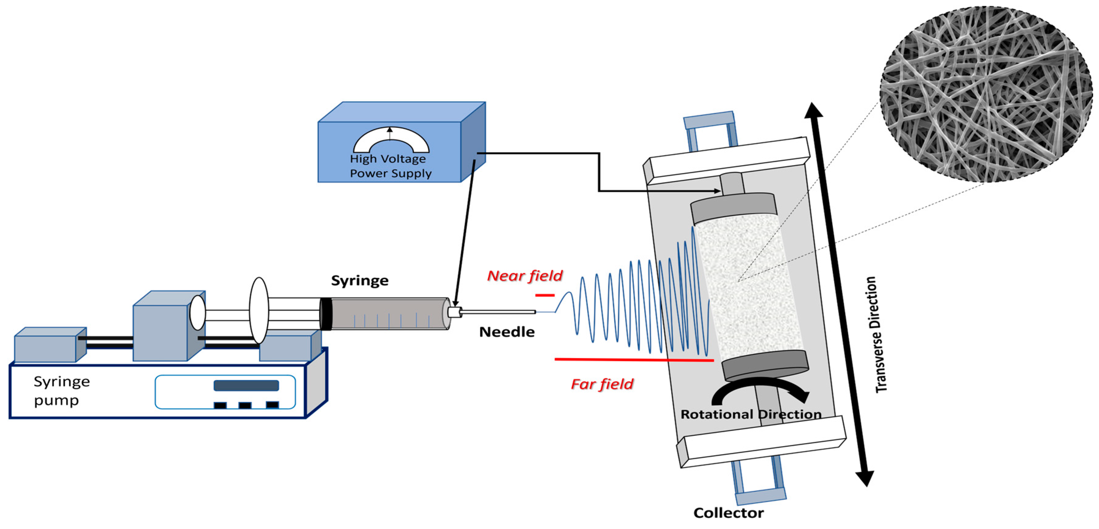
Figure 3.
SEM images of electrospun polyvinyl pyrrolidone (PVP) fibers in aqueous solutions at different concentrations [49]. Reproduced with permission from Higashi et al., Scientific reports; published by Nature, 2020.
Figure 3.
SEM images of electrospun polyvinyl pyrrolidone (PVP) fibers in aqueous solutions at different concentrations [49]. Reproduced with permission from Higashi et al., Scientific reports; published by Nature, 2020.
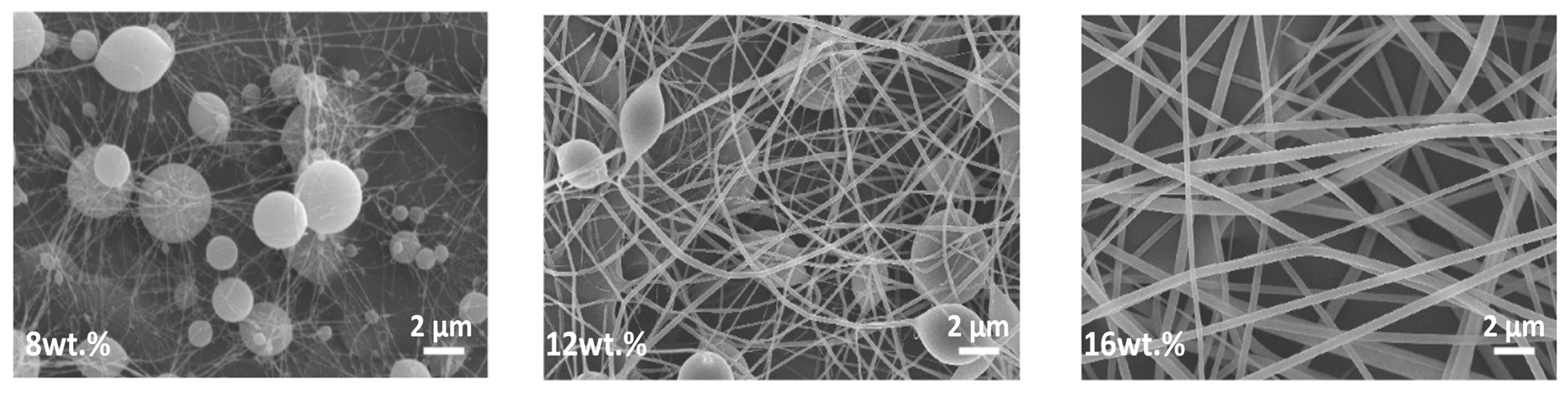
Figure 4.
(a) The overall effect of increasing voltage on the protruding droplet length and number of generated jets, along with their respective field distribution patterns [73]. Reproduced with permission from Liu et al., Nanoscale research letters; published by Springer, 2019. (b) Four jets emerging from a single droplet with a well-defined electrical bending coil [26]. Reproduced with permission from Renker, and Yarin, Polymer; published by Elsevier, 2008.
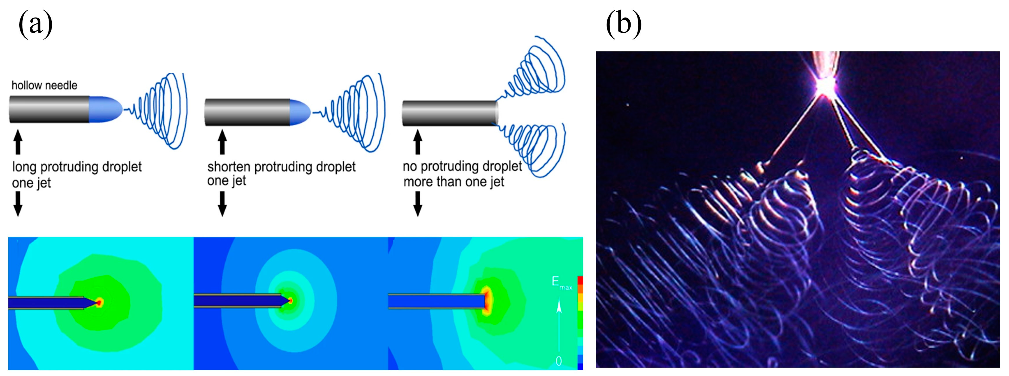
Figure 5.
SEM images of fibers with different morphology: (a) aligned [83]. Reproduced with permission from Mathew et al., Applied Polymer Science; published by Wiley, 2006. (b) core–shell [84]. Reproduced with permission from Sun et al., Advanced Materials; published by Wiley, 2003. (c) hollow [85]. Reproduced with permission from Li et al., Nano letters; published by American Chemical Society, 2004. (d) porous [86]. Reproduced with permission from Rezabeigi et al., Macromolecules; published by American Chemical Society, 2018. (e) multichannel tubular [87]. Reproduced with permission from Zhao et al., Macromolecules; published by American Chemical Society, 2007. (f) nanowire in microtube [88]. Reproduced with permission from Chen et al., Langmuir; published by American Chemical Society, 2010. (g) ribbon-like [89]. Reproduced with permission from Koombhongse et al., Polymer Science Part B: Polymer Physics; published by Wiley, 2001. (h) necklace-like [90]. Reproduced with permission from Jin et al., Langmuir; published by American Chemical Society, 2010. (i) firecracker-shaped [91]. Reproduced with permission from Chang et al., Chemical Communications; published by Royal Society of Chemistry, 2011.
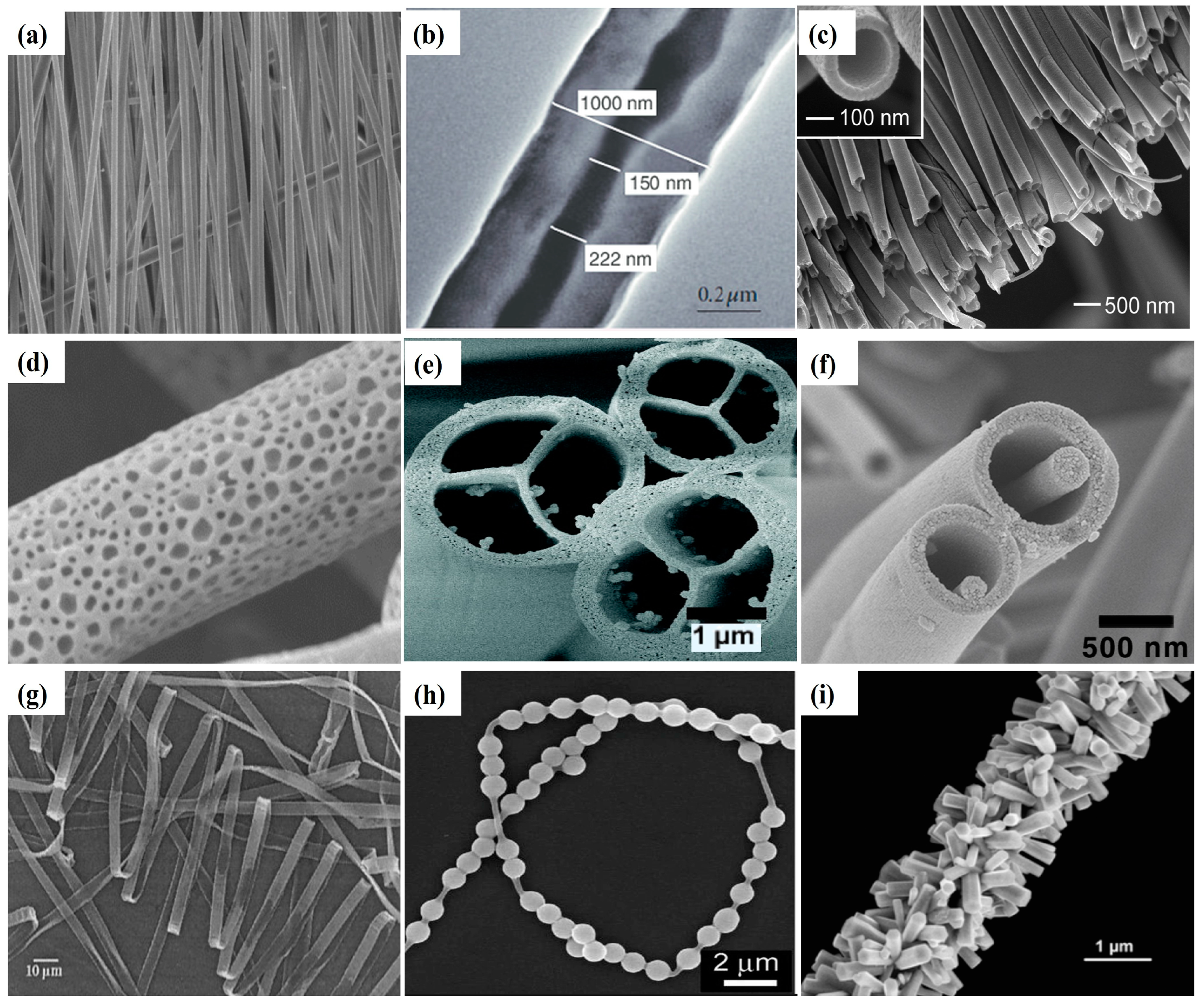
Figure 6.
Schematic representation of different rotating collectors: (a) rotating drum; (b) rotating disc; (c) conical mandrel; (d) rotating rod.
Figure 6.
Schematic representation of different rotating collectors: (a) rotating drum; (b) rotating disc; (c) conical mandrel; (d) rotating rod.
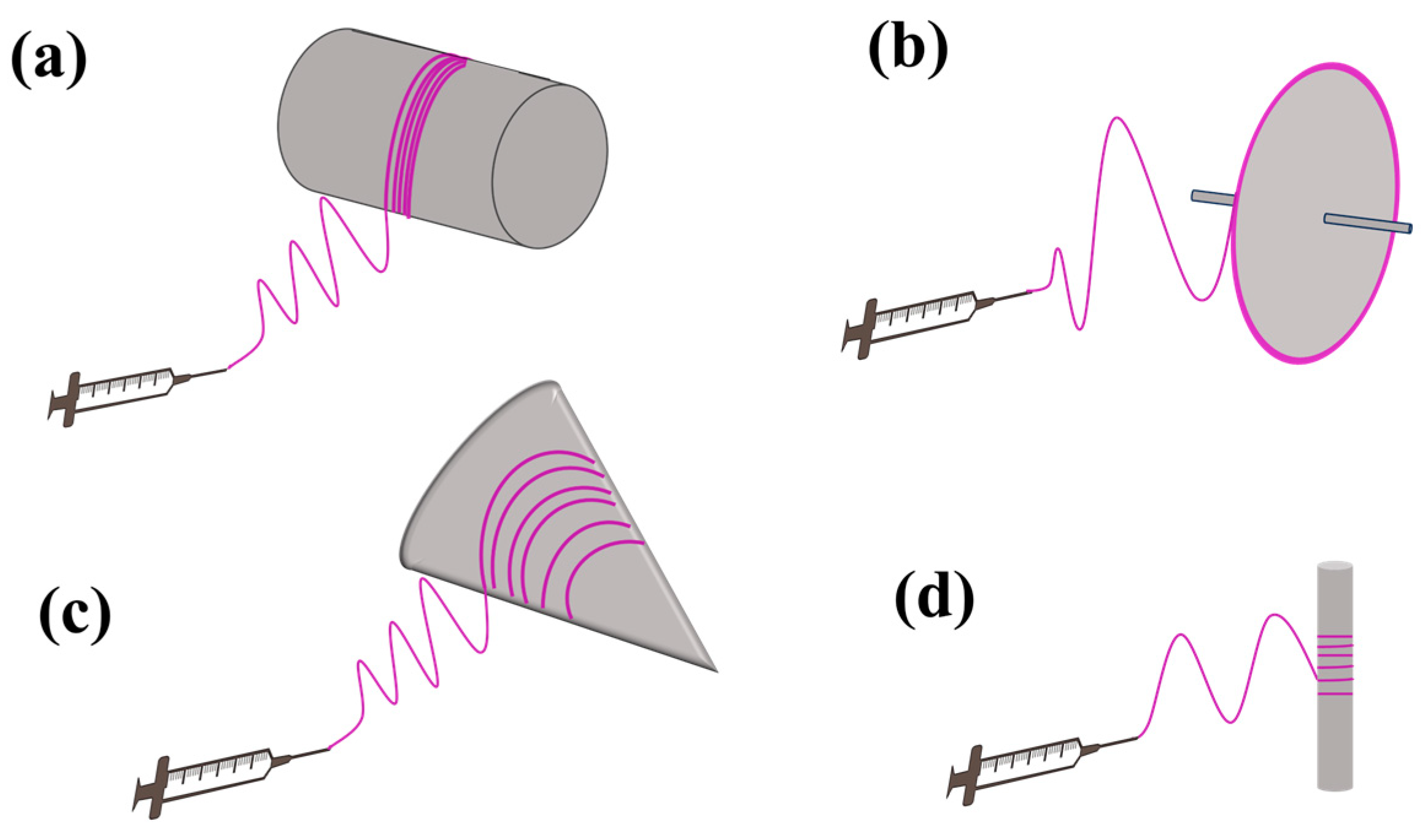
Figure 7.
Schematic representation of different parallel collectors: (a) rotating wire drum and (b) two-pole parallel collector.
Figure 7.
Schematic representation of different parallel collectors: (a) rotating wire drum and (b) two-pole parallel collector.
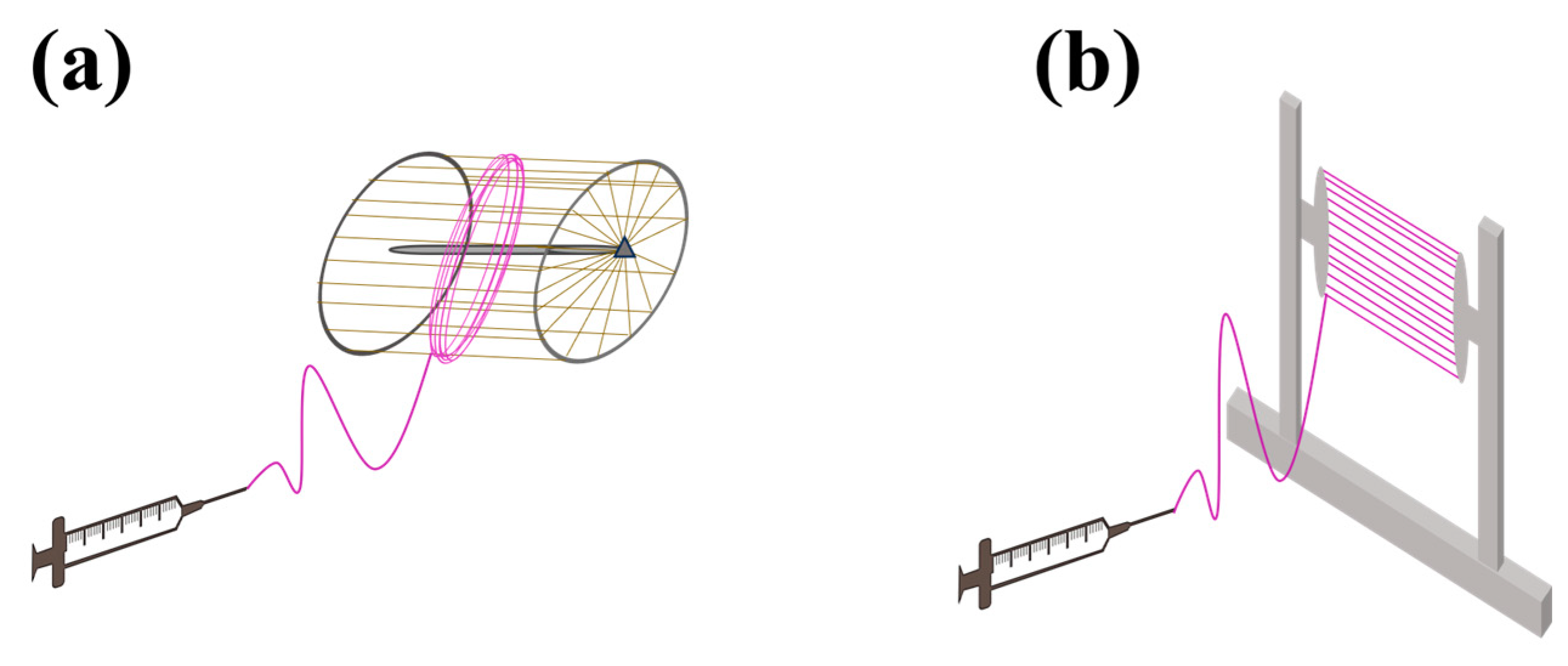

Table 1.
Electrospinning parameters and their effects on fiber morphology.
| Parameters * | Effect | Reference | |
|---|---|---|---|
| Solution parameters | Concentration ↑ | ↑ fiber diameter, beads disappear | [28,29] |
| Viscosity ↑ | ↑ fiber diameter, beads disappear | [30,31] | |
| Molecular weight ↑ | beads disappear | [32,33] | |
| Surface tension ↓ | fiber formation | [34,35] | |
| Conductivity ↑ | ↓ fiber diameter, beads disappear | [36,37] | |
| Process parameters | Voltage ↑ | ↓ fiber diameter | [38,39] |
| Distance between the needle and collector ↑ | ↓ fiber diameter, beads disappear | [38,40] | |
| Flow rate ↑ | ↑ fiber diameter | [38,41] | |
| Ambient parameters | Temperature ↑ | ↓ fiber diameter | [42] |
| Humidity ↑ | Controversial effect on fiber diameter (dependence on polymer hydrophilicity/hydrophobicity) | [43,44] | |
* All parameters increased within optimal range.
Table 2.
Fiber structures and processing configurations: materials, collectors, spinnerets, and applications.
Table 2.
Fiber structures and processing configurations: materials, collectors, spinnerets, and applications.
| Fiber Structure | Materials | Spinneret | Collector | Application | Reference |
|---|---|---|---|---|---|
| Aligned | PLLA | Single needle | Rotating Wire drum | Bone tissue engineering | [92] |
| PLGA | Single needle | Rotating drum | Drug delivery | [93] | |
| PCL/Gelatin | Single needle | Rotating mandrel collector | Skeletal muscle tissue engineering | [94] | |
| PCL | Single needle | Rotating two poles parallel collector | Scaffolds for nerve reconstruction | [95] | |
| PVDF/CNT | Single needle | Rotating drum | Piezoelectric sensor | [96] | |
| PEUU | Single needle | Rotating conical mandrel | Curvilinear scaffolds for heart valve leaflet engineering | [97] | |
| Aligned-to-random | PLGA | Single needle | Parallel electrodes | Gradient scaffold for bone tissue engineering | [98] |
| PCL, PEO, PEG, CA | Single needle | Magnetic collector | Complex gradient materials for tissue engineering | [99] | |
| Core/shell | PU/PS | Coaxial needle | Rotating mandrel | Oil sorbent | [100] |
| PCL/gelatin | Coaxial needle | Grounded collector | Drug delivery | [101] | |
| PEO/PVA/Fe3O4 | Coaxial needle | Grounded collector | Thermal interface management | [102] | |
| Hollow | PVDF-HFP | Coaxial needle | Rotating drum | Polymeric microtubes for water filtration | [103] |
| PCL | Coaxial needle | Grounded collector | Biomedical application | [104] | |
| Porous | PS | Single needle | Grounded collector | Oil sorbent | [105] |
| PEOT/PBT | Single needle | Grounded collector | Drug delivery | [106] |
Disclaimer/Publisher’s Note: The statements, opinions and data contained in all publications are solely those of the individual author(s) and contributor(s) and not of MDPI and/or the editor(s). MDPI and/or the editor(s) disclaim responsibility for any injury to people or property resulting from any ideas, methods, instructions or products referred to in the content. |
© 2024 by the authors. Licensee MDPI, Basel, Switzerland. This article is an open access article distributed under the terms and conditions of the Creative Commons Attribution (CC BY) license (https://creativecommons.org/licenses/by/4.0/).
Share and Cite
MDPI and ACS Style
Ahmadi Bonakdar, M.; Rodrigue, D. Electrospinning: Processes, Structures, and Materials. Macromol 2024, 4, 58-103. https://doi.org/10.3390/macromol4010004
AMA Style
Ahmadi Bonakdar M, Rodrigue D. Electrospinning: Processes, Structures, and Materials. Macromol. 2024; 4(1):58-103. https://doi.org/10.3390/macromol4010004
Chicago/Turabian StyleAhmadi Bonakdar, Mahboubeh, and Denis Rodrigue. 2024. "Electrospinning: Processes, Structures, and Materials" Macromol 4, no. 1: 58-103. https://doi.org/10.3390/macromol4010004