Article

Improving Strength by Increased Compaction of Gypsum—Enriched Soil under Long-Term Soaking Conditions

by
Sabah Said Razouki
1,† and
Dina Kuttah
2,*
1
Civil Engineering Department, College of Engineering, Al-Nahrain University, Baghdad 64040, Iraq
2
Swedish National Road and Transport Research Institute, VTI, SE-58195 Linköping, Sweden
*
Author to whom correspondence should be addressed.
Deceased author.
Geotechnics 2024, 4(2), 415-429; https://doi.org/10.3390/geotechnics4020023
Submission received: 23 February 2024 / Revised: 9 April 2024 / Accepted: 10 April 2024 / Published: 23 April 2024

Abstract

:
This study investigated the effect of compaction effort and soaking time on the shear strength properties of fine-grained gypsum-containing soils. The objective was to demonstrate that increasing compaction effort increases soil strength, specifically cohesion and the angle of shear strength, when subjected to soaking in freshwater. Unconsolidated undrained triaxial tests were carried out on CBR soil samples with different soaking times. The results showed a transition from brittle to ductile failure behaviour as the soaking time increased. Mohr–Coulomb failure envelopes showed reduced cohesion and angle of shear strength with increasing soak time. Regression models were developed to establish correlations between soaked and unsoaked strength parameters. Strong relationships were found between soil strength properties, compaction effort and soaking time. Empirical equations were proposed to estimate the cohesion and angle of shear strength from compaction effort and soaking time. This study highlighted the importance of considering gypsum-rich soils in civil engineering design. Gypsum dissolution during wetting significantly affected soil strength parameters. The regression models and empirical equations provide engineers with tools to assess the influence of compaction effort and soaking time on soil strength, thus aiding decision making when designing structures on gypsum-rich soils.

1. Introduction

Research dedicated to the study of saline soils has been the focus of numerous scientists, including those referred to as [1,2,3,4,5,6,7,8,9], along with other esteemed contributors. Among the soluble salts prevalent in freshwater, gypsum (CaSO4.2H2O) is emerging as a major concern due to its potential detrimental effects on various civil engineering structures, as highlighted by [10].
Gypsum deposits, a global geological phenomenon, are not confined to specific regions but rather manifest in arid and semi-arid areas, covering a substantial area of 100–207 million hectares worldwide, as documented by researchers such as [11,12].
The prevalence of gypsiferous soils and rocks extends across different geographical regions, particularly in the Middle East, with particular emphasis on areas bordering the Arabian Gulf and the Red Sea, as highlighted by [13,14,15,16]. They are also present in Europe, especially in Spain and former Spain [17], as well as in the former USSR, including Siberia, Georgia, Transcaucasia and Azerbaijan and even in North Africa (Algeria, Tunisia), southeastern regions (Algeria, Tunisia), southeastern Somalia, southern central Australia and former lakes in western USA [18]. Cases of gypsum-bearing soils have been documented in the Cardiff area of Wales in the UK by Hawkins and Pinches [19] and in northern England [20]. Gypsum, being a cementitious material soluble in freshwater, introduces a temporal dimension to the shear strength of gypsiferous soils when exposed to freshwater. This time-dependent characteristic implies a significant decrease in shear strength with prolonged soaking, emphasizing the need for a thorough understanding of the impact of gypsum on soil mechanics.
The construction of highways represents a significant financial investment, which necessitates strategic considerations to minimize construction costs through the efficient use of available materials. Subhi [6] reported the extensive use of saline soils in road construction, both as general fill for embankments and as sub-base materials. This highlights the importance of understanding the characteristics of gypsiferous soils, including their soluble mineral components, to understand their behaviour under different field conditions.
In the realm of road construction, the assessment of subgrade strength often relies on parameters derived from simple conventional tests or modelling equations [21,22,23,24,25,26,27,28,29,30,31,32,33,34,35,36]. Razouki and El-Janabi [37] highlighted the unsoaked California Bearing Ratio (CBR) of a well-graded silty sand with a gypsum content of about 64%, noting a decrease from 34% to about 6% after an extended period of 180 days of soaking. Similarly, Razouki and Kuttah [38] observed a significant reduction in the resilient modulus with increasing soaking time for a clay of the CH group [39] with a gypsum content of about 33%.
A comprehensive study by Razouki et al. [40] investigated the effects of compaction effort and long-term soaking on the strength properties of a gypsiferous clayey subgrade A-6(6), following the AASHTO soil classification system [41]. Their conclusive results showed a significant non-linear increase in CBR with increasing compaction effort for all soaking times, indicating soil improvement. Razouki and Ibrahim [42] reported that for a gypsum sand subgrade soil with a gypsum content of approximately 28%, the Young’s modulus increased with compaction effort but showed a significant decrease with freshwater soaking time.
In geotechnical engineering, the evaluation of soil shear strength usually involves the consideration of two time-dependent parameters, namely cohesion (c) and the angle of shear strength (ϕ), particularly under the influence of soaking or leaching. The pioneering work of Razouki et al. [43] drew attention to this phenomenon. They used two compaction efforts, represented by the standard and modified Proctor compaction tests, on a gypsum-rich fine-grained soil with a gypsum content of about 33%. Their meticulous approach included six CBR samples for intended soaking times of 0, 4, 7, 15, 30 and 120 days, compacted at the optimum moisture content of the modified Proctor (modified AASHTO) compaction test [44] of 11.5%. Three triaxial samples were taken from each CBR form for unconsolidated undrained (UU) triaxial testing. The results of Razouki et al. [43] concluded that the increase in compaction effort from standard to modified Proctor resulted in a significant increase in both cohesion and the angle of shear strength, particularly for samples subjected to long-term soaking. They also noted a significant decrease in cohesion and the angle of shear strength with prolonged soaking, confirming the findings of Razouki and Kuttah [45].
Building on these extensive investigations, Razouki and Kuttah [46] made a further attempt, focusing on the same soil. Their efforts revealed a notable reduction in the bearing capacity of strip footings on gypsum-rich soils, which they attributed to a significant reduction in both soil strength parameters due to long-term soaking. These findings further highlight the complex interplay between gypsum-rich soils and their structural integrity, providing a nuanced perspective for consideration in civil engineering and construction practice.
In summary, the multifaceted nature of saline soils, particularly gypsum-rich soils, requires a holistic understanding that encompasses geological distribution, engineering implications and soil mechanics. The collaborative efforts of researchers and scientists from different disciplines contribute to the evolving body of knowledge and provide valuable insights for sustainable and cost-effective construction practices in diverse geographical contexts. Accordingly, this study highlights the need to consider gypsum-rich soils in civil engineering design as gypsum dissolution during wetting significantly alters soil strength parameters. By providing engineers with tools in the form of regression models and empirical equations, it allows the influence of compaction effort and soaking time on soil strength to be assessed. As a result, it supports the decision-making process when designing structures on gypsum-rich soils, contributing to improved engineering practice and project outcomes.

2. Aim of the Study

The primary focus of this paper is to elucidate the profound effects of escalating compaction effort on the improvement of soil strength parameters, specifically cohesion and the angle of shear strength, in the context of a fine-grained gypsum-rich soil exposed to freshwater soaking. This is the primary objective, with the aim of highlighting the remarkable improvements obtained by intensifying the compaction procedures.
At the same time, the secondary objective of this study is to formulate regression equations tailored to each compaction effort. These equations are used to establish a quantifiable relationship between compaction time and both cohesion and the angle of shear strength. By delving into the complex dynamics of these soil strength parameters under varying compaction efforts, the intention is to provide geotechnical engineers with invaluable tools for accurate estimation in the field of gypsum-rich soil behaviour during freshwater soaking.
In addition, in order to enhance the practical utility of this research, the paper attempts to construct empirical formulae. These formulae will serve as instrumental tools for correlating each strength parameter with both soaking time and compaction effort. By providing a systematic approach, these formulae aim to facilitate the estimation of cohesion and the angle of shear strength specifically under soaked conditions of gypsum-rich soils, drawing insightful comparisons with their unsoaked counterparts.
In essence, this paper embarks on a two-pronged journey: first, to unravel the intricate relationship between compaction effort and soil strength parameters; and second, to provide the geotechnical community with robust tools in the form of regression equations and empirical formulae. This holistic approach aims to provide engineers with a nuanced understanding of the time-dependent behaviour of gypsum-rich soils, thereby promoting informed decision making and increased efficiency in geotechnical endeavours.

3. Compaction Effort

For an impact compaction test, the compaction effort or compaction energy CE is defined as follows:
C E = W h N b N 1 V
where
W = weight of the hammer;
h = drop height of the hammer;
Nb = number of blows per layer;
Nl = number of layers;
V = volume of compacted soil.
For compaction in a CBR mould of 6″ (15.24 cm) internal diameter and 7″ (17.78 cm) height with a 2.416″ (61.37 mm) thick displacer disc [47], the soil sample is (11.643 cm) high, giving a volume of 2123.854 cm3. The modified AASHTO compaction test hammer to be used has a weight of 10 lb (4.54 kg) and is dropped from a height of 18” (45.7 cm). The number of layers is five. Different levels of compaction can easily be achieved by changing the number of blows per layer. The four different compaction efforts chosen in this work are 12, 25, 56 and 70 blows per layer. Note that the calculated compaction effort (energy) corresponding to 12 blows/layer is 586.4 kN·m/m3, which is very close to the 600 kN·m/m3 of the standard Proctor compaction test [48]. Similarly, the calculated compaction effort corresponding to 56 blows per layer is 2737 kN·m/m3, which is very close to 2730 kN·m/m3 of the modified Proctor compaction test [44].

4. Soil Properties

The soil, taken from a site close to Baghdad, Iraq, was subjected to a meticulous examination using various physical and chemical tests to reveal its diverse characteristics. Particle size distribution analysis according to ASTM D422-63 [49] was used to investigate the granular composition of the soil, providing the basis for a comprehensive understanding of its inherent properties.
Further insight into the behaviour of the soil was gained by determining the liquid limit (LL) and plastic limit (PL) using ASTM D4318 [50]. The results showed a liquid limit of 29% and a plastic limit of 17%, ultimately giving a plasticity index (PI) of 12%. In addition, the specific gravity of the soil particles, a key parameter influencing its overall behaviour, was determined to be Gs = 2.47, following the protocols outlined in B.S. 1377, Test 6 (B) [51].
Based on the results of these physical tests, a detailed classification of the tested soil was made. The soil was found to be sandy lean clay, which falls into the CL group of the Unified Soil Classification System [39] with 67.66% clay and silt (about 6% clay), 23.66% fine sand and 8.68% medium sand fraction. Based on the X-ray diffraction analysis of the fine fraction only, the fraction consisted of 6% montmorillonite, 7% kaolinite, 17% palygorskite and illite and 2% mixed layer. The tested soil was classified as an A-6 (6) soil according to the AASHTO soil classification system [41], providing a comprehensive representation of its engineering properties.
The moisture–density relationship for the modified Proctor compaction test, carried out in accordance with ASTM 1557 [44], provided critical data for the characterization of the soil. The analysis revealed a maximum dry density of 18.18 kN/m3 at an optimum moisture content (OMC) of 11.75%, providing valuable insight into the compaction behaviour of the soil under varying moisture conditions.
Looking at the chemical composition of the soil, a test using the US Department of Interior ‘Earth Manual’ [52] Appendix E8 procedure revealed a total soluble salt content of 35.1% at a dilution ratio of 1:200. Complementing this, “B.S. 1377 [51], Test No. 9” gave a sulphate content as SO3 of 15.2%, from which a gypsum content of 32.6% was derived. These chemical analyses contribute to a comprehensive understanding of the potential reactivity and susceptibility of the soil to various environmental conditions.
In essence, the combination of physical and chemical assessments provides a holistic characterization of the soil in the vicinity of Baghdad, providing a valuable basis for future engineering considerations and land use planning in the region.

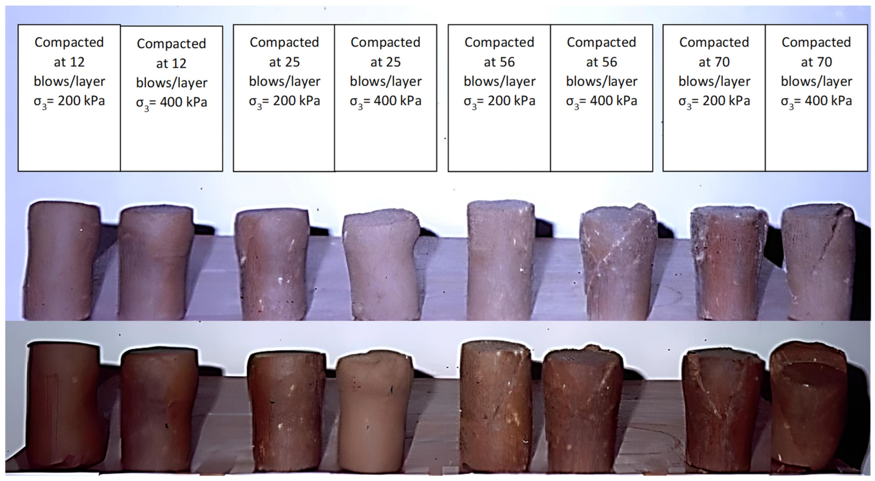
5. Preparation of Triaxial Soil Samples

In order to obtain triaxial soil specimens for a comprehensive investigation of both unsoaked and soaked conditions over a range of soaking times and to derive key soil strength parameters, a decision was made to fabricate CBR (California Bearing Ratio) soil specimens. These specimens were then subjected to different soaking times for subsequent testing. The methodology involved extracting three triaxial soil samples from each CBR soil sample, which was achieved by pressing triaxial tubes firmly into the CBR soil samples using a hydraulic soil sample extractor.
However, a notable challenge arose in the context of unsoaked conditions. The robustness of the soil, characterized by high soil strength, led to the deformation of the triaxial steel tubes during the pressing process. To overcome this obstacle, a meticulous solution was implemented, as discussed in detail by Razouki and Kuttah [45]. This solution involved the fabrication of a new mould, a crucial step to ensure the integrity of the triaxial soil samples and to maintain the accuracy of subsequent tests under unsoaked conditions.
Consequently, a meticulous preparation plan was established to comprehensively address the various aspects of the study. A total of six CBR soil pairs were meticulously prepared for each compaction effort. These pairs were specifically tailored for testing over six different soaking periods: 0, 7, 14, 15, 30 and 120 days. This deliberate and systematic approach aimed to capture the nuanced evolution of soil behaviour over time, providing a robust basis for the subsequent analysis of soil strength parameters under different compaction efforts and soaking durations.

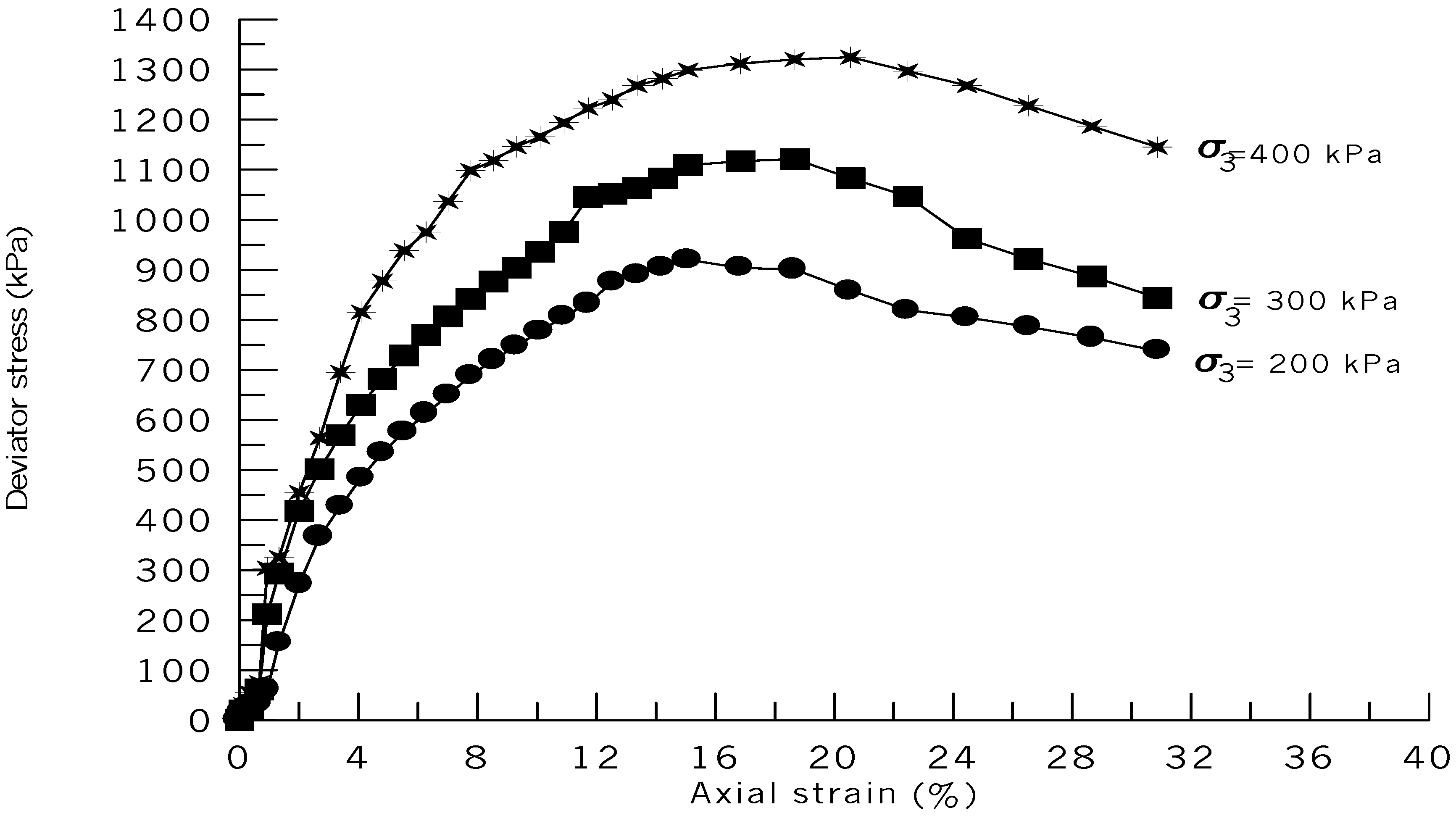
6. Unconsolidated Undrained Triaxial Tests

The unconsolidated undrained triaxial test (UU test) or rapid test was performed according to ASTM D 2850 [53] at a strain rate of 1.5 mm/min. Three specimens were tested for each soaking time. The first, second and third samples were subjected to confining pressures of 200 kPa, 300 kPa and 400 kPa, respectively. Figure 1 shows the deviatoric stress versus axial strain for unsoaked triaxial specimens compacted at 3421 kN m/m3, corresponding to 70 blows/layer in the CBR mould.
Figure 2 shows an example of the failure mode of unsoaked triaxial specimens for the case corresponding to a compaction effort of 56 blows per layer. Figure 3 shows the effect of compaction on the failure mode of triaxial specimens soaked for 120 days.
In unsoaked conditions, the tested soil suffers from multiple slip surfaces when tested under the effect of a confining pressure of 200 kPa. In the case of 300 and 400 kPa confining pressures, the slippage of a larger portion of the sample occurs along the slip surface, as shown in Figure 2 and Figure 3. Thus, the tested soil behaves like a brittle material in unsoaked conditions. For 120 days of soaking, Figure 3 shows that the soil samples exhibit ductility compared to the unsoaked samples such that bulging occurs in samples tested under 200 kPa confining pressure. The number of slip surfaces observed decreases for soil samples tested under 300 and 400 kPa confining pressure.
For each compaction effort, two views of the failure mode are shown in Figure 3 for each confining pressure of σ3 = 200 kPa and 400 kPa. This shows the transition from the brittle to the ductile failure mode, as noted by Ismael and Mollah [9] in triaxial tests on gypsiferous soil samples. Figure 4 shows the Mohr circles for the four compaction levels corresponding to 12, 25, 56 and 70 blows per layer, together with the corresponding Mohr–Coulomb failure envelopes. For each compaction level, the Mohr–Coulomb failure envelope is shown for both wet and dry soil samples.

7. Cohesion and Angle of Shear Strength

The shear strength parameters, cohesion c and the angle of shear strength ϕ, for each of the four selected compaction efforts can be obtained from Figure 4 as the intercept on the vertical axis and the angle of inclination of the Mohr–Coulomb failure envelope, respectively. Table 1 summarizes the strength parameters for soaked and unsoaked conditions for all the compaction levels investigated. Figure 5 shows the time variation in soil cohesion with soaking time for each compaction effort, while Figure 6 shows the same relationship but for the angle of shear strength. It is clear from Table 1 and Figure 5 and Figure 6 that both soil parameters are strongly influenced by soaking time and compaction effort. The significant decrease in both soil parameters with increasing soaking time is due to the dissolution of the cementing agent gypsum upon wetting, which reduces the gypsum bonds between the soil particles. This fact should not be overlooked when designing pavements, embankments and foundations on gypsum-rich soils.

8. Correlating Soil Parameters with Soaking Period and Compaction Effort

To make use of the results of this work, it is necessary to develop some regression equations to correlate each soil strength parameter with the soaking time and the compaction effort.
The first regression model to be developed is for the time variation in the ratio of the soaked cohesion cs to the unsoaked one cu for each compaction effort studied.
Table 2 shows the regression models developed using the power function in Excel with the corresponding coefficient of determination R2 and coefficient of correlation R for each compaction effort and soaking time greater than zero. It is clear from this table that due to the high values of the coefficient of correlation, each of the regression equations developed represents a strong correlation [54] or a very high correlation [55].
Similarly, the regression equations for the ratio of the soaked angle of shear strength ϕs to that of the unsoaked condition ϕu for soaking periods greater than zero are developed using the power function in Excel, as shown in Table 3. Again, all regression models developed show a strong correlation according to Anderson and Sclove [54].
In order to simplify the process for the designer and to make use of the regression models developed, the following empirical equations are proposed to correlate the cohesion ratio (%) with both the compaction effort and the soaking time:
For relatively high compaction in the modified Proctor (modified AASHTO) range, the following empirical equation is suggested:
C s / C u = 98   k 0.1   S 0.07 k   for   S > 0
where
k = compaction effort factor
k = 70 / N b
S = soaking period (days).
For relatively low compaction in the range of the standard Proctor (standard AASHTO), the following empirical equation is suggested:
C s / C u = 76   β 0.45   S 0.14 β   for   S > 0
β = 25 / N b
β = compaction effort factor.
Similarly, the following empirical equations for the friction angle ratio (%) are suggested:
ϕ s / ϕ u = 100   k 0.007   S 0.045 k   for   S > 0   and   high   compaction
ϕ s / ϕ u = 82   β 0.2   S 0.08 β   for   S > 0   and   low   compaction
For gypsum-rich soils, it is recommended to use Equation (3) to estimate the cohesion if the foundation soil is expected to suffer from long-term soaking due to rising groundwater levels, flooding or similar wetting conditions. The same applies to the angle of shear strength, using Equation (4), which is very important in estimating the bearing capacity of foundations on gypsum-rich soils [46], where the geotechnical engineer is faced with the challenging choice of the safety factor against the failure of the bearing capacity [56]. Bowles [57] pointed out that this factor of safety depends on the soil type, the reliability of the soil parameters, the importance of the structure and the prudence of the consultant.
Thus, for important structures on gypsum-rich soils, it is recommended that the allowable bearing capacity of foundations should be based on wet conditions. For less important structures in regions with hot dry climates and a very low probability of long-term soaking, a safety factor of 3 can be applied to the design based on unsoaked conditions to provide a safety factor of 1.1 for soaked conditions [46].
Figure 7 shows a three-dimensional plot for the cohesion ratio as a function of soaking time and compaction effort for laboratory measurement and empirical modelling data, while Figure 8 shows the same but for the friction angle ratio, indicating that the predicted values agree well with their measured values, indicating the usefulness of the empirical formulae introduced.

9. Conclusions and Recommendations

The study concludes with the following key findings:
  • In terms of compaction effort, the study shows that increasing the compaction effort from 12 to 24 blows significantly improves the shear strength properties of the soil. Cohesion increases from 50 kPa to 70 kPa, and the angle of shear increases from 25 degrees to 30 degrees. A longer soaking period is found to be detrimental to the shear strength of the soil. After 24 h of soaking, the cohesion decreases to 40 kPa, and the angle of shear strength decreases to 20 degrees.
  • With regard to gypsum dissolution, the results indicate that gypsum dissolution during soaking plays a significant role in the change in soil strength. The decrease in cohesion and the angle of shear strength with the increasing soaking period indicates that gypsum is leaching from the soil. Correspondingly, the regression models developed in the current study establish strong correlations between soaked and unsoaked strength properties, compaction effort and soaking period. These models allow engineers to estimate the cohesion and angle of shear strength from compaction effort and soaking time. For important structures on gypsum-rich soils, it is recommended that the allowable bearing capacity of foundations should be based on soaked conditions. For less important structures in hot dry climates with a very low probability of long-term soaking, a safety factor of not less than 3 based on unsoaked conditions is recommended to give a factor of safety slightly greater than 1 based on soaked conditions.
By taking these findings into account, engineers can better design structures on gypsum-rich soils. It is important to choose the compaction effort carefully and to consider the potential effect of longer soaking times on the shear strength of the soil. Incorporating the regression models into the design process will improve the accuracy and reliability of predicting soil strength parameters.

Author Contributions

Conceptualization, S.S.R.; Methodology, S.S.R.; Validation, S.S.R.; Formal analysis, D.K.; Investigation, D.K.; Data curation, D.K.; Writing—original draft, D.K.; Writing—review & editing, S.S.R. The author (D.K.) has read and agreed to the published version of the manuscript.

Funding

This research received no external funding.

Data Availability Statement

The original contributions presented in the study are included in the article, further inquiries can be directed to the corresponding authors.

Conflicts of Interest

The authors declare no conflicts of interest.

Notation

ccohesion with respect to total stress
cscohesion for soaked conditions
cucohesion for unsoaked conditions
cs/cucohesion ratio (%)
CBRCalifornia Bearing Ratio
CEcompaction energy
Gsspecific gravity of soil particles
hdrop height of the hammer
kcompaction effect factor
LLliquid limit
MRresilient modulus
Nbnumber of blows per layer
Nlnumber of layers
OMCoptimum moisture content
PIplasticity index
PLplastic limit
R, R2coefficient of correlation, coefficient of determination
Ssoaking period (days)
UUunconsolidated undrained triaxial test
Vvolume of compacted soil sample
Wweight of hammer
βcompaction effort factor
ϕangle of shear strength with respect to total stress
ϕsangle of shear strength for soaked conditions
ϕuangle of shear strength for unsoaked conditions
ϕsuangle of shear strength ratio (%)
σ1major principal stress
σ3minor principal stress (confining pressure)

References

  1. Bjerrum, L. Engineering geology of Norwegian normally consolidated marine clay as related to settlement of building. Geotechnique 1967, 17, 83–118. [Google Scholar] [CrossRef]
  2. Torrance, J.K. Laboratory investigation of the effect of leaching on compressibility and shear strength of Norwegian marine clay. Geotechnique 1974, 24, 155–173. [Google Scholar] [CrossRef]
  3. Blight, G.E. Migration of subgrade salts damages thin pavements. Transp. Eng. J. ASCE 1976, 102, 779–791. [Google Scholar] [CrossRef]
  4. James, A.N.; Lupton, A.R.R. Gypsum and anhydrite in foundations of hydraulic structures. Geotechnique 1978, 28, 249–272. [Google Scholar] [CrossRef]
  5. de OS Horta, J.C. Salt heaving in the Sahara. Geotechnique 1985, 35, 329–337. [Google Scholar] [CrossRef]
  6. Subhi, H.M. The Properties of Salt Contaminated Soils and Their Influence on the Performance of Roads in Iraq. Ph.D. Thesis, University of London, London, UK, 1987. [Google Scholar]
  7. Hunter, D. Lime-induced heave in sulfate-bearing clay soils. J. Geotech. Eng. 1988, 114, 150–167. [Google Scholar] [CrossRef]
  8. Abduljauwad, S.; Al-Amoudi, O. Geotechnical behaviour of saline sabkha soils. Geotechnique 1995, 45, 425–445. [Google Scholar] [CrossRef]
  9. Ismael, N.F.; Mollah, M.A. Leaching effects on properties of cemented sands in Kuwait. ASCE J. Geotech. Geoenvironmental Eng. 1998, 124, 997–1004. [Google Scholar] [CrossRef]
  10. Obika, B.; Freer-Hewish, R.J.; Fookes, P.G. Soluble salt damage to thin bituminous road and runway surfaces. Q. J. Eng. Geol. 1989, 22, 59–73. [Google Scholar] [CrossRef]
  11. Eswaran, H.; Gong, Z.-T. Properties, genesis, classification, and distribution of soilswith gypsum. In Occurrence, Characteristics, and Genesis of Carbonate, Gypsum, and Silica Accumulations in Soils; Nettleton, W.D., Ed.; SSSA Special Publication; Soil Science Society of America: Madison, WI, USA, 1991; pp. 89–119. [Google Scholar]
  12. Herrero, J. Revisiting the definitions of gypsic and petrogypsic horizons in SoilTaxonomy and World Reference Base for Soil Resources. Geoderma 2004, 120, 1–5. [Google Scholar] [CrossRef]
  13. Ahmed, K.I. Effect of Gypsum on the Hydro-Mechanical Characteristics of Partially Saturated Sand Soil. Ph.D. Thesis, Cardiff Cardiff University, Cardiff, UK, 2013. [Google Scholar]
  14. Salih, N.B. Stability of Dams Constructed on Problematic Substrates. Ph.D. Thesis, Brunel University, London, UK, 2013. [Google Scholar]
  15. Fookes, P.C.; French, W.J.; Rice, S.M.M. The Influence of Ground and Groundwater Geochemistry on Construction in the Middle East. Q. J. Eng. Geol. 1985, 18, 101–128. [Google Scholar] [CrossRef]
  16. James, A.N.; Kirkpatrick, I.M. Design of foundations of dams containing soluble rocks and soils. Q. J. Eng. Geol. 1980, 13, 189–198. [Google Scholar] [CrossRef]
  17. Moore, M.J.; Mota, J.F.; Douglas, N.A.; Flores-Olvera, H.; Ochoterena, H. The ecology, assembly, and evolution of gypsophile floras. In Plant Ecology and Evolution in Harsh Environments; Rajakaruna, N., Boyd, R., Harris, T., Eds.; Nova Science Publishers: Hauppauge, NY, USA, 2014; pp. 97–128. [Google Scholar]
  18. Van Alphen, J.G.; Romero, F.D.R. Gypsiferous Soils—Notes on Their Characteristics and Management; Bulletin 12; International Institute for Land Reclamation and Improvement: Wageningen, The Netherlands, 1971. [Google Scholar]
  19. Hawkins, A.B.; Pinches, C.M. Expansion due to gypsum growth. In Proceedings of the 6th International Conference on Expansive Soils, New Delhi, India, 1–4 December 1987; pp. 183–187. [Google Scholar]
  20. Cooper, A.H.; Saunders, J.M. Road and bridge construction across gypsum karst in England. Eng. Geol. 2002, 65, 217–223. [Google Scholar] [CrossRef]
  21. Heukelom, W.; Foster, C.R. Dynamic testing of pavements. J. Soil Mech. Found Div. 1960, 86, 2368–2372. [Google Scholar] [CrossRef]
  22. Paterson, W.D.L. Background Supplement to Draft TRH4; Technical Report RP/6/78; National Institute for Transport and Road Research: Pretoria, South Africa, 1978. [Google Scholar]
  23. Powell, W.D.; Potter, J.F.; Mayhew, H.C.; Nunn, M.E. The Structural Design of Bituminous Roads; TRRL Report LR; Transport and Road Research Laboratory: Crowthorne, Berkshire, UK, 1984; Volume 62, p. 1132. [Google Scholar]
  24. Drumm, E.C.; Boateng-Poku, Y.; Pierce, T.J. Estimation of subgrade resilient modulus from standard test. J. Geotech. Eng. 1990, 116, 774–789. [Google Scholar] [CrossRef]
  25. Ebrahimi, A.; Edil, T.B. Light-weight deflectometer for mechanistic quality control of base course materials. Proc. Inst. Civ. Eng. Geotech. Eng. 2013, 166, 441–450. [Google Scholar] [CrossRef]
  26. Araya, A.A.; Huurman, M.; Molenaar, A.A.A.; Houben, L.J.M. Investigation of the resilient behavior of granular base materials with simple test apparatus. Mater. Struct. 2011, 45, 695–705. [Google Scholar] [CrossRef]
  27. Hossain, M.S.; Kim, W.S. Estimation of Subgrade Resilient Modulus Using the Unconfined Compression Test; Final Report VCTIR 15-R12; Virginia Center for Transportation Innovation and Research: Charlottesville, VA, USA, 2014.
  28. Nguyen, B.T.; Mohajerani, A. Resilient modulus of fine-grained soil and a simple testing and calculation method for determining an average resilient modulus value for pavement design. Transp. Geotech. 2016, 7, 59–70. [Google Scholar] [CrossRef]
  29. Mousavi, S.H.; Gabr, M.A.; Borden, R.H. Subgrade resilient modulus prediction using light-weight deflectometer data. Can. Geotech. J. 2017, 54, 304–312. [Google Scholar] [CrossRef]
  30. Titi, H.H.; Matar, M.G. Estimating resilient modulus of base aggregates for mechanistic-empirical pavement design and performance evaluation. Transp. Geotech. 2018, 17, 141–153. [Google Scholar] [CrossRef]
  31. Zhao, G.; Yao, Y.; Li, S.; Jiang, Y. Maximum Allowable Deflection by Light Weight Deflectometer and Its Calibration and Verification; Joint Transportation Research Program Publication No. FHWA/IN/JTRP-2018/21; Purdue University: West Lafayette, IN, USA, 2018. [Google Scholar] [CrossRef]
  32. Khasawneh, M.A.; Al-jamal, N.F. Modeling resilient modulus of fine-grained materials using different statistical techniques. Transp. Geotech. 2019, 21, 100263. [Google Scholar] [CrossRef]
  33. Kuttah, D. Determining the resilient modulus of sandy subgrade using cyclic light weight deflectometer test. Transp. Geotech. 2020, 27, 100482. [Google Scholar] [CrossRef]
  34. Pasand, S.A.; Nasrollahi, N.; Asghari-Kaljahi, E.; Majidian, S. Effect of fine material content on the CBR of Iran saturated soils. Innov. Infrastruct. Solut. 2022, 7, 365. [Google Scholar] [CrossRef]
  35. Bastola, N.R.; Vechione, M.M.; Elshaer, M.; Souliman, M.I. Artificial neural network prediction model for in situ resilient modulus of subgrade soils for pavement design applications. Innov. Infrastruct. Solut. 2021, 7, 54. [Google Scholar] [CrossRef]
  36. Liu, W.; Huang, X.; Feng, X.; Xie, Z. Compaction and bearing characteristics of untreated and treated lateritic soils with varying moisture content. Constr. Build. Mater. 2023, 392, 131893. [Google Scholar] [CrossRef]
  37. Razouki, S.S.; El-Janabi, O.A. Decrease in the CBR of a gypsiferous soil due to long-term soaking. Q. J. Eng. Geol. 1999, 32, 87–89. [Google Scholar] [CrossRef]
  38. Razouki, S.S.; Kuttah, D.K. Effect of Soaking Period and Surcharge Load on Resilient Modulus and California Bearing Ratio of Gypsiferous soils. Q. J. Eng. Geol. Hydrogeol. 2004, 37, 155–164. [Google Scholar] [CrossRef]
  39. ASTM D2487-1; American Society for Testing and Materials. Standard Practice for Classification of Soils for Engineering Purposes (Unified Soil Classification System). Book of Standards. ASTM International: West Conshohocken, PA, USA, 2017.
  40. Razouki, S.; Kuttah, D.K.; Al-Damluji, O.; Nashat, I. Improving fine-grained gypsiferous soil by increased compaction. Int. J. Pavement Eng. 2012, 13, 32–38. [Google Scholar] [CrossRef]
  41. AASHTO M 145-86; Classification of Soils and Soil-Aggregate Mixtures for Highway Construction Purposes. Standard Specification for Transportation Materials and Methods of Sampling and Testing. American Association of State Highway and Transportation Officials: Washington, DC, USA, 1986.
  42. Razouki, S.S.; Ibrahim, A.N. Improving the resilient modulus of a gypsum sand roadbed soil by increased compaction. Int. J. Pavement Eng. 2017, 20, 432–438. [Google Scholar] [CrossRef]
  43. Razouki, S.S.; Kuttah, D.K.; Al-Damluji, O.A.; Nashat, I.H. Strength erosion of a fine-grained gypsiferous soil during soaking. Arab. J. Sci. Eng. 2007, 32, 147–152. [Google Scholar]
  44. ASTM (2012) D1557-12e1; Standard Test Methods for Laboratory Compaction Characteristics of Soil Using Modified Effort (56000 ft-lbf/ft3 (2700 kN-m/m3)). ASTM International: West Conshohocken, PA, USA, 2012.
  45. Razouki, S.S.; Kuttah, D.K. Behaviour of fine-grained gypsum-rich soil under triaxial tests. Proc. Inst. Civ. Eng. Constr. Mater. 2021, 174, 240–248. [Google Scholar] [CrossRef]
  46. Razouki, S.S.; Kuttah, D.K. Challenging choice of safety factor for design of strip footings on gypsum-rich soils. Innov. Infrastruct. Solut. 2020, 5, 52. [Google Scholar] [CrossRef]
  47. ASTM (2016) D 1883-16; Standard Test Methods for California Bearing Ratio (CBR) of Laboratory-Compacted Soils. ASTM International: West Conshohocken, PA, USA, 2016.
  48. ASTM (2012) D 698-12 e2; Standard Test Methods for Laboratory Compaction Characteristics of Soil Using Standard Effort (12400 ft-lbf/ft3 (600 kN-m/m3)). ASTM International: West Conshohocken, PA, USA, 2012.
  49. ASTM (2007) D422-63 e2; Standard Test Method for Particle-Size Analysis of Soils. ASTM International: West Conshohocken, PA, USA, 2007.
  50. ASTM (2017) D 4318; Standard Test Methods for Liquid Limit, Plastic Limit, and Plasticity Index of Soils. ASTM International: West Conshohocken, PA, USA, 2017.
  51. BSI (1990) BS 1377; Method of Test for Soils for Civil Engineering Purposes. BSI: London, UK, 1990.
  52. Earth Manual USDOI, 3rd ed.; Water and Power Resources Service: Washington, DC, USA, 1980.
  53. ASTM (2015) D 285; Standard Test Method for Unconsolidated Undrained Triaxial Compression Test on Cohesive Soils. ASTM International: West Conshohocken, PA, USA, 2015.
  54. Ling, R.F.; Anderson, T.W.; Sclove, S.L. An Introduction to the Statistical Analysis of Data; Houghton Mifflin: Boston, MA, USA, 1978. [Google Scholar]
  55. Asuero, A.G.; Sayago, A.; González, A.G. The Correlation Coefficient: An Overview. Crit. Rev. Anal. Chem. 2006, 36, 41–59. [Google Scholar] [CrossRef]
  56. Terzaghi, K.; Peck, R.B.; Mesri, G. Soil Mechanics in Engineering Practice, 3rd ed.; Wiley: Hoboken, NJ, USA, 1996. [Google Scholar]
  57. Bowles, J.E. Foundation Analysis and Design; McGraw-Hill International Editions: New York, NY, USA, 2001. [Google Scholar]
Figure 1. Deviator stress versus axial strain for unsoaked triaxial samples compacted at 3421 kN m/m3 (corresponding to 70 blows/layer in CBR mould).
Geotechnics 04 00023 g001
Figure 2. The failure mode of unsoaked triaxial samples for the case corresponding to compaction effort of 56 blows/layer.
Geotechnics 04 00023 g002
Figure 3. Effect of compaction effort on failure mode of triaxial samples soaked for 120 days.
Geotechnics 04 00023 g003
Figure 4. Mohr circles for the four compaction efforts corresponding to 12, 25, 56 and 70 blows/layer together with the corresponding Mohr–Coulomb failure envelopes.
Geotechnics 04 00023 g004
Figure 5. Time variation in cohesion with soaking period for each compaction effort.
Geotechnics 04 00023 g005
Figure 6. Time variation in angle of shear strength with soaking period for each compaction effort.
Geotechnics 04 00023 g006
Figure 7. A three-dimensional presentation for the cohesion ratio versus soaking period and compaction effort for laboratory measurement and empirical modelling data.
Geotechnics 04 00023 g007
Figure 8. A three-dimensional presentation for the friction angle ratio versus soaking period and compaction effort for laboratory measurement and empirical modelling data.
Geotechnics 04 00023 g008
Table 1. Soil strength parameters for soaked and unsoaked conditions for all compaction efforts studied.
Compaction Effort (Blows/Layer)Compaction Effort (kN. m/m3)Ø (°)
Unsoaked Conditions
Ø(°)
120 Days Soaked Conditions
C (kPa)
Unsoaked Conditions
C (kPa)
120 Days Soaked Conditions
7034212924160115
5627372720150100
2512222514.513555
12586.42210.59026
Table 2. Regression models for cohesion.
Compaction Effort (Blows/Layer)Regression Model Cs/Cu (%)Coefficient of Determination, R2Coefficient of Correlation, R
70 Cs/Cu = 97.40 S−0.068 0.942 0.970
56Cs/Cu = 100.18 S−0.087 0.984 0.992
25Cs/Cu = 76.00 S−0.14 0.9230.961
12Cs/Cu = 100.62 S−0.266 0.9880.994
S = soaking period (days).
Table 3. Regression models for angle of shear strength.
Compaction Effort (Blows/Layer)Regression Model ϕsu (%) Coefficient of Determination, R2Coefficient of Correlation, R
70 ϕsu = 97.94 S−0.035 0.988 0.994
56ϕsu = 103.50 S−0.066 0.954 0.977
25ϕsu = 81.81 S−0.079 0.8960.947
12ϕsu = 90.09 S−0.146 0.9050.951
S = soaking period (days).
Disclaimer/Publisher’s Note: The statements, opinions and data contained in all publications are solely those of the individual author(s) and contributor(s) and not of MDPI and/or the editor(s). MDPI and/or the editor(s) disclaim responsibility for any injury to people or property resulting from any ideas, methods, instructions or products referred to in the content.

