All electronic devices dissipate heat during their operation. By providing heat dissipation, a heat sink prevents overheating and plays an imperative role in temperature regulation. Through extended surfaces, heat sinks increase heat dissipation from a heat source to the surroundings, providing low thermal resistance (Equation (1)) and a low-pressure loss path between them [
1]. They can be divided into two main categories: active and passive cooling techniques. The use of natural techniques is known as passive thermal management while forced heat dissipation, e.g., by cooling fans, improving heat transfer, is referred to as active thermal management [
2,
3,
4,
5]. The main advantages of passive cooling techniques are their simplicity and lower cost of operation. However, the associated heat transfer coefficient (
h) is low [
6]. Forced convection with cooling fans is a process frequently found in a variety of electronic products ranging from personal computers to avionics control systems [
7]. Airflow speed is actively increased, enhancing heat transfer [
6]. The most typical material for heat sinks is aluminium, offering a good balance between weight, cost, and thermal properties [
8,
9,
10,
11].
Nowadays, as electronic components continue to dissipate more heat and, with new developments, are getting more compact, their cooling techniques must also be improved [
7]. Due to its geometric freedom and the capability to build complex internal structures and with high total area to volume ratio, additive manufacturing can be a useful way to produce heat sinks that match or outperform the thermal performance of traditional aluminium heat sinks [
12]. Chinthavali et al. [
13] produced the first heat sink for electronic components by additive manufacturing using powder-bed fusion (PBF) equipment. The toughness of the heat sink produced with the additive manufacturing aluminium alloy was similar to the strength of the heat sink produced by conventional methods, but the thermal performance was lower for lower temperatures. Later, Syed-Khaja et al. [
14] used PBF to fabricate a heat sink design that showed key enabling advantages such as the reduction in volume, weight, and chip temperatures. To date, several other studies have emerged regarding heat sinks produced by additive manufacturing [
5,
15,
16,
17,
18,
19,
20].
This study aims to evaluate the performance of different heat sinks. In the first stage, the influence of different geometric and boundary parameters on the performance of conventional fins/pins heat sinks will be evaluated. Based on those results, the design of the heat sinks will be changed considering some additive manufacturing approaches and compared with lattice heat sinks, which are complex structures only possible to be produced by additive manufacturing. Finally, the best heat sink design for forced convection environments, among the studied, will be revealed.
Heat sinks performance was evaluated considering their thermal resistance (Equation (1)), which is one of the main indicators and should be as low as possible. It is expressed as:
where ∆
T is the difference between the minimum temperature of the heat sink and the fluid temperature at the inlet and
Qheat is the total heat applied at the base of the heat sink, given by multiplying the heat flux by the base area [
21,
22].
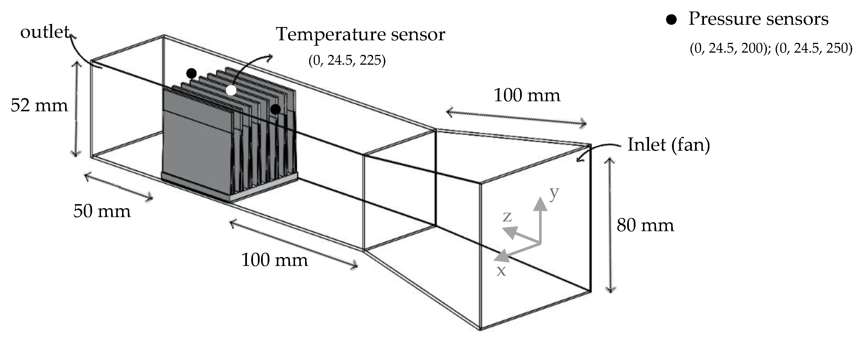
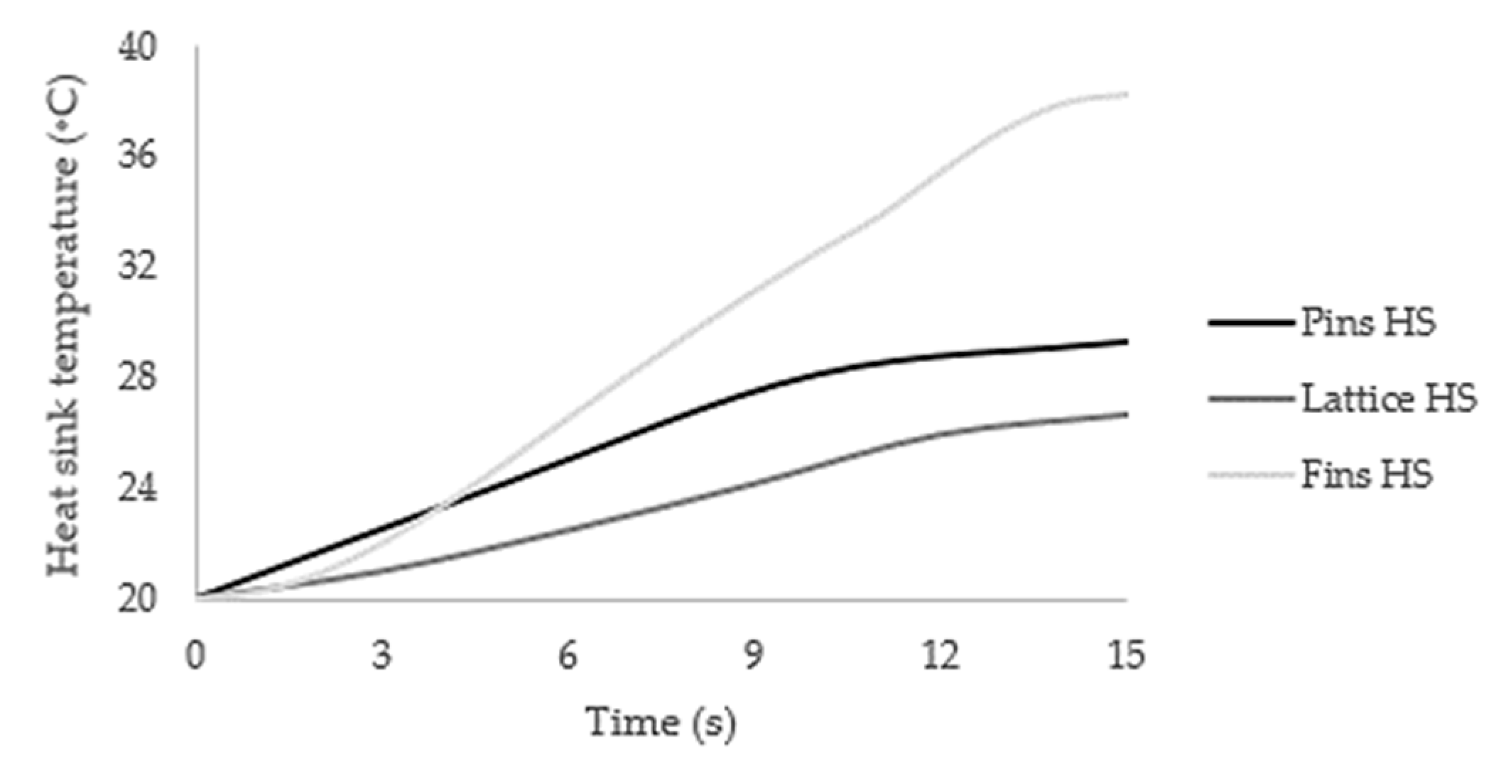
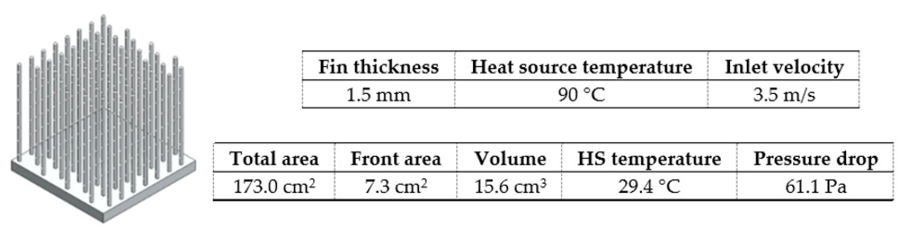
In this work, both the heat source and air flow inlet velocity are constant parameters and were defined at the base of the heat sink and the beginning of the wind tunnel, respectively. The performance of a heat sink design was evaluated by measuring their temperature after 15 s of applied heat and air flow (directly correlated with the thermal resistance according to Equation (3)). Besides the temperature control, the air pressure drop after 15 s was used as an auxiliary control metric to compare studies where the temperature differential was residual or an anormal air pressure was identified.
1.1. Conventional Heat Sinks Design and Topology
Heat sink design is the most important variable for better performance. It minimizes thermal resistance by expanding the surface area available for heat transfer while ensuring that the air flows through the heat sink [
3].
Choosing the type of heat sink (pins, fins, or blades) is an ambiguous task. Under forced convection, Wong et al. [
23] defended that fins are the best choice (among fins, blades, and circular pins), while Abdelsalam et al. [
24] compared in-line blades with fins and concluded that the first was better. In its turn, Jonsson and Moshfegh [
25] tested different heat sinks models considering Reynolds numbers in a range between 3350 and 13,400 using ANSYS Fluent software and concluded that it is not favorable to use pin heat sinks at higher Reynolds numbers.
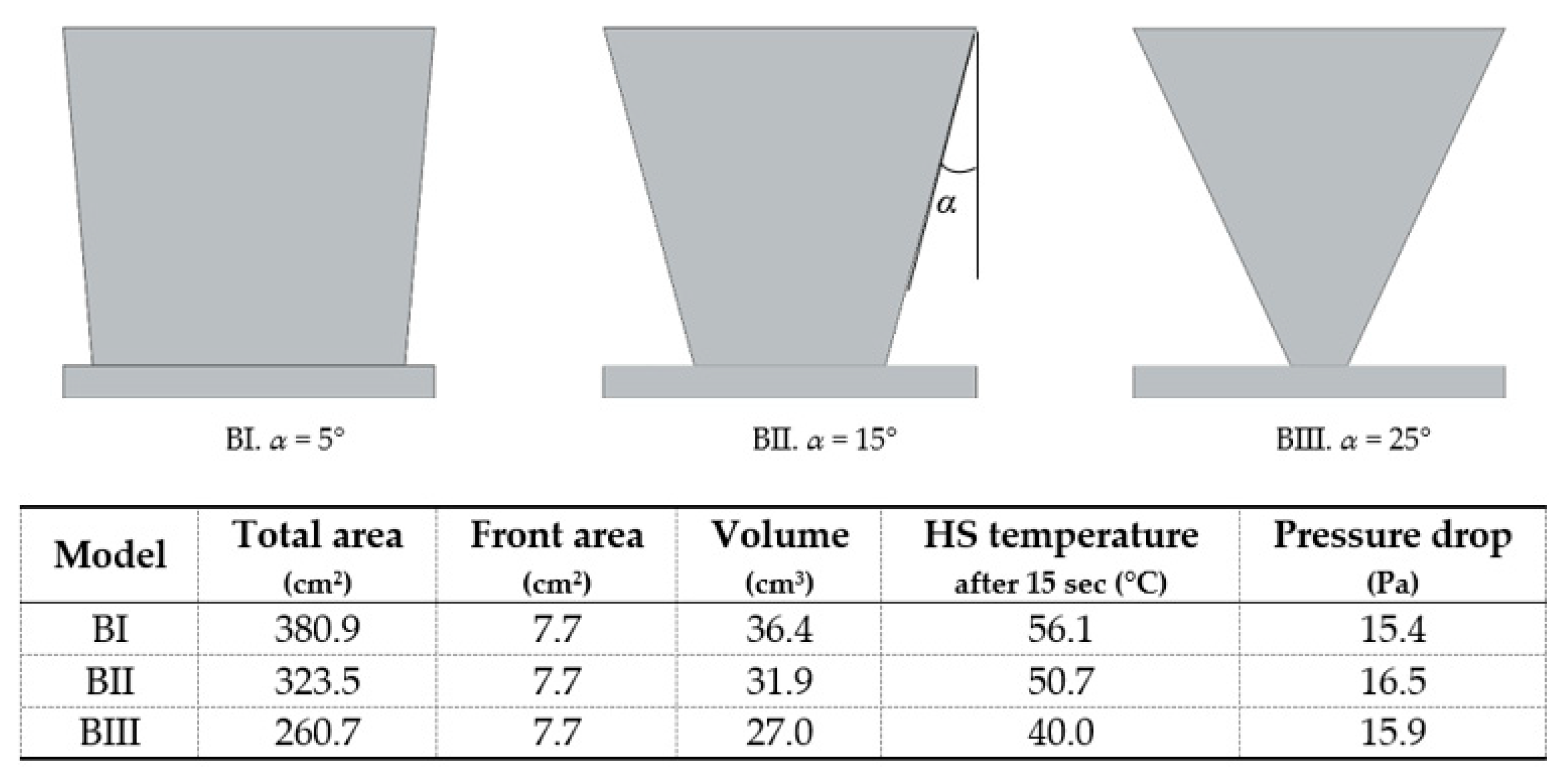
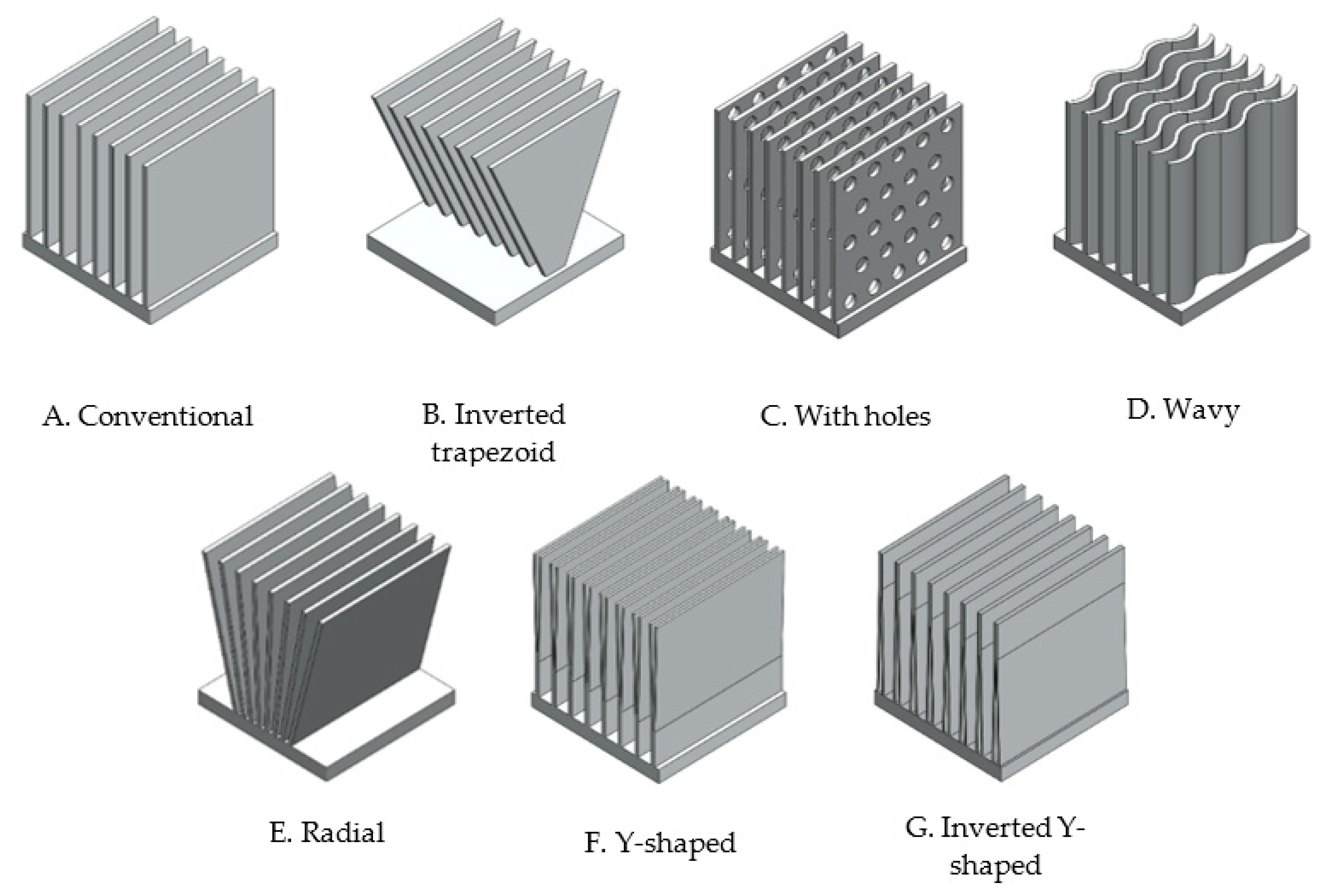
When choosing a fin heat sink, it is typical to choose the conventional rectangular fins. Still, other forms of fins have been tested, such as triangular or trapezoidal fins [
26,
27], with fillets [
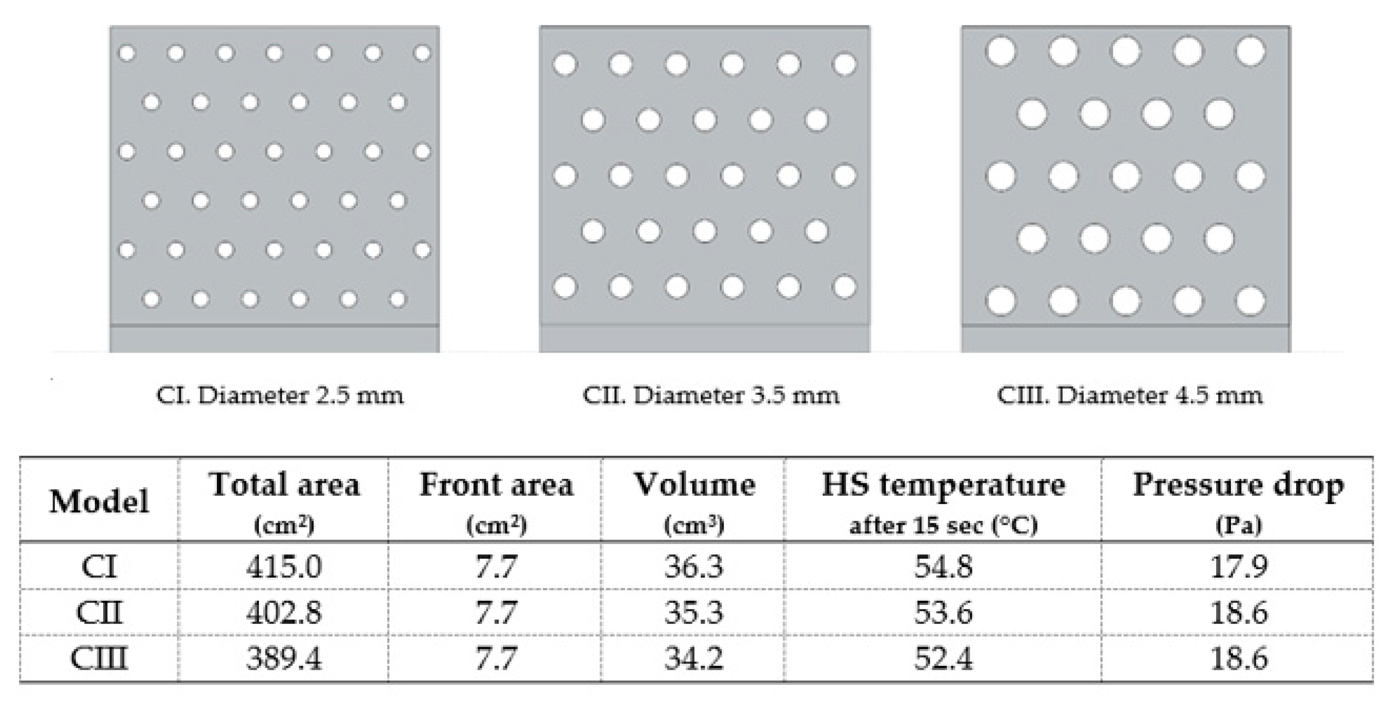
28] or holes. Jaffal [
29] analysed the thermal performance of different fin heat sinks geometries, via experimental and computational studies, at a certain heat flux interval. It was found that the heat transfer coefficient is dependent on heat flux and that the heat sink with perforated blades showed the best thermal performance. Through simulations in ANSYS software, Ibrahim et al. [
30] investigated the effect of perforation geometry (circular, rectangular, and triangular) on the heat transfer of perforated fin heat sinks, under different boundary conditions. In all cases, these perforations increased the heat transfer coefficient and decreased heat sink temperature, regardless of perforation geometry. Tijani and Jaffri [
31] also studied the effect of circular perforations on pins or fins heat sinks under forced convection. Inlet velocity and heat flux were constant and perforated pins or fins had the highest heat transfer coefficients, improving thermal efficiency up to 4% compared to solid pins or fins.
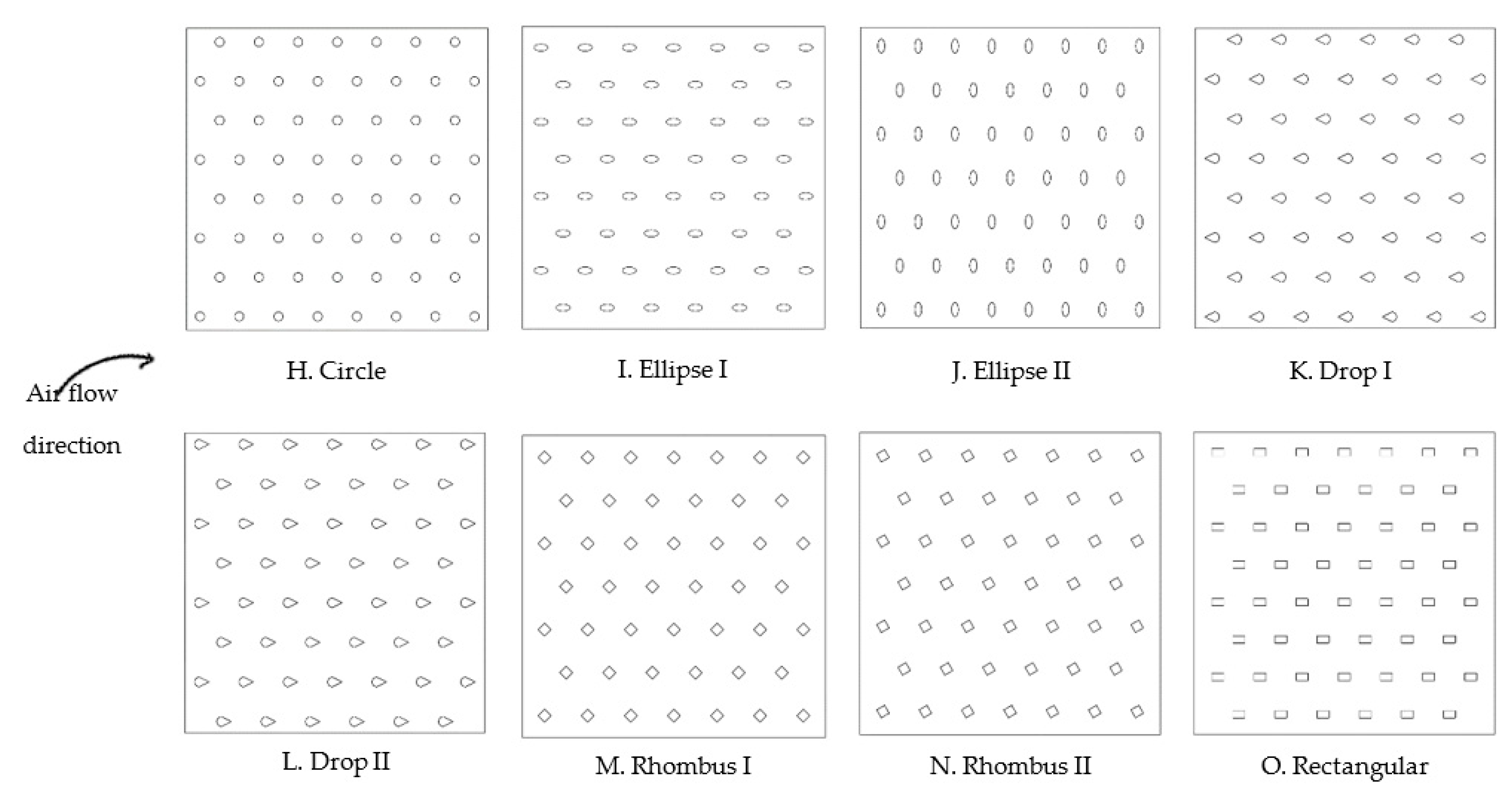
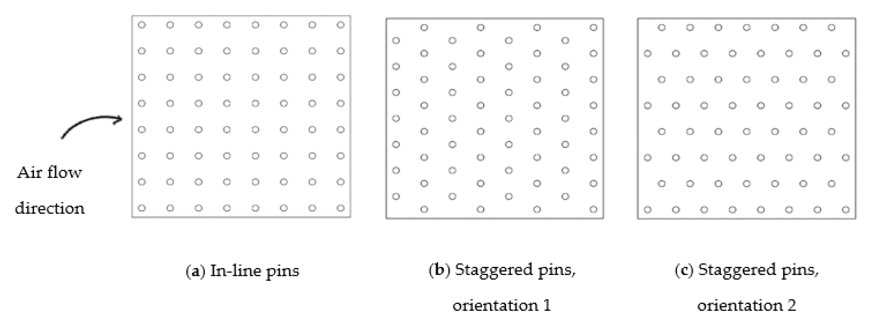
When choosing a pin heat sink, several authors agree that square pins are not a good choice [
32,
33,
34] and that pressure drop is higher when pins arrangement is staggered [
25,
35,
36,
37]. However, there is no agreement regarding the best pins shape. Under forced convection, either circular [
33,
38], elliptical [
32,
39,
40,
41,
42], dropform [
43,
44], and rhombus [
45,
46] can be advantageous. Gururatana and Li [
40] compared elliptic and rectangular staggered pins with the same length-to-thickness ratio but with different hydraulic diameters. As boundary conditions, an inlet velocity of 6 m/s at 27 °C rendered a Reynolds number of 1192 (laminar flow). Through ANSYS Fluent simulations, they concluded that elliptic fins produced a higher heat transfer rate when the pressure drop is the same. Moreover, Zhou and Catton [
39] investigated the thermal and hydraulic performance of different pin heat sinks with distinct pins shapes including square, circular, elliptic, and dropform. The elliptic pins had the best overall performance, regardless of inlet velocity and the ratio of pin widths to pins spacing. There are still other unusual shapes that can be a good choice [
47,
48]. Maji et al. [
47] investigated the thermal performance of heat sinks with perforated circular pins. Results were taken for Reynolds numbers from 4700 to 44,500 and concluded that, up to a certain perforated area, perforated pins required lower pumping power than solid pins to reach the same thermal performance. Perforated pins were also investigated by other authors that also agree on their advantages [
49,
50].
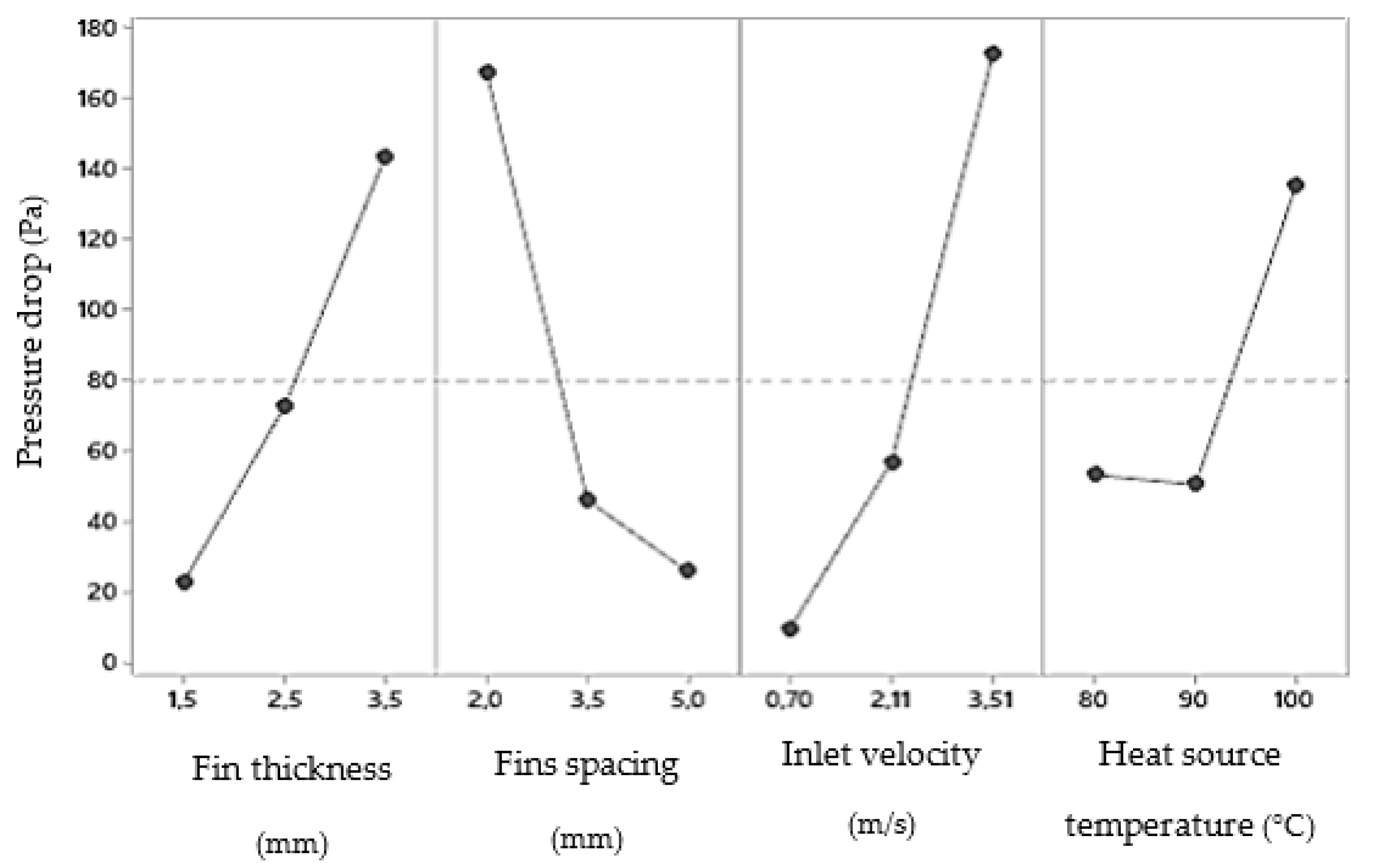
The greatest fin or pin spacing is dependent on the air velocity, i.e., as the velocity increases, the fin spacing can decrease [
3,
51]. However, the dependence of heat transfer with fin or pin spacing is not clear. According to some authors [
37,
39,
44], the heat transfer increases with increasing fin or pin density, i.e., with reduced spacing. Contrarily, according to other authors, greater heat transfer is obtained for the opposite [
37,
52,
53].
1.2. Lattice Heat Sinks
As mentioned above, in the field of electronics cooling, where oversized heat sinks are inhibited by volume constraints, the use of additive manufacturing offers the ability to deliver components without the design restrictions of conventional manufacturing methods [
48,
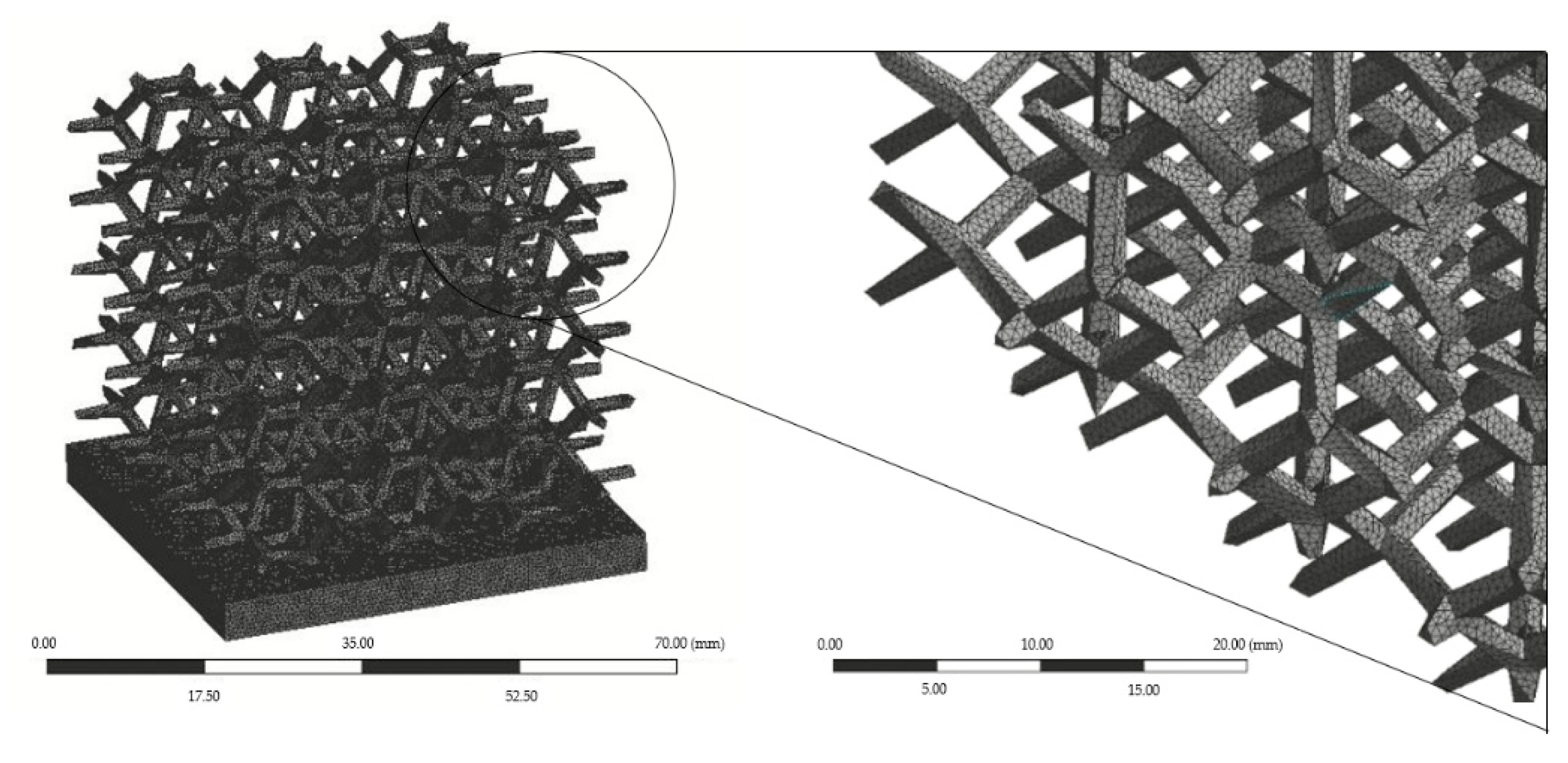
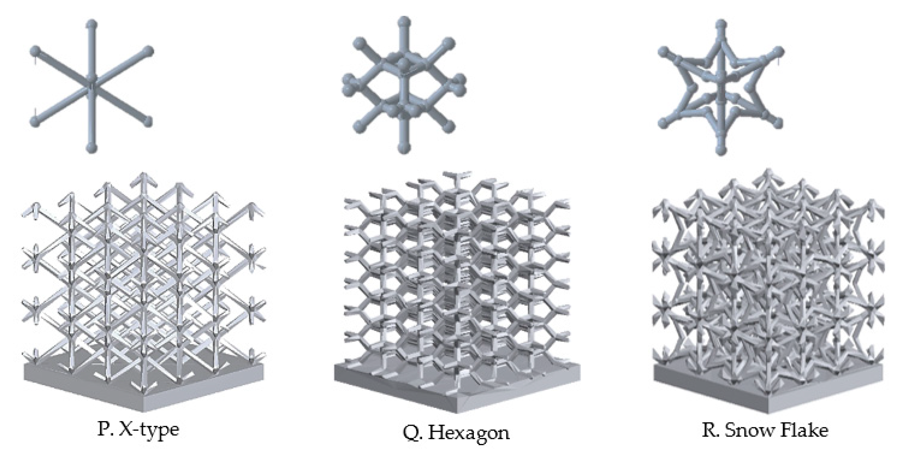
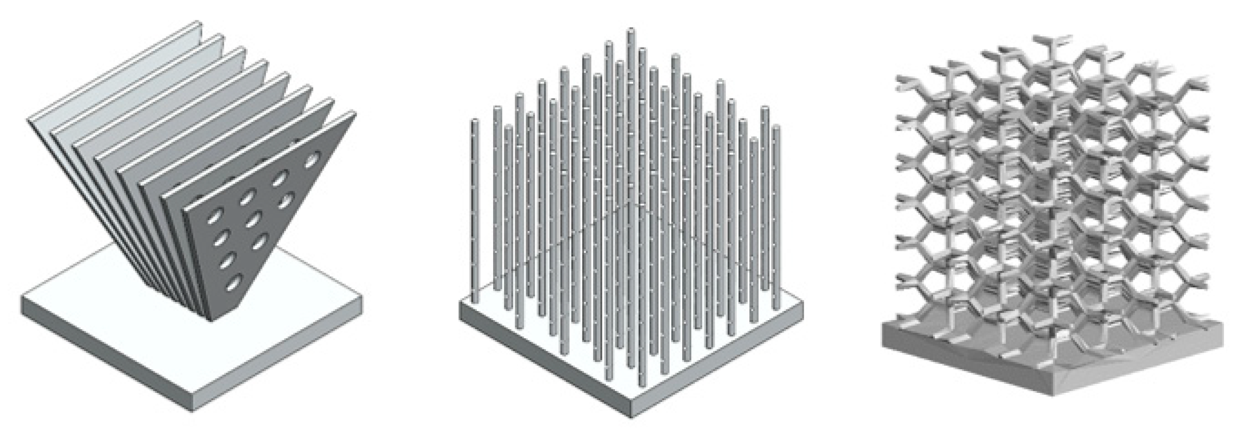
54]. Lattice structures have showed high potential in increasing forced convection heat transfer. They consist of orderly unit cell arrangements, which can have different configurations such as hexagon, honeycomb, and pyramidal [
55]. They have large surface area-to-volume ratios, are light, and promote tortuous fluid paths, promoting fluid mixing. Their advantage over metal foams are constant periodicity and homogeneity allowing optimization of the ligament configuration and diameter, better mechanical properties, and greater ease of production with emerging additive manufacturing technologies [
54,
55,
56]. The study of the fluid flow through them has become popular in thermal management [
55,
56,
57,
58,
59].
Although the lattice structure heat sink allows a high surface area to volume ratios, its performance may be limited by the absense of interaction between the cooling air and structure [
7]. According to Ho et al. [
55], pressure drop and Nusselt number of Rhombi-Octet lattice structures increased with decreasing unit cell size and the highest Nusselt number was obtained with the lattice structure with the smallest ligament width. The same conclusion was obtained by Son et al. [
60].
Regarding the best unit cell topology for thermal management, there is no clear conclusion. For example, according to Yan et al. [
61], the X-type lattice heat sink provides overall heat removal capacity up to two times higher than tetrahedral or the Kagome lattice heat sink. Its morphology resulted in a large scale spiral main flow that interacts with several secondary flows, causing three times higher pressure drop for a given Reynolds number. Still, superior heat transfer was achieved by the X-type lattice. The same conclusion was not made by Hyun and Torquato [
62]. They suggested that Kagome structures have desirable heat-dissipation properties due to the large hexagonal holes through which fluid may flow, compared to triangular and hexagonal cells. More recently, Dixit et al. [
63] concluded that octet topology dissipates more heat at the lowest Reynolds numbers while SC-BCC-truss outperforms other architectures as the fluid velocity increases.


