
A Dual Resonance Electromagnetic Vibration Energy Harvester for Wide Harvested Frequency Range with Enhanced Output Power


Abstract
:1. Introduction
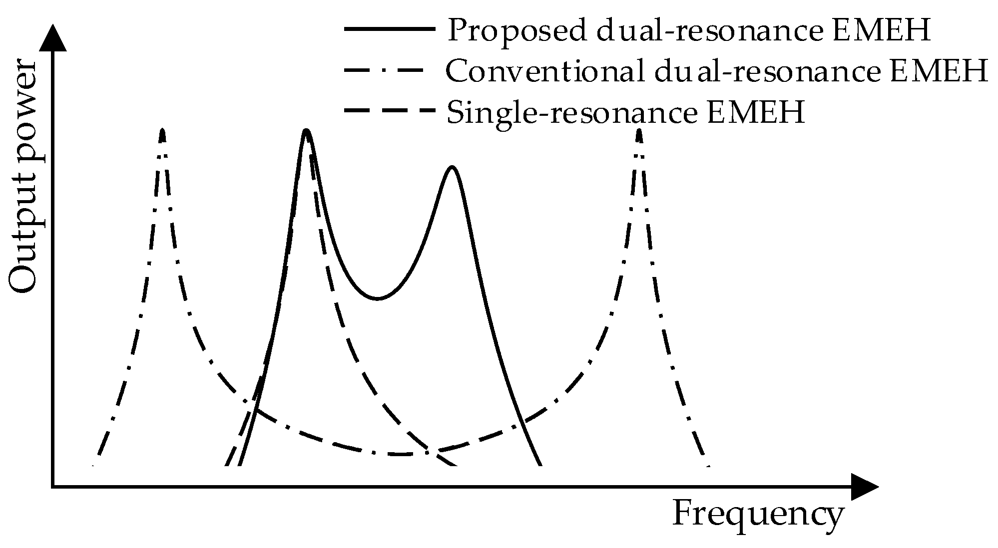
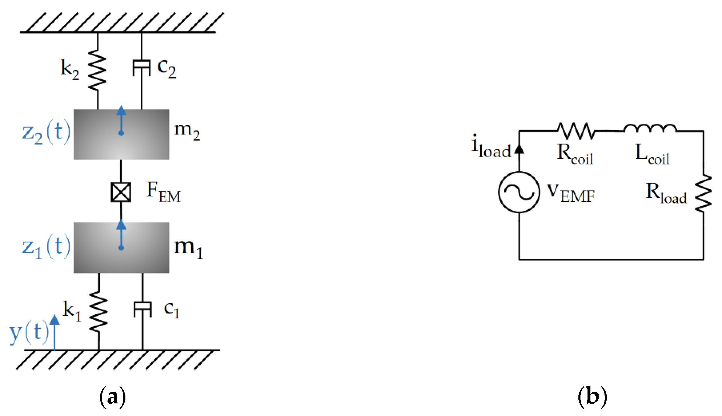
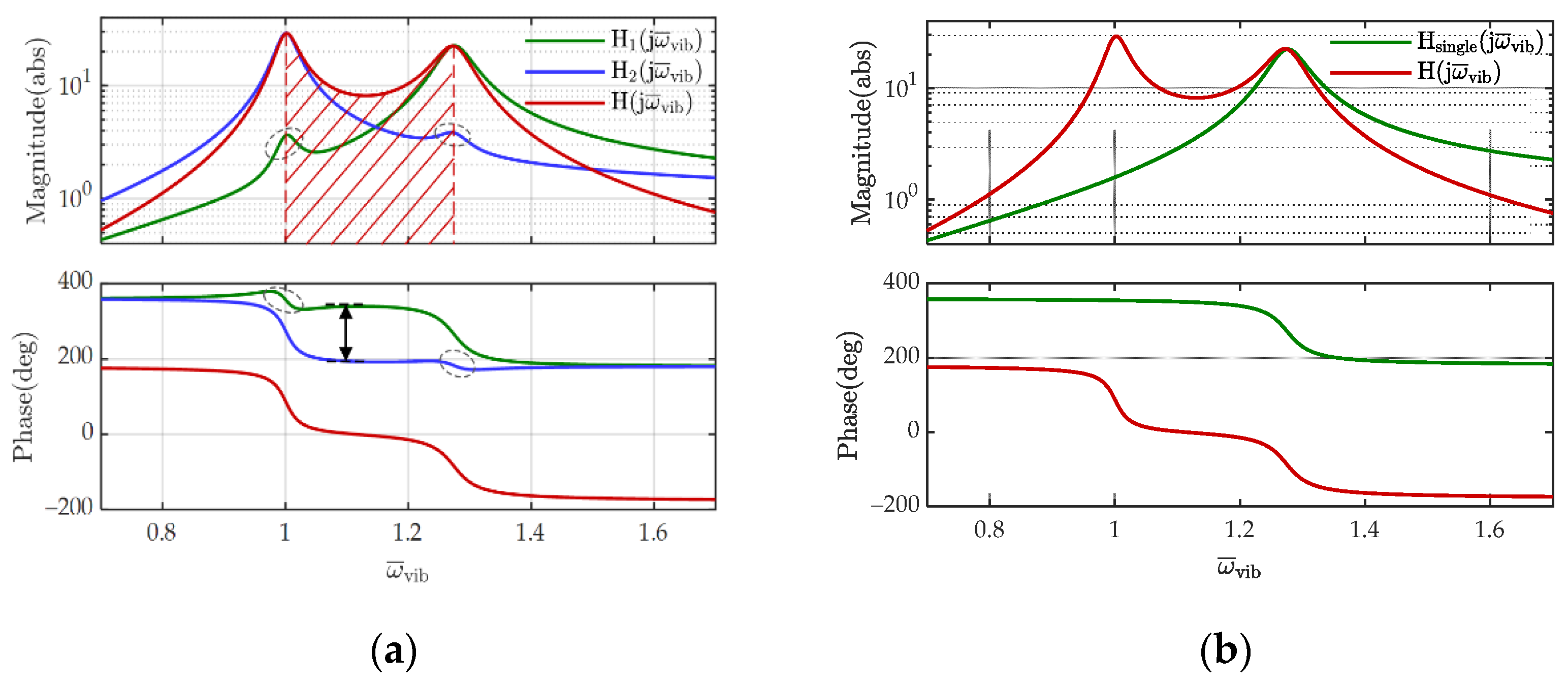
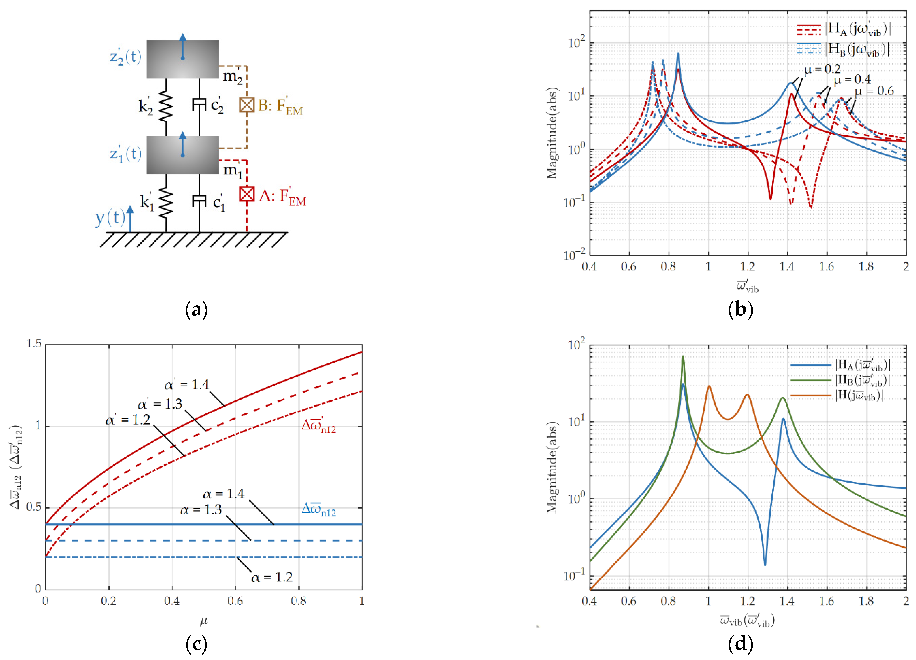
2. Basic Theorem and Frequency Range Extension of the Proposed Dual Resonance EMEH
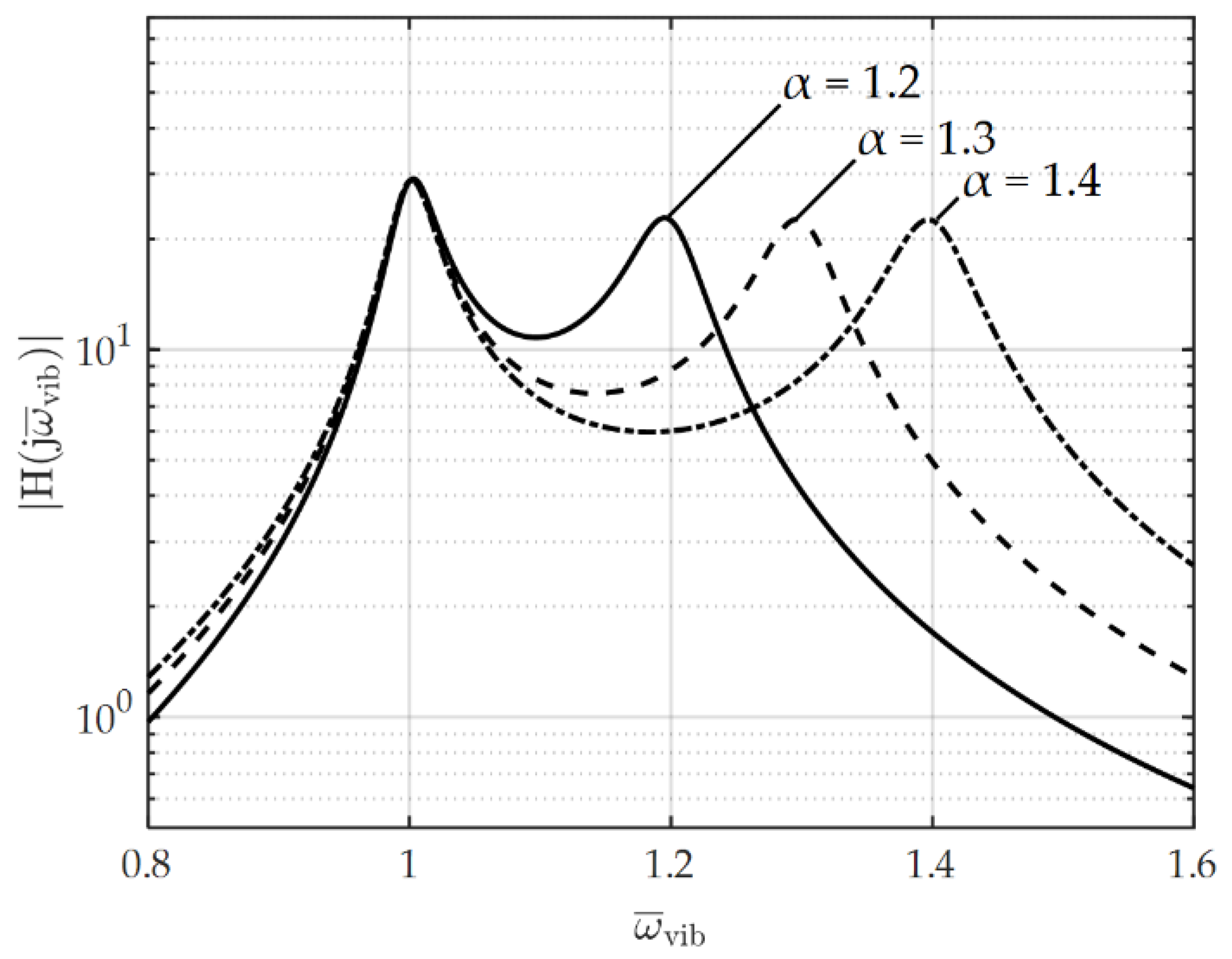
3. Resonant Angular Frequency of the Dual Resonance Electromagnetic EH
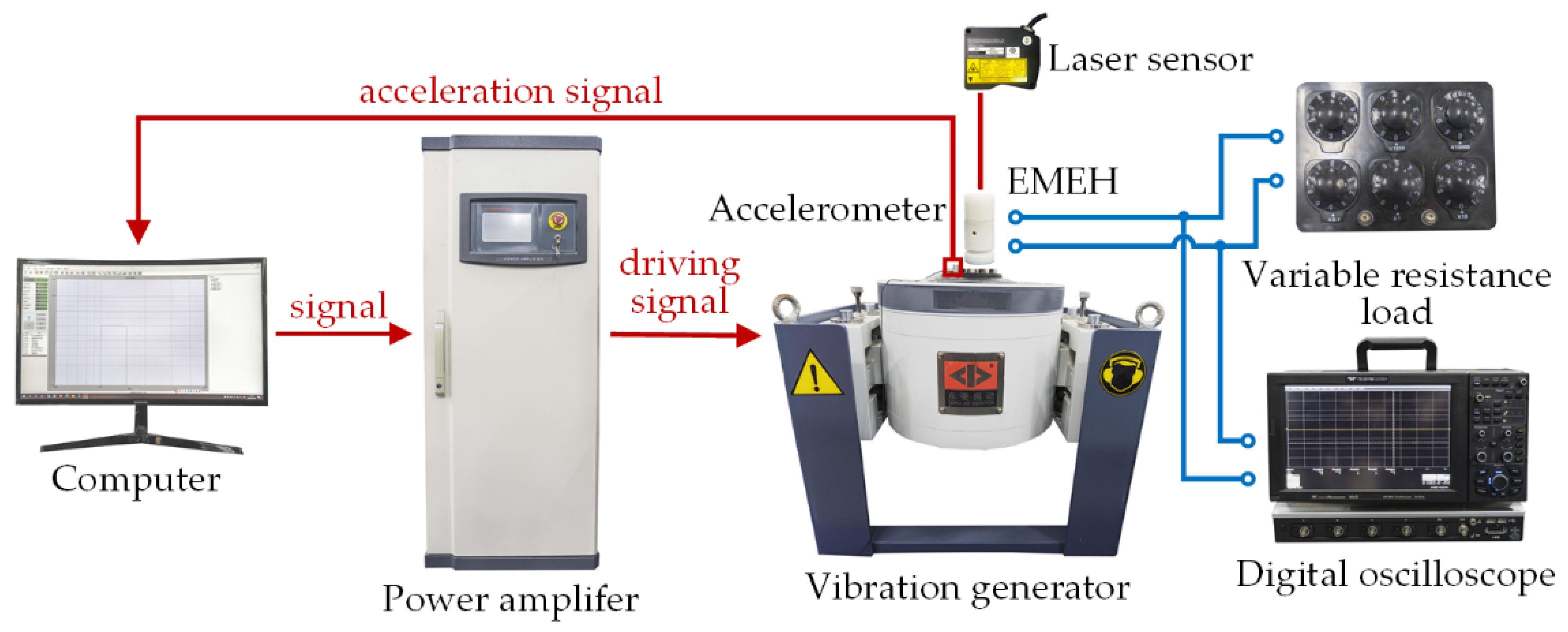
4. Prototype Design and Experiment Verification
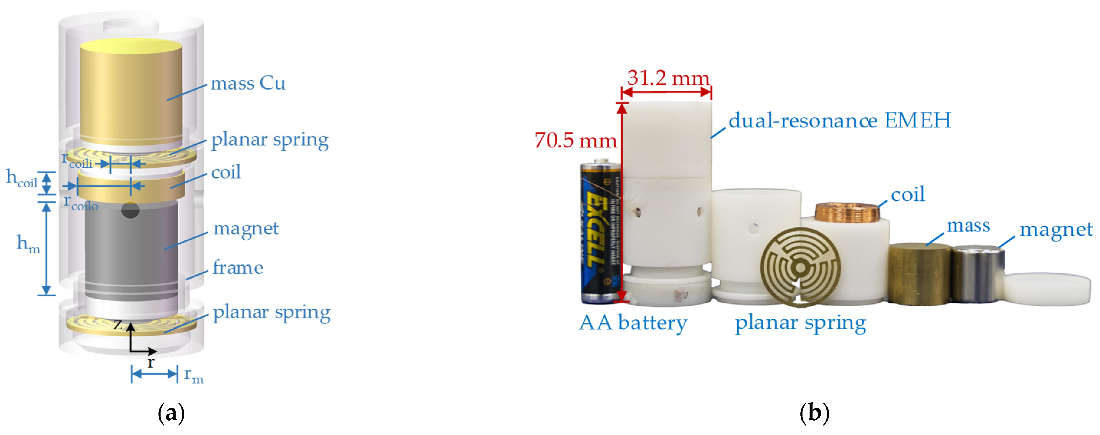
4.1. Prototype Design
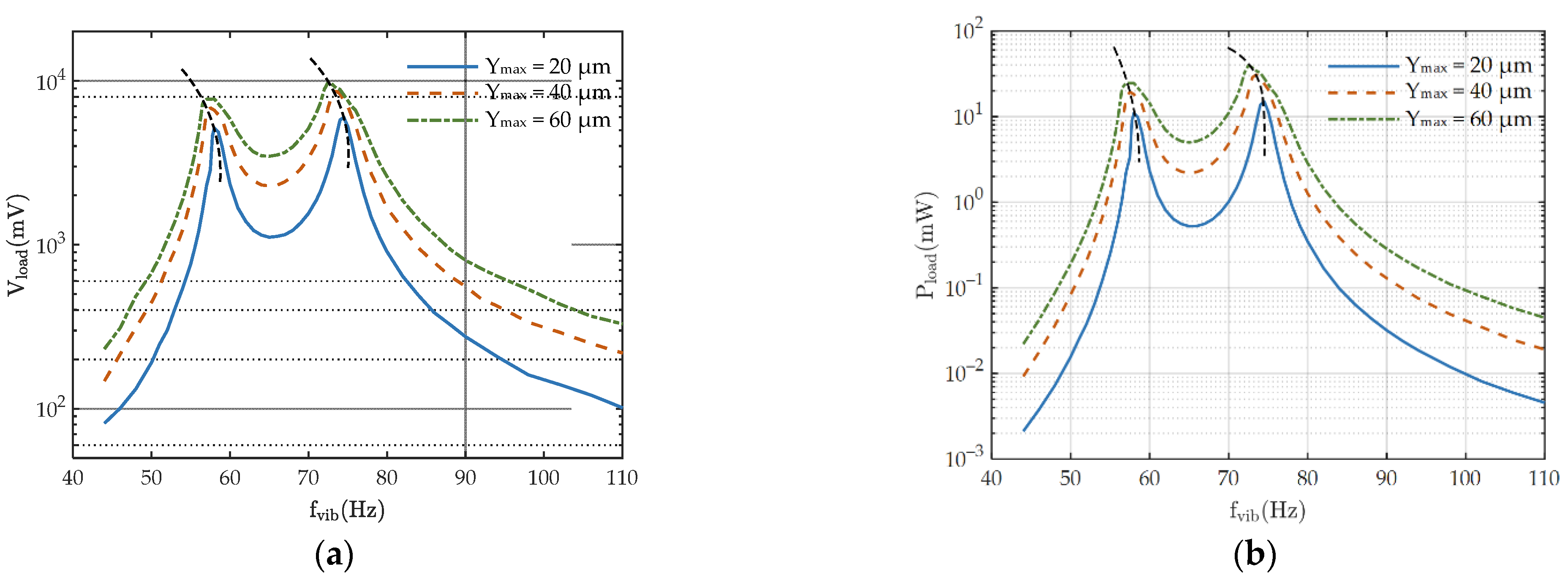
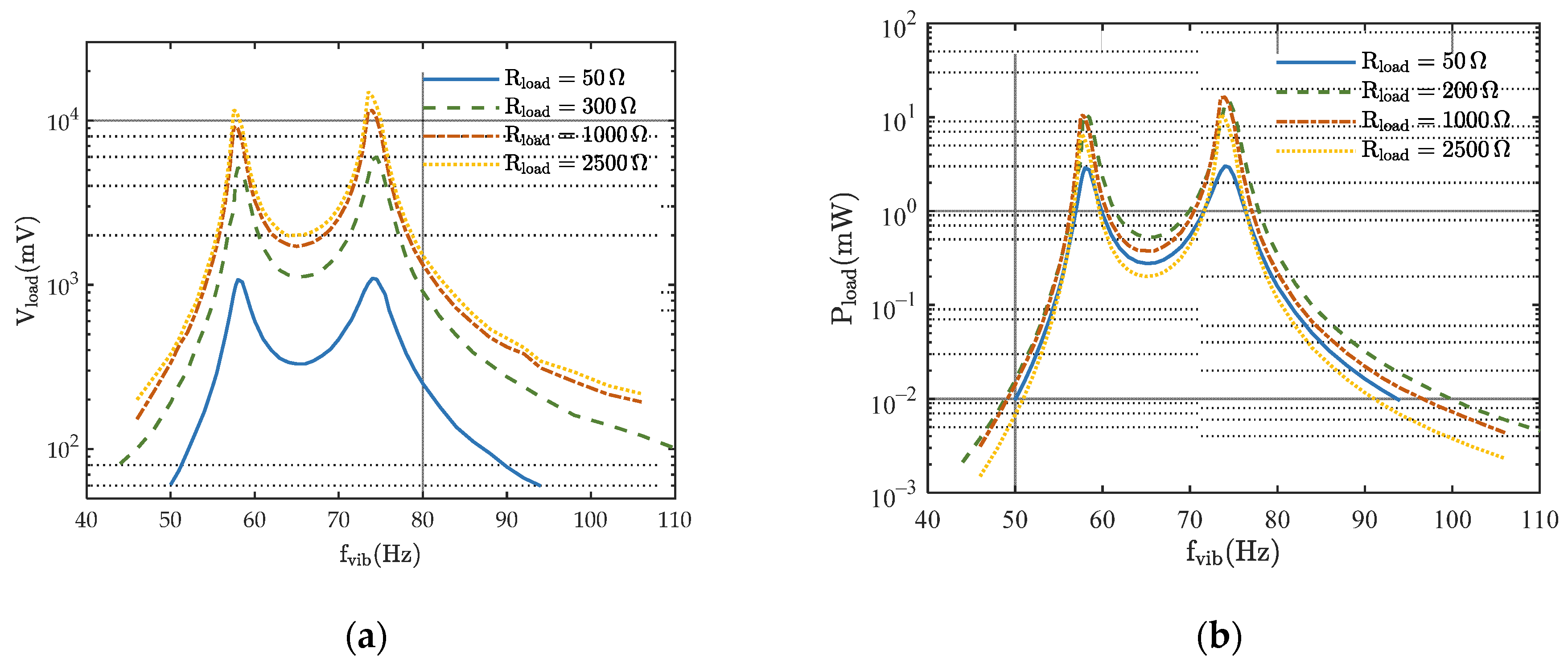
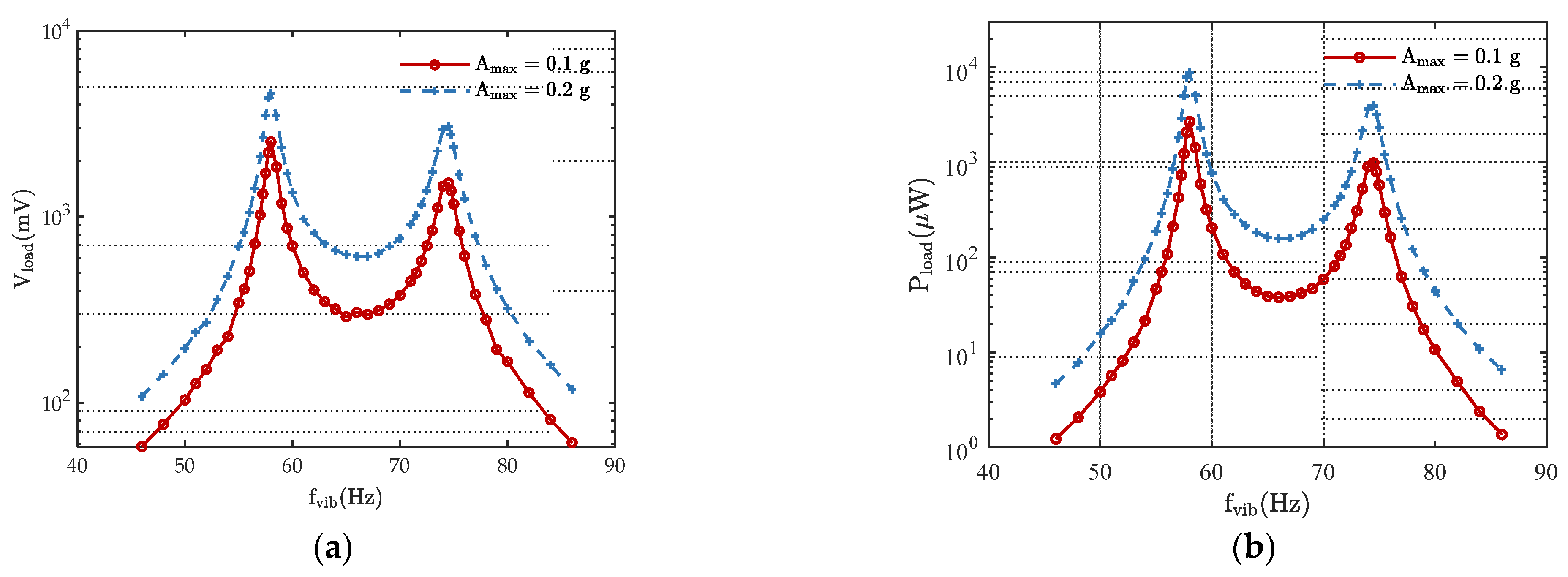
4.2. Experimental Results and Discussion
5. Conclusions
Author Contributions
Funding
Institutional Review Board Statement
Informed Consent Statement
Data Availability Statement
Conflicts of Interest
References
- Priya, S.; Inman, D.J. Energy Harvesting Technologies, 1st ed.; Springer US: Boston, MA, USA, 2008. [Google Scholar]
- Citroni, R.; Di Paolo, F.; Livreri, P. A Novel Energy Harvester for Powering Small UAVs: Performance Analysis, Model Validation and Flight Results. Sensors 2019, 19, 1771. [Google Scholar] [CrossRef] [Green Version]
- Citroni, R.; Di Paolo, F.; Livreri, P. Evaluation of an optical energy harvester for SHM application. AEU Int. J. Electron. Commun. 2019, 111, 152918. [Google Scholar] [CrossRef]
- Gu, Y.; Liu, W.; Zhao, C.; Wang, P. A goblet-like non-linear electromagnetic generator for planar multi-directional vibration energy harvesting. Appl. Energy 2020, 266, 114846. [Google Scholar] [CrossRef]
- Zhang, J.; Su, Y. Design and analysis of a non-resonant rotational electromagnetic harvester with alternating magnet sequence. J. Magn. Magn. Mater. 2021, 540, 168393. [Google Scholar] [CrossRef]
- Zhou, N.; Hou, Z.; Zhang, Y.; Cao, J.; Bowen, C.R. Enhanced swing electromagnetic energy harvesting from human motion. Energy 2021, 228, 120591. [Google Scholar] [CrossRef]
- Williams, C.B.; Shearwood, C.; Harradine, M.A.; Mellor, P.H.; Birch, T.S.; Yates, R.B. Development of an electromagnetic micro-generator. IEE P-Circ. Dev. Syst. 2001, 148, 337–342. [Google Scholar] [CrossRef]
- Stephen, N.G. On energy harvesting from ambient vibration. J. Sound Vib. 2006, 293, 409–425. [Google Scholar] [CrossRef] [Green Version]
- Chen, Y.; Peng, H.; Cheng, Z.; Tong, Q.; Kang, Y. A Planar PCB Based Energy Harvester with Voltage Multiplier. In Proceedings of the 2020 IEEE Energy Conversion Congress and Exposition (ECCE), Detroit, MI, USA, 11–15 October 2020; pp. 975–980. [Google Scholar]
- Makovička, D. Response Analysis of Building Loaded by Groundborne Transient Vibration. In Proceedings of the III European Conference on Computational Mechanics, Lisbon, Portugal, 5–8 June 2006; p. 748. [Google Scholar]
- Tang, L.; Yang, Y.; Soh, C.K. Toward Broadband Vibration-based Energy Harvesting. J. Intel. Mat. Syst. Str. 2010, 21, 1867–1897. [Google Scholar] [CrossRef]
- Foisal, A.R.M.; Hong, C.; Chung, G. Multi-frequency electromagnetic energy harvester using a magnetic spring cantilever. Sens. Actuators A Phys. 2012, 182, 106–113. [Google Scholar] [CrossRef]
- Ferrari, M.; Ferrari, V.; Guizzetti, M.; Marioli, D.; Taroni, A. Piezoelectric multifrequency energy converter for power harvesting in autonomous microsystems. Sens. Actuators A Phys. 2008, 142, 329–335. [Google Scholar] [CrossRef]
- Challa, V.R.; Prasad, M.G.; Fisher, F.T. Towards an autonomous self-tuning vibration energy harvesting device for wireless sensor network applications. Smart Mater. Struct. 2011, 20, 0250042. [Google Scholar] [CrossRef] [Green Version]
- Mann, B.P.; Sims, N.D. Energy harvesting from the nonlinear oscillations of magnetic levitation. J. Sound Vib. 2009, 319, 515–530. [Google Scholar] [CrossRef] [Green Version]
- Fan, K.; Cai, M.; Liu, H.; Zhang, Y. Capturing energy from ultra-low frequency vibrations and human motion through a monostable electromagnetic energy harvester. Energy 2019, 169, 356–368. [Google Scholar] [CrossRef]
- Palagummi, S.; Yuan, F.G. A bi-stable horizontal diamagnetic levitation based low frequency vibration energy harvester. Sens. Actuators A Phys. 2018, 279, 743–752. [Google Scholar] [CrossRef]
- Podder, P.; Amann, A.; Roy, S. Combined Effect of Bistability and Mechanical Impact on the Performance of a Nonlinear Electromagnetic Vibration Energy Harvester. IEEE-Asme T Mech. 2016, 21, 727–739. [Google Scholar] [CrossRef]
- Halim, M.A.; Cho, H.; Park, J.Y. Design and experiment of a human-limb driven, frequency up-converted electromagnetic energy harvester. Energy Convers. Manag. 2015, 106, 393–404. [Google Scholar] [CrossRef]
- Zorlu, O.; Topal, E.T.; Kulah, H. A Vibration-Based Electromagnetic Energy Harvester Using Mechanical Frequency Up-Conversion Method. IEEE Sens. J. 2011, 11, 481–488. [Google Scholar] [CrossRef]
- Wu, Z.; Cao, Z.; Ding, R.; Wang, S.; Chu, Y.; Ye, X. An electrostatic-electromagnetic hybrid generator with largely enhanced energy conversion efficiency. Nano Energy 2021, 89, 106425. [Google Scholar] [CrossRef]
- Wu, Y.; Zeng, Q.; Tang, Q.; Liu, W.; Liu, G.; Zhang, Y.; Wu, J.; Hu, C.; Wang, X. A teeterboard-like hybrid nanogenerator for efficient harvesting of low-frequency ocean wave energy. Nano Energy 2020, 67, 104205. [Google Scholar] [CrossRef]
- Li, P.; Gao, S.; Cai, H. Modeling and analysis of hybrid piezoelectric and electromagnetic energy harvesting from random vibrations. Microsyst. Technol. 2015, 21, 401–414. [Google Scholar] [CrossRef]
- Mahmoudi, S.; Kacem, N.; Bouhaddi, N. Enhancement of the performance of a hybrid nonlinear vibration energy harvester based on piezoelectric and electromagnetic transductions. Smart Mater. Struct. 2014, 23, 075024. [Google Scholar] [CrossRef]
- Iqbal, M.; Khan, F.U. Hybrid vibration and wind energy harvesting using combined piezoelectric and electromagnetic conversion for bridge health monitoring applications. Energy Convers. Manag. 2018, 172, 611–618. [Google Scholar] [CrossRef]
- Toyabur, R.M.; Salauddin, M.; Cho, H.; Park, J.Y. A multimodal hybrid energy harvester based on piezoelectric-electromagnetic mechanisms for low-frequency ambient vibrations. Energy Convers. Manag. 2018, 168, 454–466. [Google Scholar] [CrossRef]
- Tao, K.; Wu, J.; Tang, L.; Xia, X.; Lye, S.W.; Miao, J.; Hu, X. A novel two-degree-of-freedom MEMS electromagnetic vibration energy harvester. J. Micromech. Microeng. 2016, 26, 0350203. [Google Scholar] [CrossRef]
- Hu, G.; Tang, L.; Das, R.; Marzocca, P. A two-degree-of-freedom piezoelectric energy harvester with stoppers for achieving enhanced performance. Int. J. Mech. Sci. 2018, 149, 500–507. [Google Scholar] [CrossRef]
- Wang, H.; Tang, L. Modeling and experiment of bistable two-degree-of-freedom energy harvester with magnetic coupling. Mech. Syst. Signal. Process. 2017, 86, 29–39. [Google Scholar] [CrossRef]
- Wang, Z.; Ding, H.; Chen, L. Nonlinear oscillations of a two-degree-of-freedom energy harvester of magnetic levitation. J. Vib. Shock 2016, 35, 55–58. [Google Scholar]
- Cammarano, A.; Burrow, S.G.; Barton, D.A.W.; Carrella, A.; Clare, L.R. Tuning a resonant energy harvester using a generalized electrical load. Smart Mater. Struct. 2010, 19, 0550035. [Google Scholar] [CrossRef]
- Tang, L.; Yang, Y. A multiple-degree-of-freedom piezoelectric energy harvesting model. J. Intell. Mat. Syst. Struct. 2012, 23, 1631–1647. [Google Scholar] [CrossRef]
- Xiao, H.; Wang, X.; John, S. A dimensionless analysis of a 2DOF piezoelectric vibration energy harvester. Mech. Syst. Signal. Process. 2015, 58–59, 355–375. [Google Scholar] [CrossRef]
- Barillaro, G.; Molfese, A.; Nannini, A.; Pieri, F. Analysis, simulation and relative performances of two kinds of serpentine springs. J. Micromech. Microeng. 2005, 15, 736–746. [Google Scholar] [CrossRef]
- Cepnik, C.; Radler, O.; Rosenbaum, S.; Stroehla, T.; Wallrabe, U. Effective optimization of electromagnetic energy harvesters through direct computation of the electromagnetic coupling. Sens. Actuators A Phys. 2011, 167, 416–421. [Google Scholar] [CrossRef]
- Spreemann, D.; Manoli, Y. Electromagnetic Vibration Energy Harvesting Devices: Architectures, Design, Modeling and Optimization; Springer Science & Business Media: Dordrecht, The Netherlands, 2012; Volume 35. [Google Scholar]
- Dayal, R.; Dwari, S.; Parsa, L. A New Design for Vibration-Based Electromagnetic Energy Harvesting Systems Using Coil Inductance of Microgenerator. IEEE T Ind. Appl. 2011, 47, 820–830. [Google Scholar] [CrossRef]
- Wang, P. Study on the Micro Electromagnetic Vibration Energy Harvester Based on MEMS Technology. Ph.D. Thesis, Shanghai Jiao Tong University, Shanghai, China, 2010. [Google Scholar]
- Arnold, D.P. Review of microscale magnetic power generation. IEEE T Magn. 2007, 43, 3940–3951. [Google Scholar] [CrossRef]
- Fan, K.; Zhang, Y.; Liu, H.; Cai, M.; Tan, Q. A nonlinear two-degree-of-freedom electromagnetic energy harvester for ultra-low frequency vibrations and human body motions. Renew. Energy 2019, 138, 292–302. [Google Scholar] [CrossRef]


| Parameter | Description | Value |
|---|---|---|
| m1, m2 | Mass 1, Mass 2 | 76 g, 46 g |
| Ymax | Vibration source amplitude | 20, 40, 60 μm |
| Rcoil | Internal resistance of coil | 273 Ω |
| Lcoil | Internal inductance of coil | 77.8 mH |
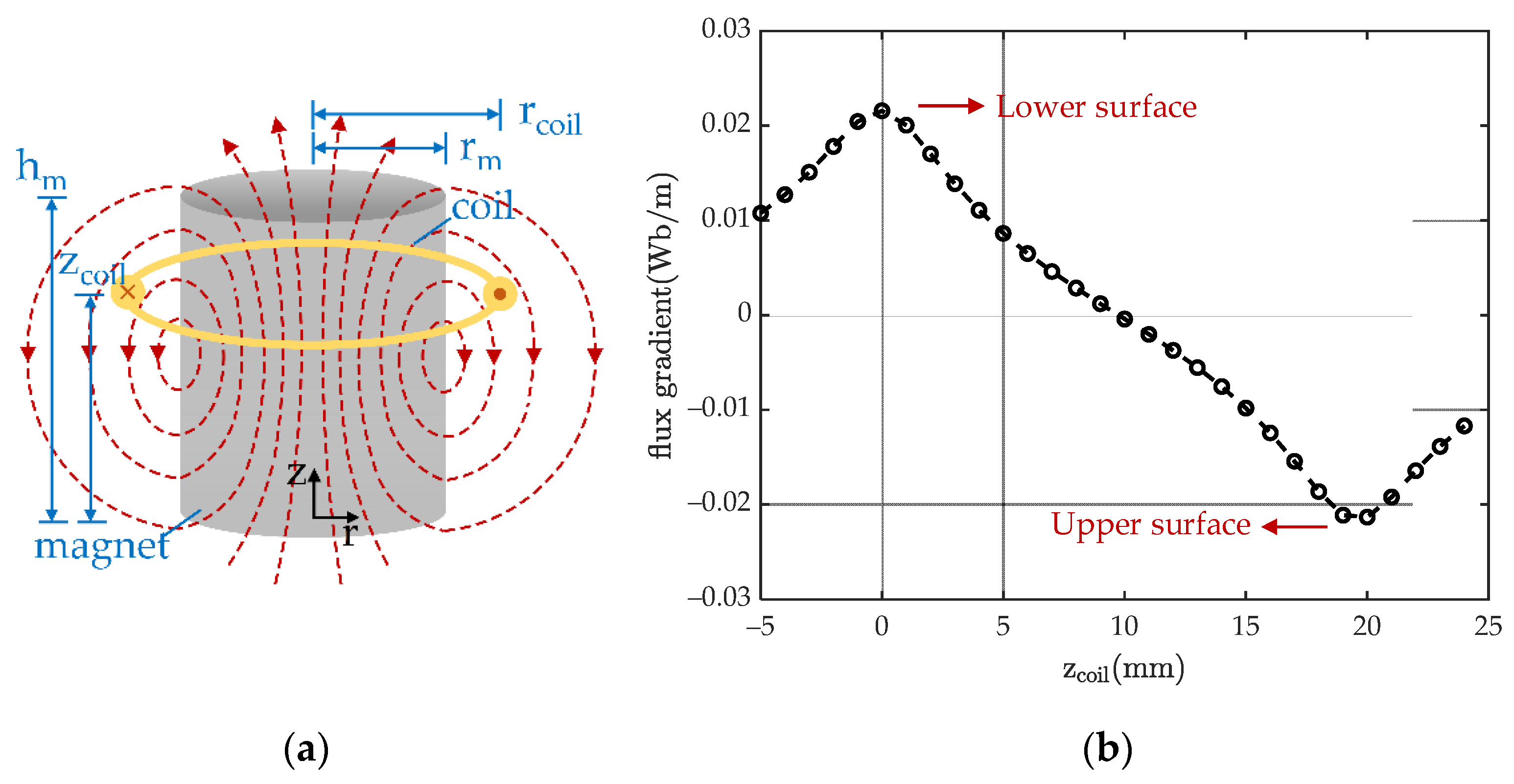
| rm | Magnet radius and height | 9.9 mm |
| hm | Magnet height | 19.5 mm |
| Br | Remanent magnetic flux density of magnet | 1.23 T |
| hcoil | Ring coil height | 5 mm |
| rcoili | Ring coil inner radius | 5.2 mm |
| rcoilo | Ring coil outer radius | 11.5 mm |
| Ncoil | Ring coil turns | 2350 |
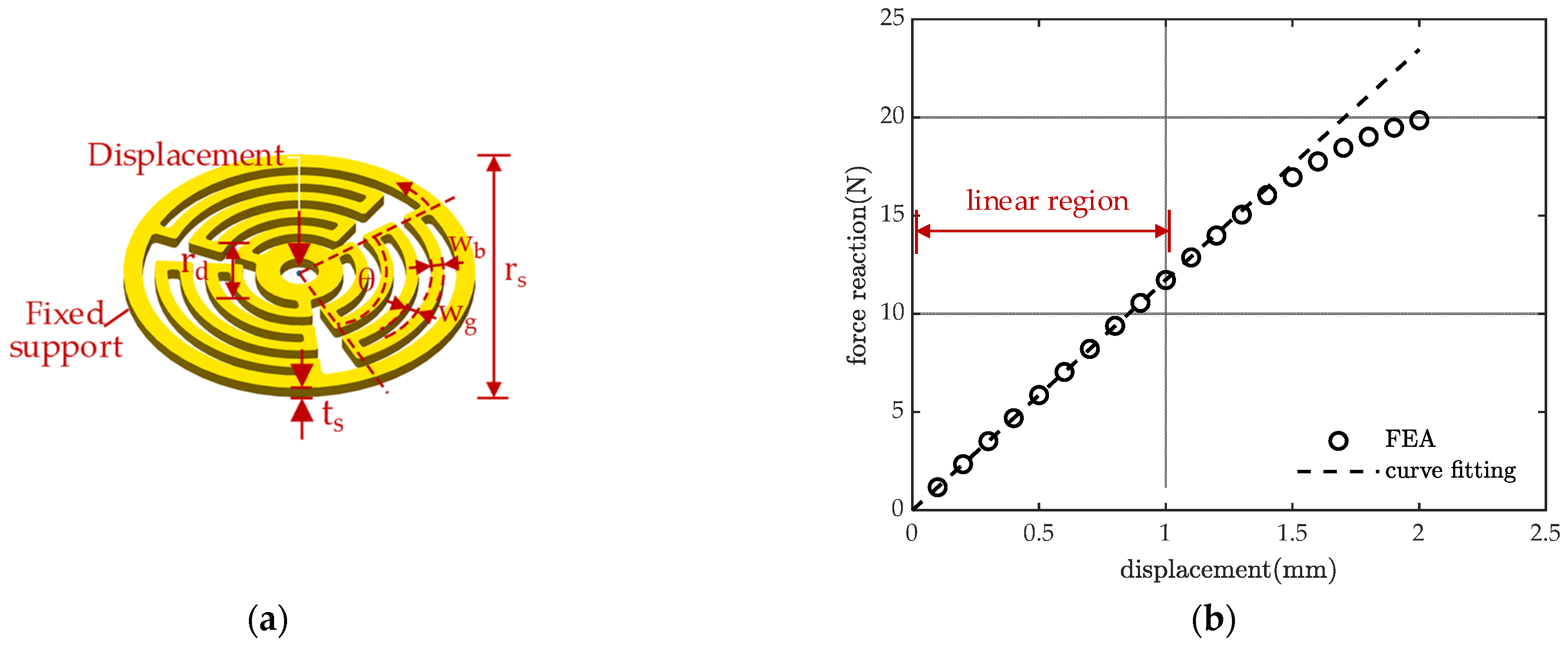
| θ | Spring sector angle | 100° |
| ts | Spring thickness | 0.9 mm |
| wb | Spring beam width | 1 mm |
| wg | Spring beam gap width | 1 mm |
| rd | Spring central disc radius | 3.5 mm |
| rs | Spring outer radius | 14 mm |
| Ref | Transduction Type and Employed Technology | Spring Type | Resonant Frequencies (Hz) | Max. Output Power (mW) | Volume (cm3) | Max. NPD (mW/(cm3·g2)) | S (mW/(s·cm3·g2)) |
|---|---|---|---|---|---|---|---|
| [40] | Electromagnetic; dual resonance, nonlinear | Magnetic spring | 7.5, 18.5 | 2.58 @ 7.5 Hz, 0.5 g | 9.73 | 1.06 | 5.2247 |
| [27] | Electromagnetic; dual resonance | MEMS planar spring | 326, 391 | 9.6 × 10⁻⁷ @ 391 Hz, 0.12 g | 0.29 | 2.3 × 10⁻⁴ | null |
| [12] | Electromagnetic; EH array | Magnetic spring | 7, 8, 9, 10 | 2.09 @ 8.5 Hz, 0.5 g | 40.18 | 0.208 @ 8.5 Hz, 0.5 g | 0.681 |
| [18] | Electromagnetic; bi-stable EH | FR4 spring | 36 | 0.0193 @ 36 Hz, 1.5 g | ~1.171 | 7.325 × 10⁻³ | null |
| [19] | Electromagnetic; up-conversion | Helical spring | null | 11.89 @ 5.17 Hz, 2.06 g | 6.47 | 0.07847 | null |
| [16] | Electromagnetic; nonlinear | Magnetic and helical springs | 9 | 1.15 @ 9 Hz, 0.8 g | 12.2 | 0.1473 | 0.7352 |
| This Work | Electromagnetic; dual-resonance | Planar spring | 58, 74.5 | 39.8 @74.5 Hz, 0.45 g | 53.9 | 2.77 @ 58 Hz, 0.27 g | 10.53 @ 53.4–79.7 Hz |
Publisher’s Note: MDPI stays neutral with regard to jurisdictional claims in published maps and institutional affiliations. |
© 2021 by the authors. Licensee MDPI, Basel, Switzerland. This article is an open access article distributed under the terms and conditions of the Creative Commons Attribution (CC BY) license (https://creativecommons.org/licenses/by/4.0/).
Share and Cite
Feng, Z.; Peng, H.; Chen, Y. A Dual Resonance Electromagnetic Vibration Energy Harvester for Wide Harvested Frequency Range with Enhanced Output Power. Energies 2021, 14, 7675. https://doi.org/10.3390/en14227675
Feng Z, Peng H, Chen Y. A Dual Resonance Electromagnetic Vibration Energy Harvester for Wide Harvested Frequency Range with Enhanced Output Power. Energies. 2021; 14(22):7675. https://doi.org/10.3390/en14227675
Chicago/Turabian StyleFeng, Zhijie, Han Peng, and Yong Chen. 2021. "A Dual Resonance Electromagnetic Vibration Energy Harvester for Wide Harvested Frequency Range with Enhanced Output Power" Energies 14, no. 22: 7675. https://doi.org/10.3390/en14227675
APA StyleFeng, Z., Peng, H., & Chen, Y. (2021). A Dual Resonance Electromagnetic Vibration Energy Harvester for Wide Harvested Frequency Range with Enhanced Output Power. Energies, 14(22), 7675. https://doi.org/10.3390/en14227675