
In Vitro and In Vivo Biocompatibility Studies of a Cast and Coated Titanium Alloy

 ,
,
Abstract
:1. Introduction
2. Results
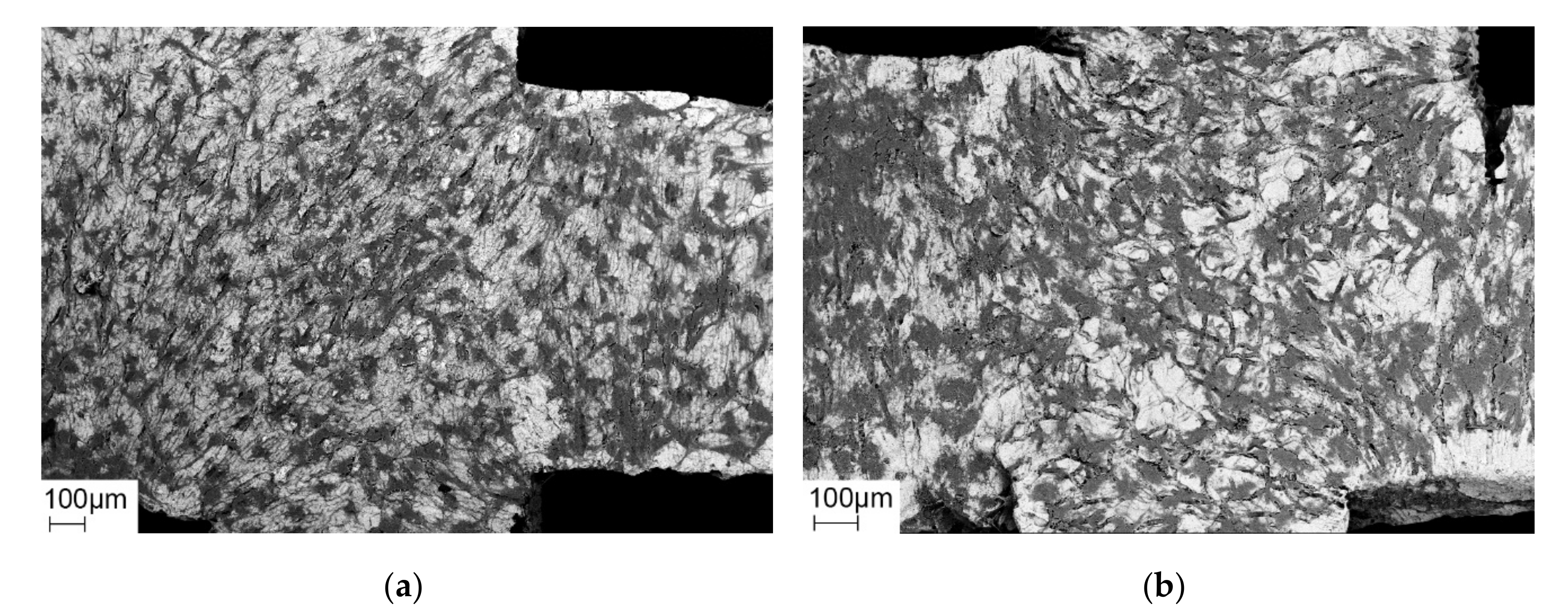
2.1. Cell Culture
2.1.1. Cell Adherence
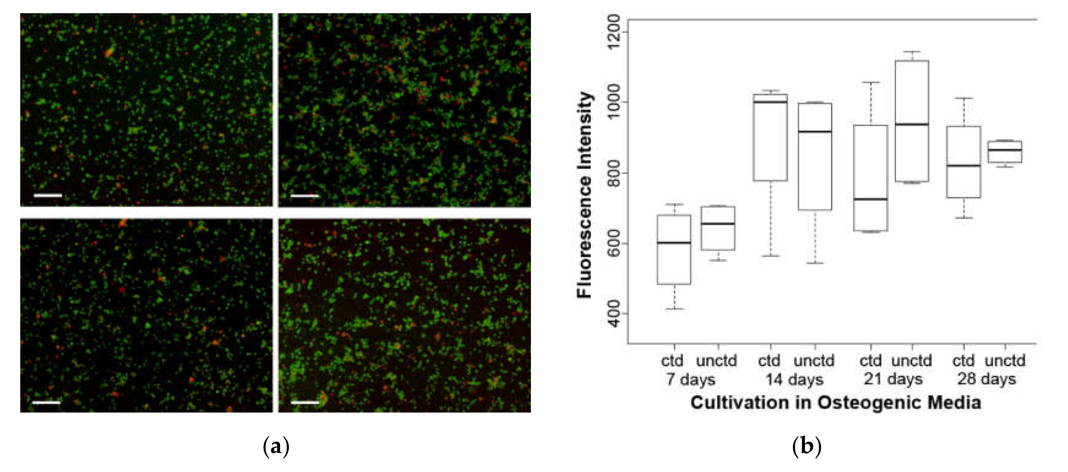
2.1.2. Proliferative Capability
2.1.3. Viability
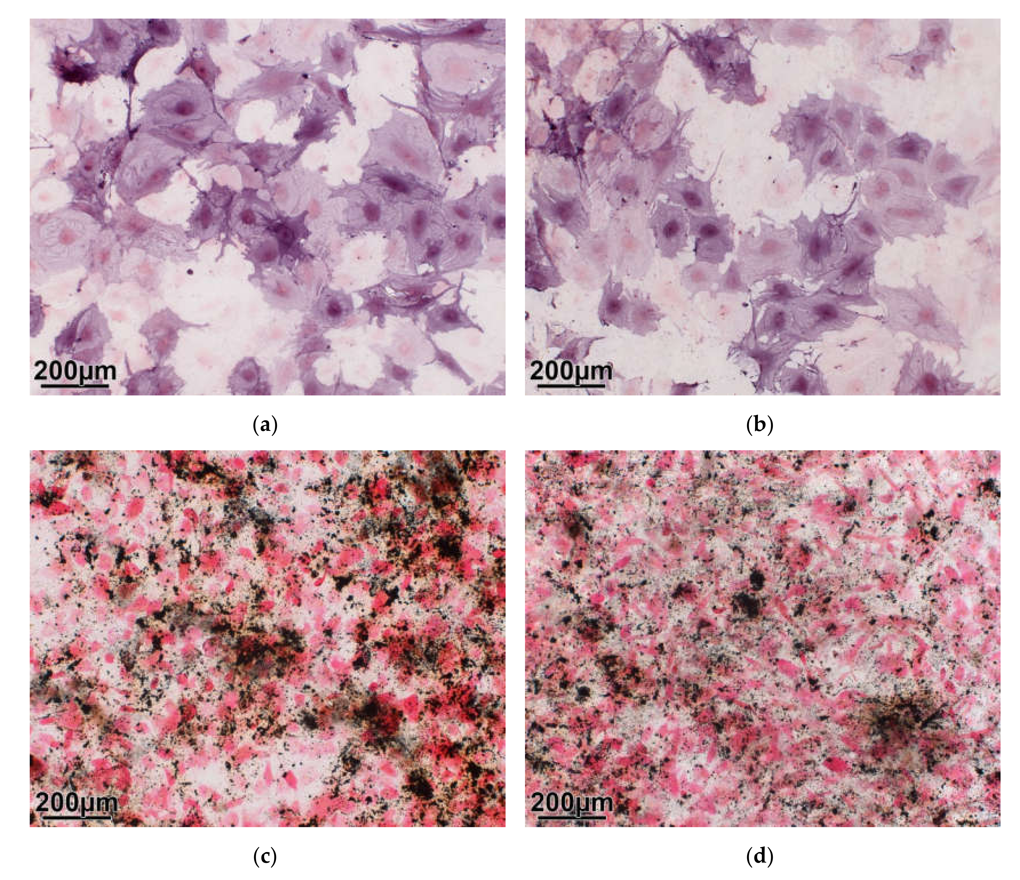
2.1.4. Osteogenic Differentiation
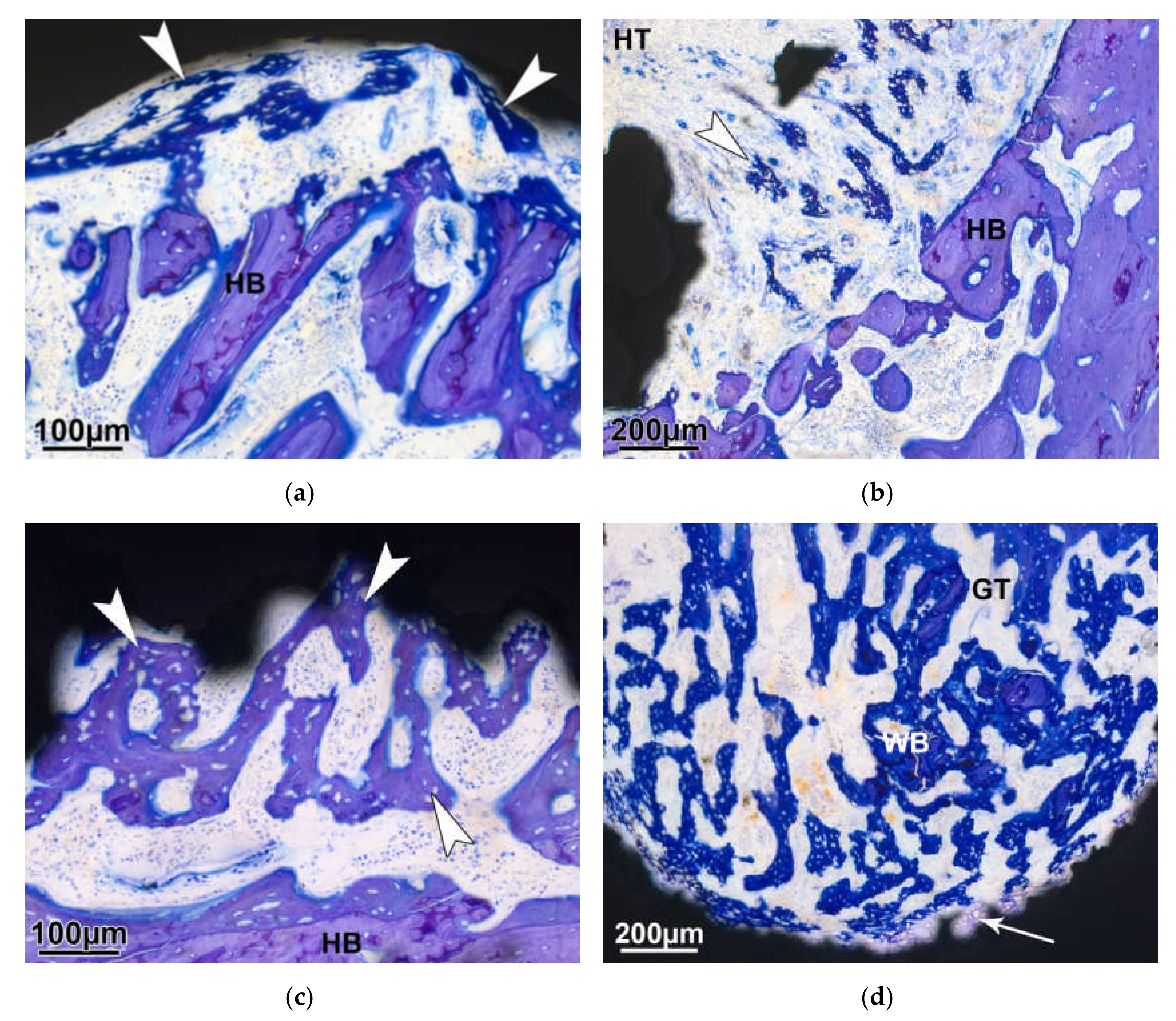
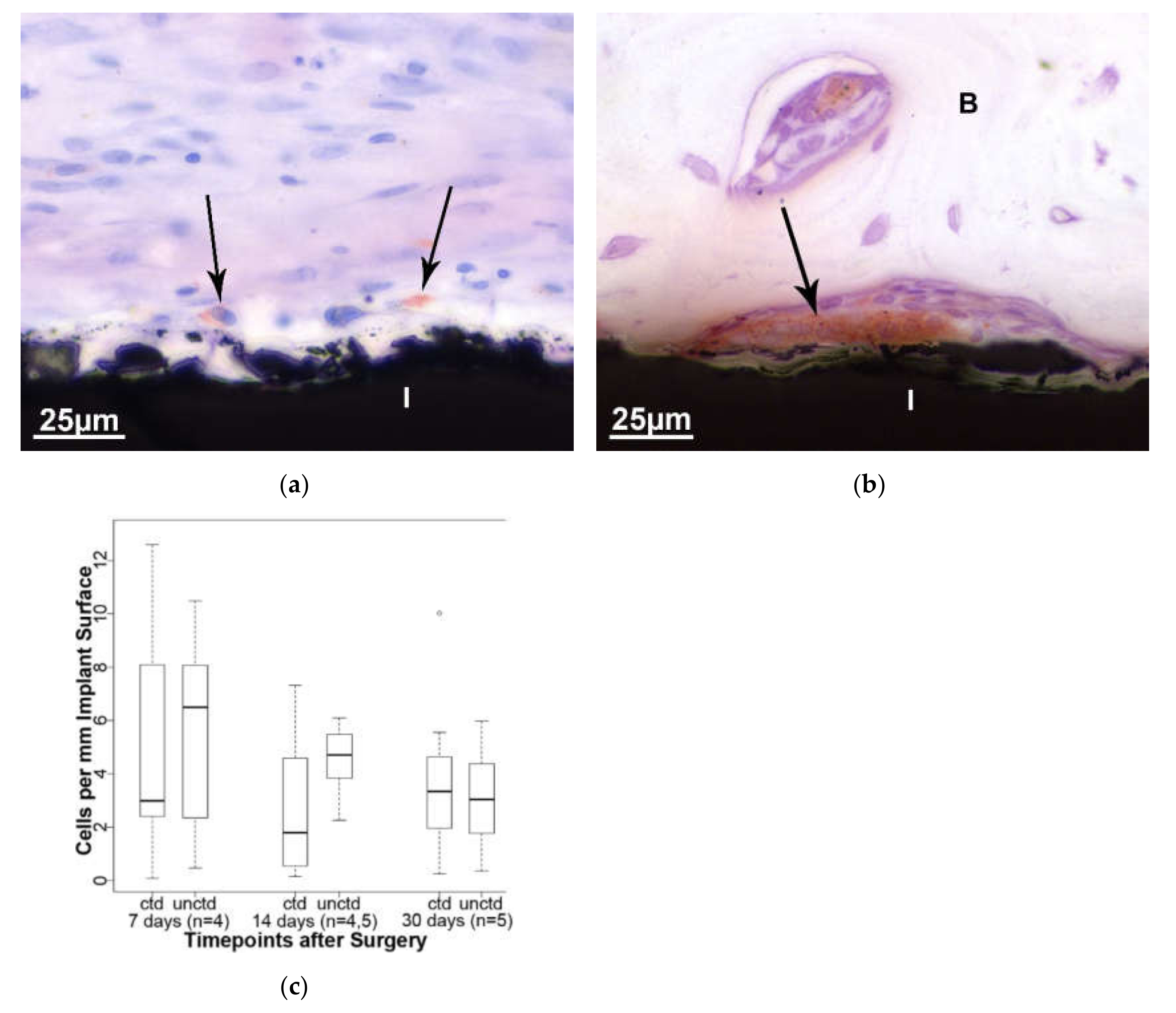
2.2. Small Animal Model
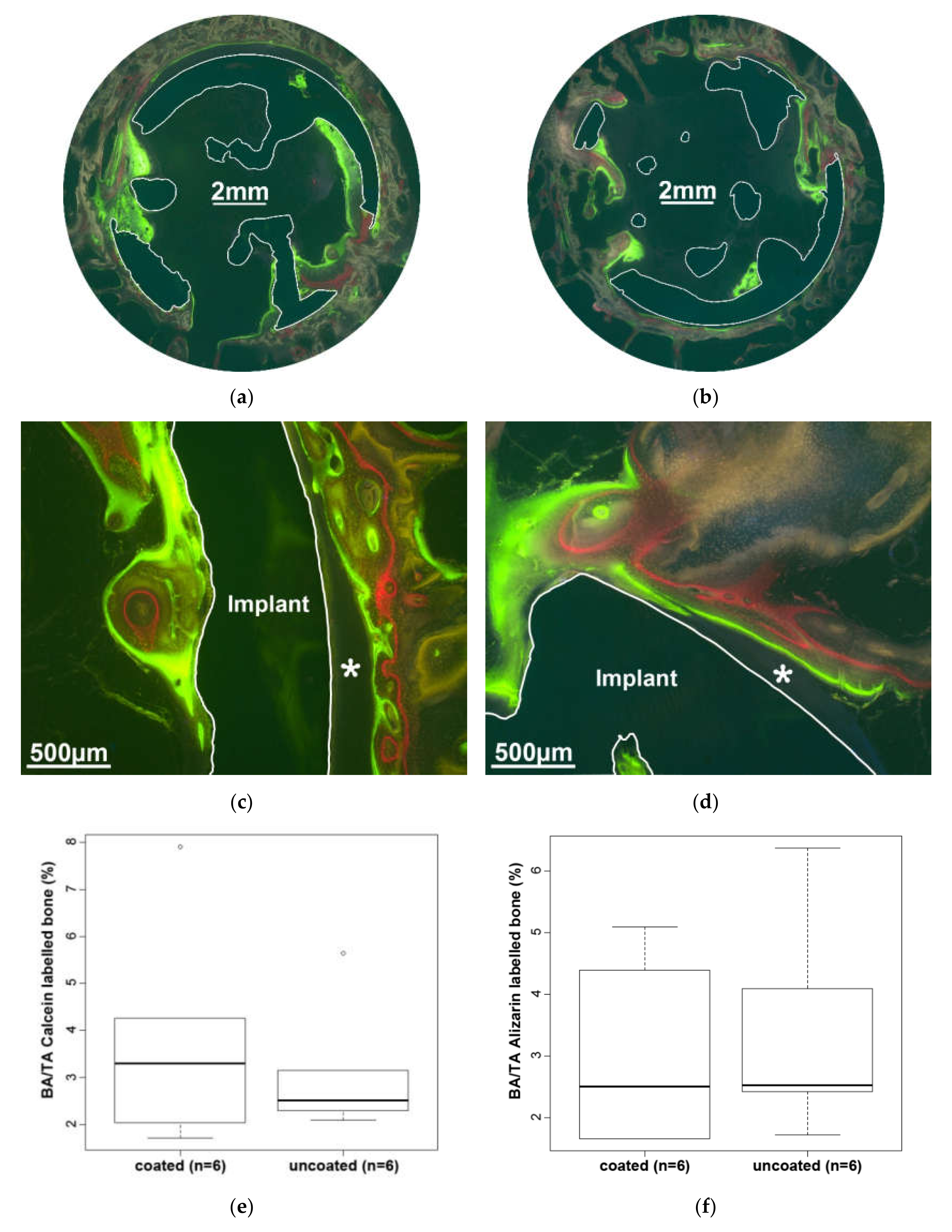
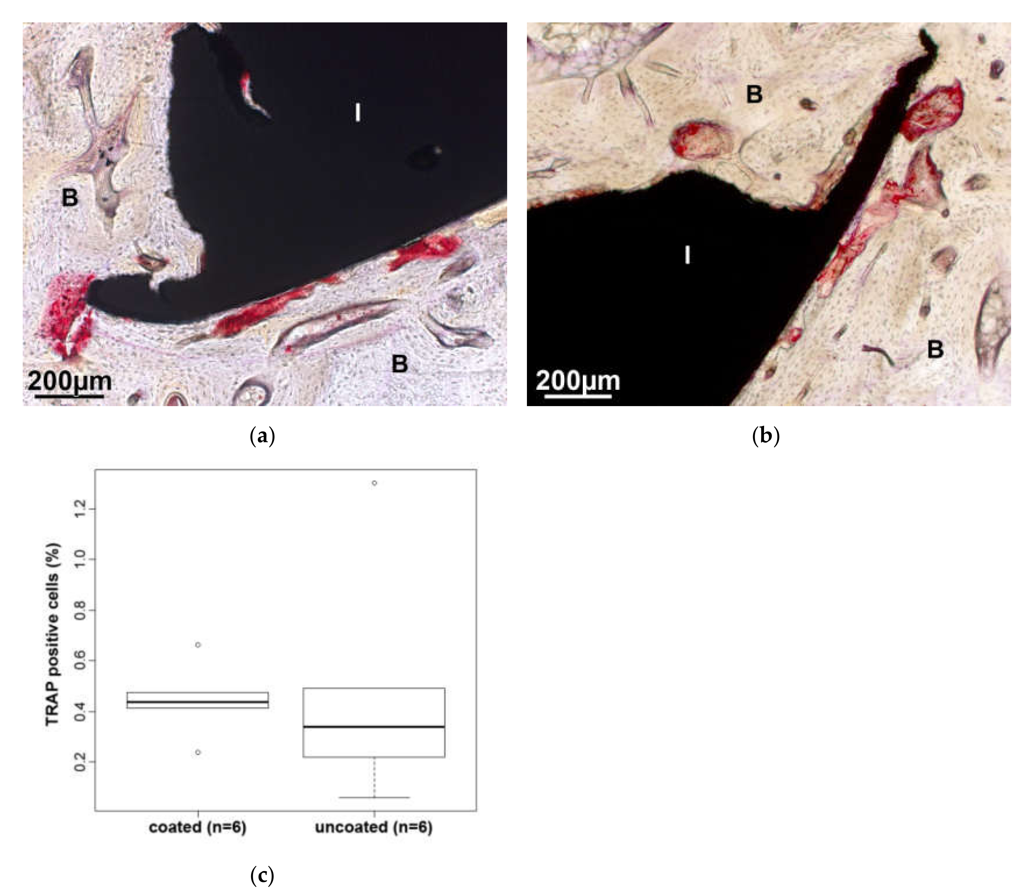
2.3. Large Animal Model
3. Discussion
4. Materials and Methods
4.1. Ethics Permissions
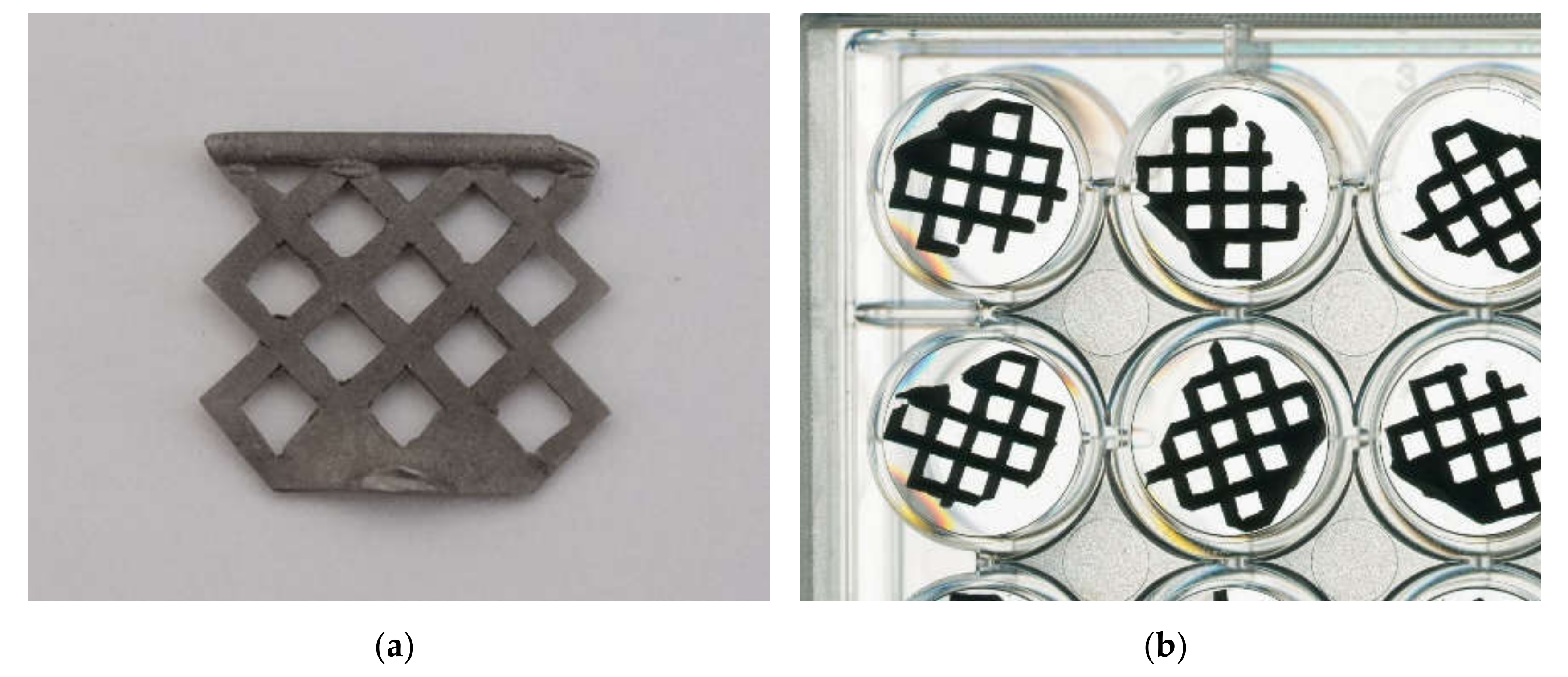
4.2. Material Used in Cell Culture and Animal Models
4.3. Cell Culture Experiments
4.3.1. Cell Adherence on the Material
4.3.2. Proliferative Capability of Adherent Cells
4.3.3. Viability of Cells
4.3.4. Osteogenic Differentiation
4.4. Animal Models
4.4.1. Small Animal Model (Rat)
Histology of Rat Femoral Condyles
Histomorphometry of Rat Femoral Condyles
4.4.2. Large Animal Model (Sheep)
Histology of Sheep Femoral Condyles
Histomorphometry of Sheep Femoral Condyles
4.5. Statistical Analysis
Author Contributions
Funding
Acknowledgments
Conflicts of Interest
References
- Einhorn, T.A.; Lee, C.A. Bone regeneration: New findings and potential clinical applications. J. Am. Acad. Orthop. Surg. 2001, 9, 157–165. [Google Scholar] [CrossRef] [PubMed]
- Einhorn, T.A. Enhancement of fracture-healing. J. Bone Joint Surg. Am. 1995, 77, 940–956. [Google Scholar] [CrossRef] [PubMed]
- Schnettler, R.; Stahl, J.; Alt, V.; Pavlidis, T.; Dingeldein, E.; Wenisch, S. Calcium Phosphate-Based Bone Substitutes. Eur. J. Trauma 2004, 30. [Google Scholar] [CrossRef]
- Wippermann, B.W.; Schratt, H.-E.; Steeg, S.; Tscherne, H. Komplikationen der Spongiosaentnahme am Beckenkamm Eine retrospektive Analyse von 1191 Fällen. Chirurg 1997, 68, 1286–1291. [Google Scholar] [CrossRef]
- Younger, E.M.; Chapman, M.W. Morbidity at bone graft donor sites. J. Orthop. Trauma 1989, 3, 192–195. [Google Scholar] [CrossRef] [Green Version]
- Journeaux, S.F.; Johnson, N.; Bryce, S.L.; Friedman, S.J.; Sommerville, S.M.; Morgan, D.A. Bacterial contamination rates during bone allograft retrieval. J. Arthroplast. 1999, 14, 677–681. [Google Scholar] [CrossRef]
- Cornell, C.N. Osteoconductive materials and their role as substitutes for autogenous bone grafts. Orthop. Clin. North Am. 1999, 30, 591–598. [Google Scholar] [CrossRef]
- Schnettler, R.; Dingeldein, E. Inorganic bone substitutes. In Tissue Engineering and Biodegradable Equivalents: Scientific and Clinical Applications; Lewandrowski, K.U., Wise, D.L., Trantolo, D.J., Gresser, J.D., Yaszemski, M.J., Altobelli, D.E., Eds.; Marcel Dekker Inc.: New York, NY, USA, 2002; pp. 401–432. ISBN 0824707559. [Google Scholar]
- Zhang, R.; Ma, P.X. Poly (α-hydroxyl acids)/hydroxyapatite porous composites for bone-tissue engineering. I. Preparation and morphology. J. Biomed. Mater. Res. 1999, 44, 446–455. [Google Scholar] [CrossRef]
- Hamadouche, M.; Sedel, L. Ceramics in orthopaedics. J. Bone Joint Surg. Br. Vol. 2000, 82, 1095–1099. [Google Scholar] [CrossRef] [PubMed]
- Hannouche, D.; Petite, H.; Sedel, L. Current trends in the enhancement of fracture healing. J. Bone Joint Surg. Br. Vol. 2001, 83, 157–164. [Google Scholar] [CrossRef] [PubMed]
- Jansen, J.A.; Von Recum, A.F.; Van Der Waerden, J.P.C.M.; De Groot, K. Soft tissue response to different types of sintered metal fibre-web materials. Biomaterials 1992, 13, 959–968. [Google Scholar] [CrossRef]
- Brunette, D.M.; Tengvall, P.; Textor, M.; Thomson, P. (Eds.) Titanium in Medicine: Materialscience, Surface Science, Engineering, Biological Responses and Medical Applications; Springer: Berlin, Germany, 2001; ISBN 3-540-66936-1. [Google Scholar]
- Li, L.-H.; Kim, H.-W.; Lee, S.-H.; Kong, Y.-M.; Kim, H.-E. Biocompatibility of titanium implants modified by microarc oxidation and hydroxyapatite coating. J. Biomed. Mater. Res. A 2005, 73, 48–54. [Google Scholar] [CrossRef]
- Jonasova, L.; Muller, F.A.; Helebrant, A.; Strnad, J.; Greil, P. Biomimetic apatite formation on chemically treated titanium. Biomaterials 2004, 25, 1187–1194. [Google Scholar] [CrossRef] [PubMed]
- Ishizawa, H.; Fujino, M.; Ogino, M. Mechanical and histological investigation of hydrothermally treated and untreated anodic titanium oxide films containing Ca and P. J. Biomed. Mater. Res. 1995, 29, 1459–1468. [Google Scholar] [CrossRef] [PubMed]
- Son, W.-w.; Zhu, X.; Shin, H.-i.; Ong, J.L.; Kim, K.-h. In vivo histological response to anodized and anodized/hydrothermally treated titanium implants. J. Biomed. Mater. Res. 2003, 66, 520–525. [Google Scholar] [CrossRef] [PubMed]
- Sul, Y.-T. The significance of the surface properties of oxidized titanium to the bone response: Special emphasis on potential biochemical bonding of oxidized titanium implant. Biomaterials 2003, 24, 3893–3907. [Google Scholar] [CrossRef]
- Sul, Y.T.; Johansson, C.B.; Jeong, Y.; Roser, K.; Wennerberg, A.; Albrektsson, T. Oxidized implants and their influence on the bone response. J. Mater. Sci. Mater. Med. 2001, 12, 1025–1031. [Google Scholar] [CrossRef]
- Li, L.-H.; Kong, Y.-M.; Kim, H.-W.; Kim, Y.-W.; Kim, H.-E.; Heo, S.-J.; Koak, J.-Y. Improved biological performance of Ti implants due to surface modification by micro-arc oxidation. Biomaterials 2004, 25, 2867–2875. [Google Scholar] [CrossRef]
- Nan, K.; Wang, Y.; Chen, X.; Ning, C.; Wang, L.; Zhao, N. Application research of plasma-enhanced electrochemical surface ceramic-coating technology on titanium implants. J. Biomed. Mater. Res. 2005, 75, 328–333. [Google Scholar] [CrossRef]
- Clemens, J.A.; Klein, C.P.; Vriesde, R.C.; Rozing, P.M.; de Groot, K. Healing of large (2 mm) gaps around calcium phosphate-coated bone implants: A study in goats with a follow-up of 6 months. J. Biomed. Mater. Res. 1998, 40, 341–349. [Google Scholar] [CrossRef]
- Vehof, J.W.; Mahmood, J.; Takita, H.; van’t Hof, M.A.; Kuboki, Y.; Spauwen, P.H.; Jansen, J.A. Ectopic bone formation in titanium mesh loaded with bone morphogenetic protein and coated with calcium phosphate. Plast. Reconstr. Surg. 2001, 108, 434–443. [Google Scholar] [CrossRef] [PubMed]
- Vehof, J.W.M.; van den Dolder, J.; de Ruijter, J.E.; Spauwen, P.H.M.; Jansen, J.A. Bone formation in CaP-coated and noncoated titanium fiber mesh. J. Biomed. Mater. Res. A 2003, 64, 417–426. [Google Scholar] [CrossRef] [PubMed]
- Gan, L.; Wang, J.; Tache, A.; Valiquette, N.; Deporter, D.; Pilliar, R. Calcium phosphate sol-gel-derived thin films on porous-surfaced implants for enhanced osteoconductivity. Part II: Short-term in vivo studies. Biomaterials 2004, 25, 5313–5321. [Google Scholar] [CrossRef] [PubMed]
- Kim, H.-W.; Koh, Y.-H.; Li, L.-H.; Lee, S.; Kim, H.-E. Hydroxyapatite coating on titanium substrate with titania buffer layer processed by sol-gel method. Biomaterials 2004, 25, 2533–2538. [Google Scholar] [CrossRef]
- Kim, H.-W.; Kim, H.-E.; Knowles, J.C. Fluor-hydroxyapatite sol-gel coating on titanium substrate for hard tissue implants. Biomaterials 2004, 25, 3351–3358. [Google Scholar] [CrossRef]
- Nguyen, H.Q.; Deporter, D.A.; Pilliar, R.M.; Valiquette, N.; Yakubovich, R. The effect of sol-gel-formed calcium phosphate coatings on bone ingrowth and osteoconductivity of porous-surfaced Ti alloy implants. Biomaterials 2004, 25, 865–876. [Google Scholar] [CrossRef]
- Lacefiled, W.R. Hydroxyapatite coatings. In An Introduction to Bioceramics; Hench, L.L., Wilson, J., Eds.; World Scientific Publishing Co.: Singapore, 1993. [Google Scholar]
- Hench, L.L. Bioceramics. J. Am. Ceram. Soc. 1998, 81, 1705–17028. [Google Scholar] [CrossRef]
- Hanawa, T.; Nodasaka, Y.; Ukai, H.; Murakami, K.; Asaoka, K. Compatibility of MC3T3-E1 cells calcium-ion-implanted titanium. J. Jpn. Soc. Biomater. 1994, 12, 209–216. [Google Scholar]
- Hanawa, T.; Kamiura, Y.; Yamamoto, S.; Kohgo, T.; Amemiya, A.; Ukai, H.; Murakami, K.; Asaoka, K. Early bone formation around calcium-ion-implanted titanium inserted into rat tibia. J. Biomed. Mater. Res. 1997, 36, 131–136. [Google Scholar] [CrossRef]
- Ariji, H.; Nakade, O.; Koyama, H.; Takada, J.; Kaku, T. Effects of Extracellular Calcium on the Proliferation, Differentiation and Gene Expressions of Bone Morphogenetic Proteins-2 an -4 in Human Gingiva-Derived Fibroblasts. Jpn. J. Oral Biol. 2000, 42, 49–55. [Google Scholar] [CrossRef] [Green Version]
- Nakade, O.; Takahashi, K.; Taishin, T.; Aoki, T.; Kaku, T. Effect of extracellular calcium on the gene expression of bone morphogenetic protein-2 and -4 of normal human bone cells. J. Bone Miner. Metab. 2001, 19, 13–19. [Google Scholar] [CrossRef] [PubMed]
- Wang, W.; Yeung, K.W.K. Bone grafts and biomaterials substitutes for bone defect repair: A review. Bioact. Mater. 2017, 2, 224–247. [Google Scholar] [CrossRef] [PubMed]
- Dimitriou, R.; Mataliotakis, G.I.; Angoules, A.G.; Kanakaris, N.K.; Giannoudis, P.V. Complications following autologous bone graft harvesting from the iliac crest and using the RIA: A systematic review. Injury 2011, 42, S3–S15. [Google Scholar] [CrossRef] [PubMed]
- Arrington, E.D.; Smith, W.J.; Chambers, H.G.; Bucknell, A.L.; Davino, N.A. Complications of iliac crest bone graft harvesting. Clin. Orthop. Relat. Res. 1996, 300–309. [Google Scholar] [CrossRef] [PubMed]
- Kawahara, H. Biological requirements for biomaterials. I. Cytotoxicity of biomaterials, in vitro. II. Cell adhesion to biomaterials, in vitro. Implantologist 1985, 3, 41–49. [Google Scholar] [PubMed]
- Brånemark, P.I.; Hansson, B.O.; Adell, R.; Breine, U.; Lindström, J.; Hallén, O.; Ohman, A. Osseointegrated implants in the treatment of the edentulous jaw. Experience from a 10-year period. Scand. J. Plast. Reconstr. Surg. Suppl. 1977, 16, 1–132. [Google Scholar] [PubMed]
- Brånemark, P.-I.; Zarb, G.A. Tissue integrated protheses: Osteointegration in clinical dentistry. In Tissue-Integrated Prostheses: Osseointegration in Clinical Dentistry; Albrektsson, T., Ed.; Quintessence Publishing Co Inc.: Chicago, IL, USA, 2008; pp. 11–76. ISBN 978-0867151299. [Google Scholar]
- Tyliszczak, B.; Gaca, K.Z.; Sobczak-Kupiec, A.; Dulian, P. Mechanochemical synthesis and investigations of calcium titanate powders and their acrylic dispersions. J. Eur. Ceram. Soc. 2014, 34, 2259–2264. [Google Scholar] [CrossRef]
- Blokhuis, T.J.; Termaat, M.F.; den Boer, F.C.; Patka, P.; Bakker, F.C.; Haarman, H.J. Properties of calcium phosphate ceramics in relation to their in vivo behavior. J. Trauma 2000, 48, 179–186. [Google Scholar] [CrossRef]
- Texhammar, R.; Colton, C.L.; Baumgart, F. AO/ASIF Instruments and Implants. A Technical Manual, 2nd ed.; Compl. rev. and enl.; Springer: Berlin, Germany, 1994; ISBN 9780387568959. [Google Scholar]
- Wang, K. The use of titanium for medical applications in the USA. Mater. Sci. Eng. A 1996, 213, 134–137. [Google Scholar] [CrossRef]
- Frosch, K.-H.; Sondergeld, I.; Dresing, K.; Rudy, T.; Lohmann, C.H.; Rabba, J.; Breme, J.; Stürmer, K.M. Beschleunigung der Osseointegration von Titanimplantaten durch Besiedelung mit pluripotenten, mesenchymalen Vorläuferzellen. In Chirurgisches Forum 2002; Siewert, J.R., Neugebauer, E., Hartel, W., Menger, M.D., Eds.; Springer: Berlin/Heidelberg, Germany, 2002; pp. 453–455. ISBN 978-3-540-43300-2. [Google Scholar]
- Long, M.; Rack, H.J. Titanium alloys in total joint replacement—A materials science perspective. Biomaterials 1998, 19, 1621–1639. [Google Scholar] [CrossRef]
- Kasemo, B. Biocompatibility of titanium implants: Surface science aspects. J. Prosthet. Dent. 1983, 49, 832–837. [Google Scholar] [CrossRef]
- Kasemo, B.; Lausmaa, J. Biomaterial and implant surfaces: A surface science approach. Int. J. Oral Maxillofac. Implants 1988, 3, 247–259. [Google Scholar] [PubMed]
- Elias, C.N.; Lima, J.H.C.; Valiev, R.; Meyers, M.A. Biomedical applications of titanium and its alloys. JOM 2008, 60, 46–49. [Google Scholar] [CrossRef]
- Sidambe, A.T. Biocompatibility of Advanced Manufactured Titanium Implants-A Review. Materials (Basel) 2014, 7, 8168–8188. [Google Scholar] [CrossRef] [PubMed] [Green Version]
- Niinomi, M.; Hattori, T.; Niwa, S. Material Characteristics and Biocompatibility of Low Ridigity Titanium Alloys for Biomedical Applications. In Biomaterials in Orthopaedics; Yaszemski, M.J., Trantolo, D.J., Lewandrowski, K.U., Hairci, V., Altobelli, D.E., Wise, D.L., Eds.; Marcel Dekker Inc.: New York, NY, USA, 2003; pp. 41–62. [Google Scholar]
- Challa, V.S.A.; Mali, S.; Misra, R.D.K. Reduced toxicity and superior cellular response of preosteoblasts to Ti-6Al-7Nb alloy and comparison with Ti-6Al-4V. J. Biomed. Mater. Res. A 2013, 101, 2083–2089. [Google Scholar] [CrossRef]
- Hanks, C.T.; Wataha, J.C.; Sun, Z. In vitro models of biocompatibility: A review. Dent. Mater. 1996, 12, 186–193. [Google Scholar] [CrossRef]
- Gomes, P.S.; Fernandes, M.H. Rodent models in bone-related research: The relevance of calvarial defects in the assessment of bone regeneration strategies. Lab. Anim. 2011, 45, 14–24. [Google Scholar] [CrossRef]
- Hardouin, P.; Chopin, D.; DeVyver, B.; Flautre, B.; Blary, M.C.; Guigui, P.; Anselme, K. Quantitative histomorphometric evaluation of spinal arthrodesis after biphasic calcium phosphate ceramic implantation in sheep. J. Mater. Sci. Mater. Med. 1992, 3, 212–218. [Google Scholar] [CrossRef]
- Kessler, S.; Mayr-Wohlfart, U.; Ignatius, A.; Puhl, W.; Claes, L.; Günther, K.P. Histomorphological, histomorphometrical and biomechanical analysis of ceramic bone substitutes in a weight-bearing animal model. J. Mater. Sci. Mater. Med. 2002, 13, 191–195. [Google Scholar] [CrossRef]
- Blattert, T.R.; Delling, G.; Weckbach, A. Evaluation of an injectable calcium phosphate cement as an autograft substitute for transpedicular lumbar interbody fusion: A controlled, prospective study in the sheep model. Eur. Spine J. 2003, 12, 216–223. [Google Scholar] [CrossRef] [Green Version]
- Le Nihouannen, D.; Saffarzadeh, A.; Gauthier, O.; Moreau, F.; Pilet, P.; Spaethe, R.; Layrolle, P.; Daculsi, G. Bone tissue formation in sheep muscles induced by a biphasic calcium phosphate ceramic and fibrin glue composite. J. Mater. Sci. Mater. Med. 2008, 19, 667–675. [Google Scholar] [CrossRef] [PubMed]
- Olivares-Navarrete, R.; Gittens, R.A.; Schneider, J.M.; Hyzy, S.L.; Haithcock, D.A.; Ullrich, P.F.; Schwartz, Z.; Boyan, B.D. Osteoblasts exhibit a more differentiated phenotype and increased bone morphogenetic protein production on titanium alloy substrates than on poly-ether-ether-ketone. Spine J. 2012, 12, 265–272. [Google Scholar] [CrossRef] [PubMed] [Green Version]
- Zhao, G.; Schwartz, Z.; Wieland, M.; Rupp, F.; Geis-Gerstorfer, J.; Cochran, D.L.; Boyan, B.D. High surface energy enhances cell response to titanium substrate microstructure. J. Biomed. Mater. Res. A 2005, 74, 49–58. [Google Scholar] [CrossRef] [PubMed]
- Wilkinson, A.; Hewitt, R.N.; McNamara, L.E.; McCloy, D.; Dominic Meek, R.M.; Dalby, M.J. Biomimetic microtopography to enhance osteogenesis in vitro. Acta Biomater. 2011, 7, 2919–2925. [Google Scholar] [CrossRef]
- Lincks, J.; Boyan, B.D.; Blanchard, C.R.; Lohmann, C.H.; Liu, Y.; Cochran, D.L.; Dean, D.D.; Schwartz, Z. Response of MG63 osteoblast-like cells to titanium and titanium alloy is dependent on surface roughness and composition. Biomaterials 1998, 19, 2219–2232. [Google Scholar] [CrossRef]
- Chehroudi, B.; Ghrebi, S.; Murakami, H.; Waterfield, J.D.; Owen, G.; Brunette, D.M. Bone formation on rough, but not polished, subcutaneously implanted Ti surfaces is preceded by macrophage accumulation. J. Biomed. Mater. Res. A 2010, 93, 724–737. [Google Scholar] [CrossRef]
- Deligianni, D.D.; Katsala, N.; Ladas, S.; Sotiropoulou, D.; Amedee, J.; Missirlis, Y.F. Effect of surface roughness of the titanium alloy Ti-6Al-4V on human bone marrow cell response and on protein adsorption. Biomaterials 2001, 22, 1241–1251. [Google Scholar] [CrossRef]
- Conner, K.A.; Sabatini, R.; Mealey, B.L.; Takacs, V.J.; Mills, M.P.; Cochran, D.L. Guided bone regeneration around titanium plasma-sprayed, acid-etched, and hydroxyapatite-coated implants in the canine model. J. Periodontol. 2003, 74, 658–668. [Google Scholar] [CrossRef]
- Sullivan, D.Y.; Sherwood, R.L.; Mai, T.N. Preliminary results of a multicenter study evaluating a chemically enhanced surface for machined commercially pure titanium implants. J. Prosthet. Dent. 1997, 78, 379–386. [Google Scholar] [CrossRef]
- Predecki, P.; Stephan, J.E.; Auslaender, B.A.; Mooney, V.L.; Kirkland, K. Kinetics of bone growth into cylindrical channels in aluminum oxide and titanium. J. Biomed. Mater. Res. 1972, 6, 375–400. [Google Scholar] [CrossRef]
- Epple, M. Biomaterialien und Biomineralisation; Vieweg + Teubner: Wiesbaden, Germany, 2003; ISBN 978-3-519-00354-0. [Google Scholar]
- Ohtsu, N.; Sato, K.; Yanagawa, A.; Saito, K.; Imai, Y.; Kohgo, T.; Yokoyama, A.; Asami, K.; Hanawa, T. CaTiO(3) coating on titanium for biomaterial application—Optimum thickness and tissue response. J. Biomed. Mater. Res. A 2007, 82, 304–315. [Google Scholar] [CrossRef] [PubMed]
- Hanisch, O.; Cortella, C.A.; Boskovic, M.M.; James, R.A.; Slots, J.; Wikesjo, U.M. Experimental peri-implant tissue breakdown around hydroxyapatite-coated implants. J. Periodontol. 1997, 68, 59–66. [Google Scholar] [CrossRef] [PubMed]
- Albrektsson, T. Hydroxyapatite-coated implants: A case against their use. J. Oral Maxillofac. Surg. 1998, 56, 1312–1326. [Google Scholar] [CrossRef]
- Morscher, E.W.; Hefti, A.; Aebi, U. Severe osteolysis after third-body wear due to hydroxyapatite particles from acetabular cup coating. J. Bone Joint Surg. Br. Vol. 1998, 80, 267–272. [Google Scholar] [CrossRef] [PubMed]
- Suh, J.-Y.; Jeung, O.-C.; Choi, B.-J.; Park, J.-W. Effects of a novel calcium titanate coating on the osseointegration of blasted endosseous implants in rabbit tibiae. Clin. Oral Implants Res. 2007, 18, 362–369. [Google Scholar] [CrossRef]
- Nebe, J.B.; Muller, L.; Luthen, F.; Ewald, A.; Bergemann, C.; Conforto, E.; Muller, F.A. Osteoblast response to biomimetically altered titanium surfaces. Acta Biomater. 2008, 4, 1985–1995. [Google Scholar] [CrossRef]
- Nayab, S.N.; Jones, F.H.; Olsen, I. Effects of calcium ion implantation on human bone cell interaction with titanium. Biomaterials 2005, 26, 4717–4727. [Google Scholar] [CrossRef]
- Webster, T.J.; Ergun, C.; Doremus, R.H.; Lanford, W.A. Increased osteoblast adhesion on titanium-coated hydroxylapatite that forms CaTiO3. J. Biomed. Mater. Res. A 2003, 67, 975–980. [Google Scholar] [CrossRef]
- Zhu, Y.; Wang, X.; Zhou, Y.; Zhao, C.; Yuan, J.; Wu, Z.; Wu, S.; Wang, S. In situ formation of bioactive calcium titanate coatings on titanium screws for medical implants. RSC Adv. 2016, 6, 53182–53187. [Google Scholar] [CrossRef]
- Wang, Z.-L.; He, R.-Z.; Tu, B.; Cao, X.; He, J.-S.; Xia, H.-S.; Liang, C.; Zou, M.; Wu, S.; Wu, Z.-J.; et al. Enhanced biocompatibility and osseointegration of calcium titanate coating on titanium screws in rabbit femur. J. Huazhong Univ. Sci. Technol. Med. Sci. 2017, 37, 362–370. [Google Scholar] [CrossRef]
- Guillén Giron, T.; Ohrndorf, A.; Christ, H.-J. Biomechanical Evaluation of the Osseointegration of Biologiecally Coated Open-Cell Titanium Implants. In Proceedings of the 13th International Conference on Fracture, Bejing, China, 16–21 June 2013; Available online: https://www.researchgate.net/publication/248705708_Characterisation_of_a_metallic_foam-cement_composite_under_selected_loading_conditions (accessed on 3 March 2020).
- Guillén Girón, T. Properties and Application Spectrum of Cast Porous Implants Made of Ti-6Al-7Nb in Coated and Uncoated Conditions. Ph.D. Thesis, University of Siegen, Siegen, Germany, 2012. [Google Scholar]
- Barik, A.; Chakravorty, N. Targeted Drug Delivery from Titanium Implants: A Review of Challenges and Approaches. In Trends in Biomedical Research; Pokorski, M., Ed.; Springer International Publishing: Cham, Switzerland, 2020; pp. 1–17. ISBN 978-3-030-41218-0. [Google Scholar]
- Raina, D.B.; Larsson, D.; Sezgin, E.A.; Isaksson, H.; Tägil, M.; Lidgren, L. Biomodulation of an implant for enhanced bone-implant anchorage. Acta Biomater. 2019, 96, 619–630. [Google Scholar] [CrossRef] [PubMed]
- Bai, H.; Zhao, Y.; Wang, C.; Wang, Z.; Wang, J.; Liu, H.; Feng, Y.; Lin, Q.; Li, Z.; Liu, H. Enhanced osseointegration of three-dimensional supramolecular bioactive interface through osteoporotic microenvironment regulation. Theranostics 2020, 10, 4779–4794. [Google Scholar] [CrossRef] [PubMed]
- Hashemi, A.; Ezati, M.; Mohammadnejad, J.; Houshmand, B.; Faghihi, S. Chitosan Coating of TiO2 Nanotube Arrays for Improved Metformin Release and Osteoblast Differentiation. Int. J. Nanomed. 2020, 15, 4471–4481. [Google Scholar] [CrossRef] [PubMed]
- Wu, F.; Xu, J.; Yan, R.; Hu, B.; Li, G.; Jin, M.; Jiang, X.; Li, J.; Tang, P.; Zhu, J.; et al. In vitro and in vivo evaluation of antibacterial activity of polyhexamethylene guanidine (PHMG)-loaded TiO(2) nanotubes. Biomed. Mater. 2020, 15, 45016. [Google Scholar] [CrossRef] [PubMed]
- Hagemann, K. Gießtechnische Herstellung Offenporiger Implantate aus Ti6Al7Nb. Ph.D. Thesis, RWTH Aachen University, Aachen, Germany, 2012. [Google Scholar]
- Wenisch, S.; Trinkaus, K.; Hild, A.; Hose, D.; Herde, K.; Heiss, C.; Kilian, O.; Alt, V.; Schnettler, R. Human reaming debris: A source of multipotent stem cells. Bone 2005, 36, 74–83. [Google Scholar] [CrossRef] [PubMed]
- Donath, K.; Breuner, G. A method for the study of undecalcified bones and teeth with attached soft tissues*. The Sage-Schliff (sawing and grinding) Technique. J. Oral Pathol. Med. 1982, 11, 318–326. [Google Scholar] [CrossRef]
Sample Availability: Samples of the compounds are not available from the authors. |


| Time Point | Histology | |
|---|---|---|
| Coated | Uncoated | |
| 7 days | 5 | 4 * |
| 14 days | 5 | 5 |
| 30 days | 6 | 5 ** |
© 2020 by the authors. Licensee MDPI, Basel, Switzerland. This article is an open access article distributed under the terms and conditions of the Creative Commons Attribution (CC BY) license (http://creativecommons.org/licenses/by/4.0/).
Share and Cite
Sommer, U.; Laurich, S.; de Azevedo, L.; Viehoff, K.; Wenisch, S.; Thormann, U.; Alt, V.; Heiss, C.; Schnettler, R. In Vitro and In Vivo Biocompatibility Studies of a Cast and Coated Titanium Alloy. Molecules 2020, 25, 3399. https://doi.org/10.3390/molecules25153399
Sommer U, Laurich S, de Azevedo L, Viehoff K, Wenisch S, Thormann U, Alt V, Heiss C, Schnettler R. In Vitro and In Vivo Biocompatibility Studies of a Cast and Coated Titanium Alloy. Molecules. 2020; 25(15):3399. https://doi.org/10.3390/molecules25153399
Chicago/Turabian StyleSommer, Ursula, Stephan Laurich, Lucie de Azevedo, Katharina Viehoff, Sabine Wenisch, Ulrich Thormann, Volker Alt, Christian Heiss, and Reinhard Schnettler. 2020. "In Vitro and In Vivo Biocompatibility Studies of a Cast and Coated Titanium Alloy" Molecules 25, no. 15: 3399. https://doi.org/10.3390/molecules25153399