1. Introduction
Redox-flow batteries (RFBs) are promising electrochemical energy storage devices for mitigating the intermittent fluctuation of solar and wind power plants [
1,
2]. These batteries offer several advantages, such as independent sizing of power and energy, room temperature operation, scalability, long charge/discharge cycle life and high efficiency [
3]. Over the years, various types of RFBs, such as vanadium-based RFBs [
4,
5,
6] and metal–air flow batteries have been developed [
7,
8,
9]. Particularly, Zn–air battery presents a high potential for mobile and stationary applications because of its high theoretical energy density (1087 Wh kg
−1, oxygen inclusive), abundant raw materials, environmental friendliness and economic viability [
10,
11,
12,
13]. To improve its cycling and discharge performance, various studies have mainly focused on preparation and improvement of Zn electrode [
14,
15,
16], electrocatalyst air electrodes [
17,
18] and electrolyte formulations [
7,
19].
In such batteries, the Zn electrode can be a semi-solid, fluidic electrode, in which particles are mixed into the electrolyte to form a slurry [
9]. In other words, the Zn slurry (Zn particles suspended in alkaline electrolytes) is used as both the anode electrode and electrolyte [
20,
21]. In these batteries, unlike conventional Zn–air batteries, the volume of tank or the amount/concentration of Zn particles in the slurry, rather than the size of the porous Zn electrode used in the system, determine the capacity of the battery [
22,
23]. Moreover, such Zn slurry-based configuration is believed to minimize formation of dendrites and surface passivation since the negative electrode acts only as a current collector [
9,
23,
24,
25], thus enhance battery performance.
However, some issues, such as full utilization of the Zn particles in the electrochemical reaction, blockage of the Zn particles in the electrode [
9], integral battery configuration [
26] and appropriate membrane development [
27,
28] have been impeding the development and commercialization of rechargeable Zn slurry–air flow batteries.
The membrane is used for OH
− ion conduction and avoiding mixing of the positive and negative active materials. To achieve this, membrane with high alkaline stability, OH
− conductivity, mechanical stability and low/no crossover of zincate (Zn(OH)
42−) ions is required. The overall performance and economic viability of this battery are greatly affected by the properties of the membrane employed [
27]. Commercial Zn–air batteries usually use porous polyolefin-based membranes. An excellent review on porous membranes for batteries has been published [
29]. One of the disadvantages of these types of porous membranes in RFBs is the crossover active species [
30]. Thus, in Zn–air batteries, the soluble Zn(OH)
42− ion can pass through the membranes to the air electrode, where the Zn(OH)
42− can be converted to ZnO, depending on the pH, (Zn(OH)
42− → ZnO (s) + H
2O + 2OH
−). The formation of ZnO layers has been reported to cause loss of battery capacity [
31] and large cell polarization [
11] (as the ZnO powers clog the porous air electrode). Therefore, there is a need for minimizing the crossover of Zn(OH)
42− ions through the membranes by optimizing their porosity, pore size and pore size distribution.
To address this issue, the use of anion exchange membranes (AEMs) [
27,
31,
32,
33], inorganic-filling [
34] or polymer-coating of porous membranes [
35,
36] have been proposed. For the former, the development of alkaline stable AEMs with well-defined and controlled ionic channel size to improve its selectivity without reducing the ionic conductivity is required. Abbasi et al. [
31] prepared benzylic quaternized AEMs using poly (2,6-dimethyl-1,4-phenylene oxide) (PPO) and trimethylamine (TMA) and investigated its Zn–air battery discharge performance (specific discharge capacity of ~800 mAh g
−1Zn). The PPO–TMA membrane exhibited a low Zn(OH)
42− diffusion coefficient of 1.1 × 10
−8 cm
2 min
−1.
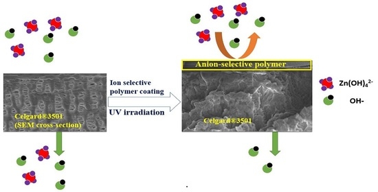
Another promising strategy, which is rarely used in Zn–air batteries, is surface modification of porous membranes. One way to achieve this is to coat a thin ion-selective polymer layer. The coat is expected to allow OH
− transfer through the membrane and minimizes the migration of Zn(OH)
42− ions to the cathode compartment without significantly affecting the ion conductivity. Coating of Celgard
® membranes with Nafion
® 117 solution [
35] and polymerized ionic liquid [
36] have been reported in the literature. Other than these two studies, the method remains to be not explored and not tested in membranes for Zn slurry–air flow batteries. Moreover, mostly polypropylene (PP)-based Celgard
® membranes have been explored, while other commercial porous membranes performance in such batteries remain to be not well studied.
The objectives of the present work were to (i) investigate the performance of several commercial membranes in Zn slurry–air flow battery and screen out appropriate membrane for the application, and (ii) coat the porous membranes with anion-exchange polymers to improve their selectivity. First, six commercial membranes were ex situ characterized in terms of electrolyte uptake, ion conductivity and Zn(OH)
42− ions crossover and then tested in a 25 cm
2 Zn slurry–air flow battery. Aiming at decreasing the crossover of Zn(OH)
42− ions, Celgard
® 3501 membrane was modified with two different anion exchange polymers. A solution of quaternized PPO and
N,
N-diallylpiperidinium chloride (DAPCl) was cast on the top surface of the porous membrane and cross-linked via UV irradiation in the presence of a photo-initiator. Moreover, a commercial anion exchange ionomer, Fumion FAA-3-SOLUT-10 (Fumatech, Germany) was used to modify the same support membrane for comparison purpose. DAPCl was chosen because of its high alkaline stability [
37,
38]. Similar UV irradiation technique for coating
N-spirocyclic quaternary ammonium monomer-based ionomer on Tetratex
®PTFE porous substrate has been reported recently elsewhere [
39].
3. Materials and Methods
3.1. Materials
PPO (Mn 20,000 and Polydispersity ~2.5) was purchased from Polysciences, Inc. Chlorobenzene (ACS reagent, ≥99.5%), N-methyl-2-pyrrolidone (NMP, reagent grade), tetrahydrofuran (THF, ACS, >99%), diethyl ether (>99%), 1,2-dichloroethane (99.8%), allyl bromide (98%), allyl chloride (98%) and chloroform (99.8%) were purchased from Alfa Aesar (Thermo Fisher, Kandel, Germany). Diallymethylamine (97%) and piperidine (≥99%) were bought from ABCR GmbH (Karlsruhe, Germany). Dimethyl sulfoxide-d6 (DMSO-d6, 99.9%) was supplied from Acros Organics ((Thermo Fisher, Kandel, Germany). N-bromosuccinimide (NBS, 99%), 2,2′-azobis(2-methylpropionitrile) (AIBN, 98%), methanol (99.9%) and chloroform-d (CDCl3-d, 99.9% D) were purchased from Sigma-Aldrich (Merck KGaA, Darmstadt, Germany). 2-hydroxy-4′-(2-hydroxyethoxy)-2-methylpropiophenone (Irgacure D-2959) was bought from Ciba Specialty Chemicals Inc (Basel, Switzerland). Cellophane™ 350PØØ was purchased from Futamura Chemical Co. Ltd. (Hamburg, Germany). Celgard® membranes were kindly provided by Celgard, LLC (France). Zirfon® and PBI® were provided by AGFA Gevaert NV (Mortsel, Belgium) and Fumatech BWT GmbH (Bietigheim-Bissingen, Germany), respectively. All chemicals were used without further purification.
3.2. Polymer and Cation Preparation
PPO (6 g, 50 mmol PPO repeating unit) was dissolved in 60 mL of chlorobenzene in a 100 mL flask equipped with mechanical stirrer and a condenser under Ar gas. NBS (brominating agent) (2.07 g, 11.65 mmol) and AIBN (initiator) (0.115 g, 0.7 mmol) were added at 136 °C. Since PPO can be brominated on both its benzyl and aromatic positions, a benzyl position bromination was achieved by the high temperature used [
62] while the extent of bromination was controlled by the amount NBS used [
63]. The reaction continued at 136 °C for 3 h. The product was then precipitated in 600 mL of methanol drop wise. Finally, the product was filtered and dried at 60 °C in vacuum oven for 24 h. The obtained PPO-Br product (6.42 g, 96.8% yield) was confirmed by
1H NMR. The degree of bromination was determined by
1H NMR spectrum by comparing the integrals of the brominated methylene at 4.3 ppm and aromatic methyl group at 2.1 ppm. Subsequently, quaternized PPO polymer (PPO-Q) was prepared by reacting the PPO-Br polymer with diallylmethylamine [
39]. PPO-Br (6.42 g) was dissolved in 150 mL THF in a 250 mL reaction flask. Diallylmethylamine was added in excess (300% molar in excess with respect to the Br units in the PPO-Br) to ensure full substitution of the Br units. The reaction continued for 48 h. The product was precipitated in diethyl ether drop wise, filtered and dried under vacuum at 35 °C overnight. The successful quaternization of the product was confirmed by
1H NMR.
The preparation of DAPCl was performed in two steps based on the method reported elsewhere with slight modifications [
37].
3.3. Membrane Preparation
After the synthesis of the PPO-Q and DAPCl, coating over Celgard® 3501 was performed as follows: 0.075 g PPO-Q, 0.0919 g DAPCl and 0.01023 g Irgacure D-2959 initiator were dissolved in 1,2-dichloroethane. Next, NMP (0.62 mL) was added and stirred for 30 min. The solution was covered with aluminum foil to avoid light induced initiator decomposition. The amount and ratio of DAPCl to PPO-Q (6:1, theoretical ion-exchange capacity (IEC) of 3.45 mmol OH− g−1 polymer) was chosen based on preliminary optimization experiments to prepare a membrane with acceptable hydroxide ion conductivity. Once the dichloroethane was evaporated at room temperature, the remaining solution was poured on an 8 × 8 cm2 Celgard® 3501 membrane and cast using doctor blade thickness of 30 µm. The coated membrane was degassed, crosslinked using UV irradiation for 3 min and dried overnight at 60 °C. The membrane prepared is denoted as PPO-3.45 + 3501.
In a separate fabrication experiment, 0.8 g of Fumion FAA-3-SOLUT-10 (12 wt.%, determined by drying at 80 °C for 24 h in this study) (referred to as FAA) was coated on an 8 × 8 cm2 Celgard® 3501 using doctor blade thickness of 30 µm. Similarly, the FAA modified membrane (FAA + 3501) was dried overnight at 60 °C.
3.4. Characterization
3.4.1. Structural Characterization
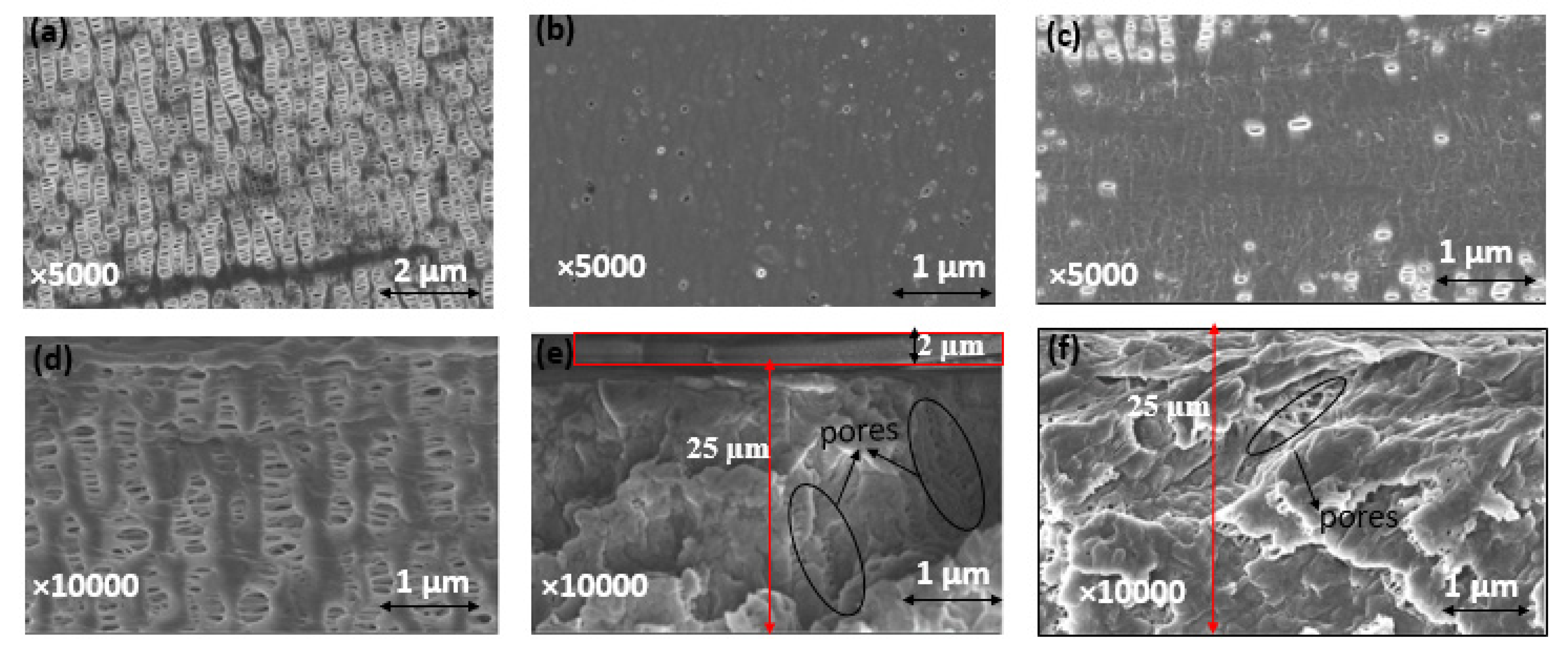
Chemical structures and purity of the polymer and monomer were determined by 1H NMR spectroscopy using CDCl3, deuterium or DMSO-d6 as solvents in the Bruker AscendTM 400 MHz Spectrometer. The polymer coating was confirmed by Bruker’s VERTEX 70v FT-IR Spectrometer in range of 4000–500 cm−1 with resolution of 2 cm−1. SEM analysis was done to study the homogeneity of the coating.
3.4.2. Electrolyte Uptake
Electrolyte uptake of membranes was determined by immersing the membranes in 6 M aqueous KOH for 24 h at room temperature. Membrane samples were taken out from the solution and their surface solution was removed to record their wet weight. The liquid electrolyte uptakes of the membranes were calculated from the difference of wet and dry weights of the membrane samples based on the following equation (Equation (1)):
where W
dry and W
wet are the weights of the membranes before and after absorbing the liquid electrolyte.
Volume swelling degree: dried membranes were immersed in 6 M KOH for 24 h at room temperature and the volume (area x thickness) of all the membranes was measured. The difference between the wet volume and dry volume was used to calculate the swelling ratio of the membranes according to the following Equation (2):
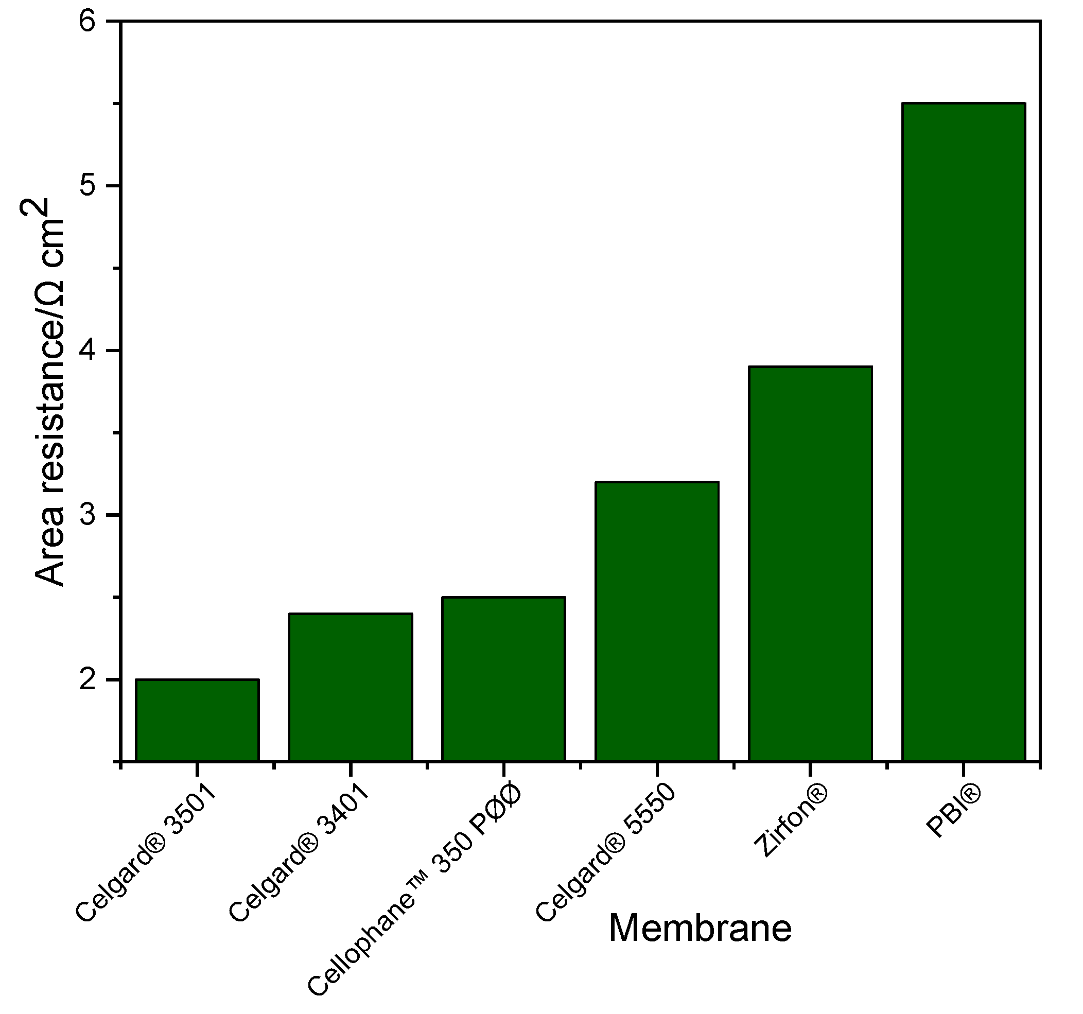
3.4.3. Ionic Conductivity
The ionic conductivity of the membranes was measured by electrochemical impedance spectroscopy (EIS) in the frequency range 13 MHz–5 Hz at room temperature. All membranes were immersed in 6 M KOH solutions for 24 h before measuring their conductivity. The membranes were taken out from the electrolyte solution, the surface KOH aqueous solution was removed and measured for their resistance. The membrane ionic conductivity (
) was calculated by the following formula (Equation (3)):
where l is the thickness of the membrane (cm), A is the active area of the membrane sandwiched between two electrodes (0.0314 cm
2) and R is the electric resistance of the membrane (Ω).
3.4.4. Rheometry
Rotational rheometry was performed using a stress-controlled rheometer Discovery HR-3 (TA instruments). PPO-DAPCl viscosity was determined with a cone-plane geometry (D = 60 mm, 1° angle), whereas FAA viscosity was determined using a bob-in-cup geometry (bob diameter = 28 mm, bob length = 42 mm and cup diameter = 30 mm), due to sample lower viscosity. Measurements were performed at 25 °C with the aid of a Peltier plate integrated system and an anti-evaporation tool was used to prevent changes in sample properties. Steady state measurements were obtained by applying a constant shear rate from 0.01 to 100 s−1 and when shear stress (or torque) signal was stabilized, the measurement was taken. Validation of measurement was performed by applying decreasing steps from 100 to 0.01 s−1 and no significant differences were found. Lower shear rates resulted in torque values that were outside the rheometer’s range of measurement, so these values were not included.
3.4.5. Membrane Density
The density (ρ) of the membranes was measured by density measurement kit (Mettler-Toledo), which contains weighting pans at ambient and immersed in a solvent at 20 °C using toluene as liquid phase. The prepared membranes in OH- form were dried at 60 °C under vacuum for 24 h.
The membranes density in g cm
−3 was calculated by the following Equation (4):
where m
ambient and m
toluene are weights of the membrane at ambient and in toluene, respectively.
ρtoluene is density of toluene (0.87 g mL−1).
3.4.6. Mercury Porosimetry
Mercury (Hg) intrusion measurements (Quantachrome PoreMaster) were used to determine the intruded volume, volume of pores/mass of membrane (cm3 g−1) of the pristine and modified membranes.
3.4.7. Alkaline Stability
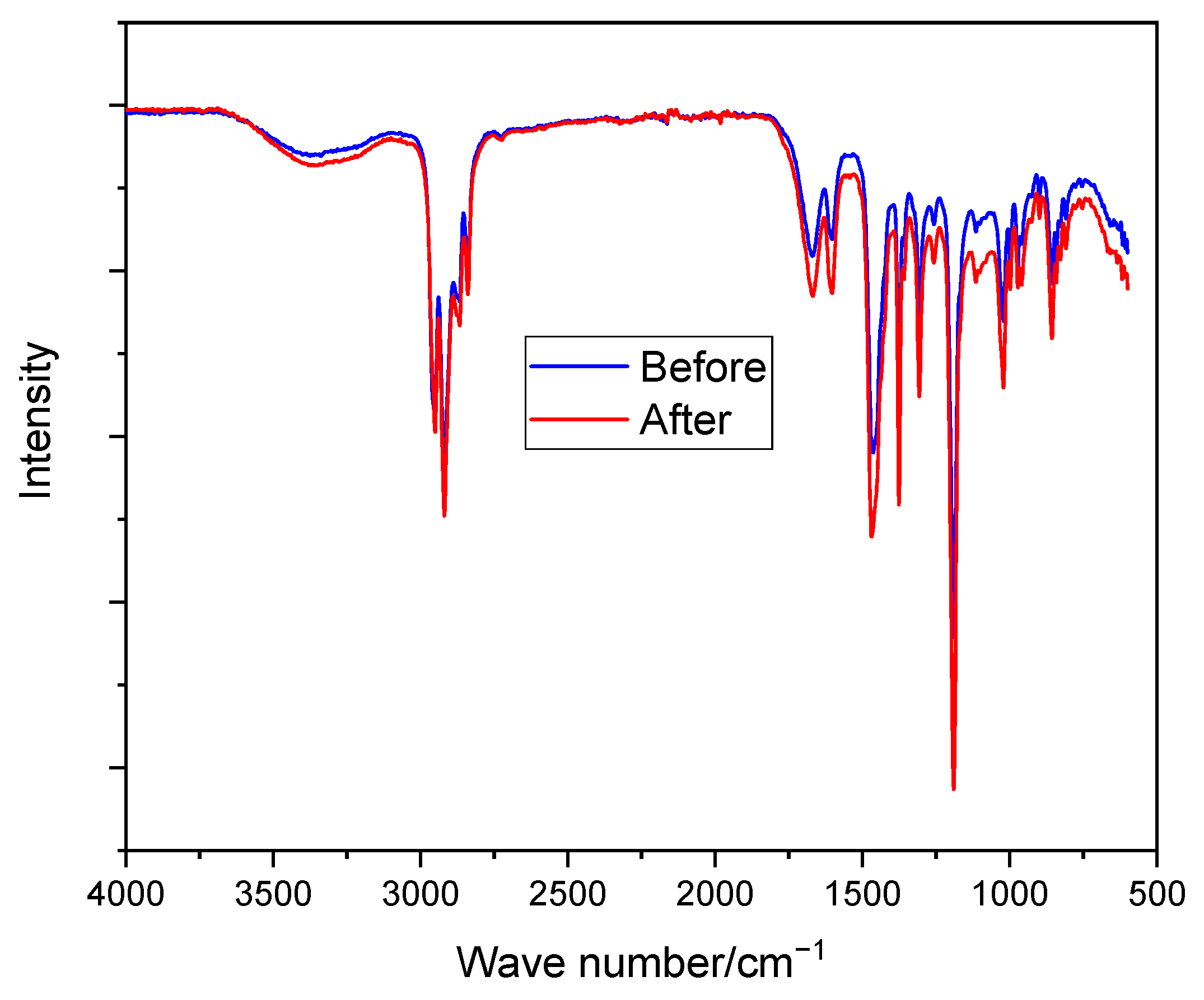
The alkaline stability of the modified membrane (PPO-3.45 + 3501) was studied by immersing the membranes in a typical solution used in Zn–air batteries i.e., 6 M KOH for 10 days at room temperature. The electrolyte was replaced every 48 h. The stability of the membranes was investigated by comparing the structure (by FTIR analysis) of the membranes before and after immersion in the alkaline solution.
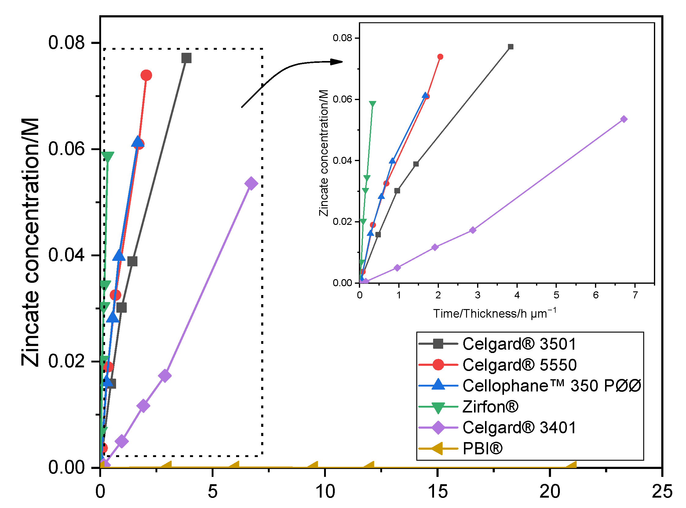
3.4.8. Zincate Ion Crossover
The crossover of Zn(OH)
42− ions through both the commercial and modified membranes was tested using a self-made diffusion cell (
Figure S6). The enriched side of the diffusion cell consists of 0.3 M of Zn(OH)
2 dissolved in 6 M aqueous KOH solution (15 mL). Whereas, the deficiency chamber was filled with only 6 M KOH aqueous solution (15 mL). The membrane sample was placed between the two compartments. At predefined period of times, a 0.1 mL sample was taken from the right-side chamber. The time-dependent concentration of Zn(OH)
42− ions in the right chamber was then determined using atomic absorption spectroscopy (AAS, PinAAcle
™ 900F, PerkinElmer (Waltham, MA, U.S)). A wavelength of 213.86 nm and 0.7 nm slit was used to determine the concentration of Zn in each sample solution. The diffusion coefficients (D) of Zn(OH)
42− ions of the different membranes were calculated from the following Equation (5) [
64]:
After integration, by assuming volume of the right chamber (
VB) does not change with time, Equation (5) can be changed to:
where D is the diffusion coefficient of Zn(OH)
42− ions through the membrane (m
2 min
−1), t is the time (min), A is the effective area of the membrane (~0.5 cm
2), L is the thickness of the membrane (m), C
A and C
B are the zincate concentrations (mol L
−1) in the enriched and deficiency chambers, respectively.
3.4.9. Single Cell Assembly and Electrochemical Performance
A single cell used for this study is identical to the best performing cell design reported in a previous study [
43], which has a serpentine flow field of CuNi plate (
Figure 8). A catalyst coated electrode (CCE) was used for the air cathode. The catalyst ink was prepared by mixing a Pt/C catalyst (40% Pt, Alfa Aesar, (Thermo Fisher, Kandel, Germany)) with Pt loading at 1 mg cm
−2, isopropanol and deionized water. The prepared ink was then sonicated in an ultrasonic water bath for 15 min and sprayed onto a geometric area of 25 cm
2 (5 × 5 cm and 0.0235 cm thickness) gas diffusion layer (SGL Carbon, 29BC, FuelCellStore, College Station, TX, USA). The CCE was placed between the membranes and the cathode bipolar plate. The Zn slurry (
Table 6) was prepared using the same method and chemicals as in a previous study [
65]. Each solution was mixed at 4000 rpm for 3 min.
The diameters of zinc particles were measured using a laser diffraction analyzer (Mastersizer 2000, Malvern Panalytical (Malvern, United Kingdom). The zinc used in this study can be classified as microparticles, with a mass-median-diameter D50 = 65.5 µm. Only 10% of the particles are smaller than 46.5 µm.
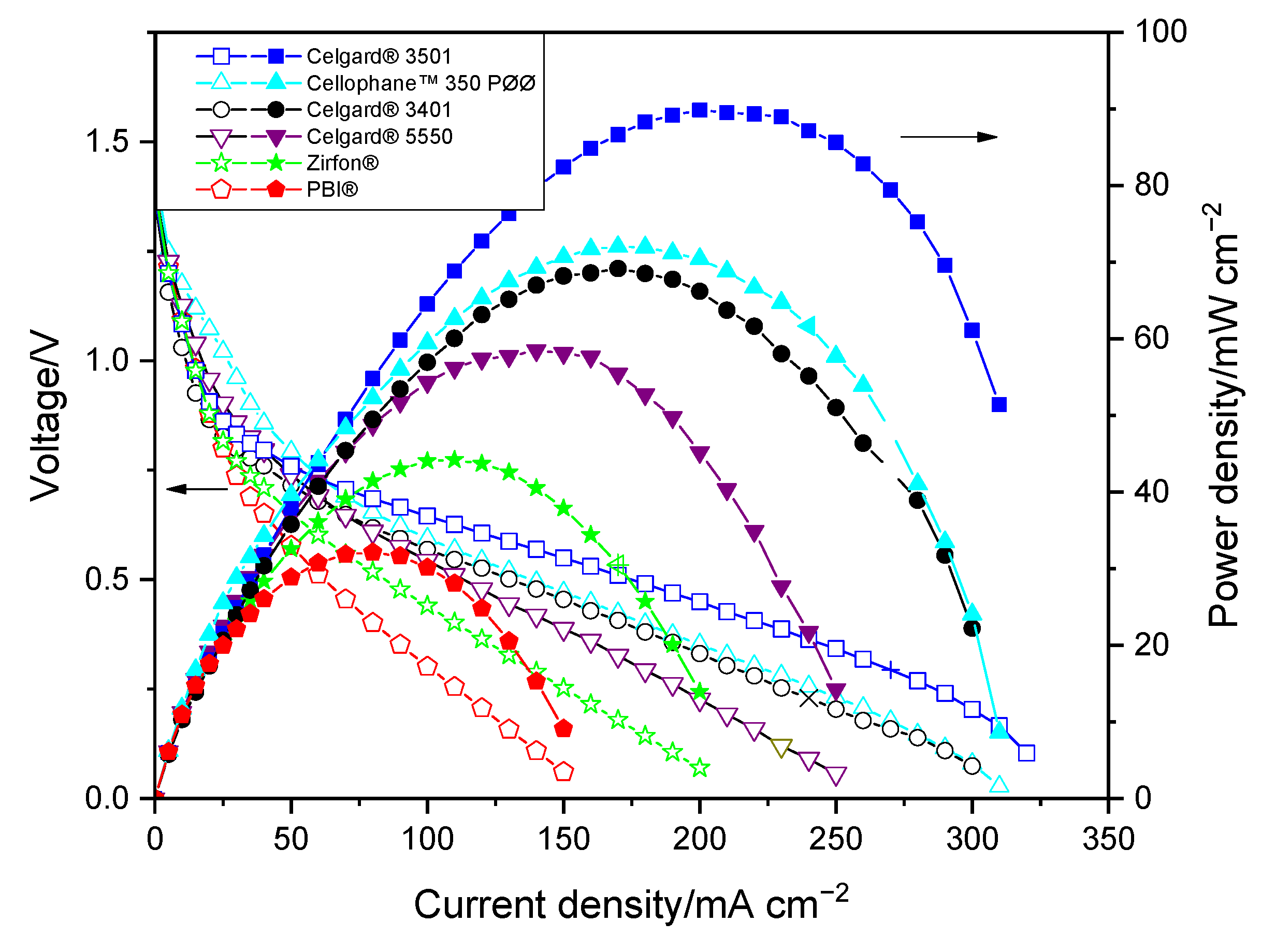
In order to determine electrochemical performances of each membrane, current–voltage characteristic curves (polarization curves) and EIS were measured. BaSyTec GSM Battery Test System (BaSyTec GmbH, Asselfingen, Germany) was used for current–voltage characterization while Zahner IM6 workstation was used for impedance spectra. The cell resistance of the battery employing the membranes was determined from the slope of the current density–voltage (IV) curves. In addition, the ohmic resistances of the cell were assessed by EIS measurements which were carried out at 1.3 V. All membranes were immersed in 1 M KOH solutions for 24 h before measuring their resistance. During the measurements, Zn slurry was flowing into anode compartment at 160 mL min
−1 flow rate while synthetic air was flowing into cathode at 100 mL min
−1 flow rate. At each current density, the voltage was recorded for 30 s and averaged due to the fluctuation of a slurry electrode flowing into the single cell.
Figure 8 presents the schematic representation of the Zn slurry–air flow battery used.
4. Conclusions
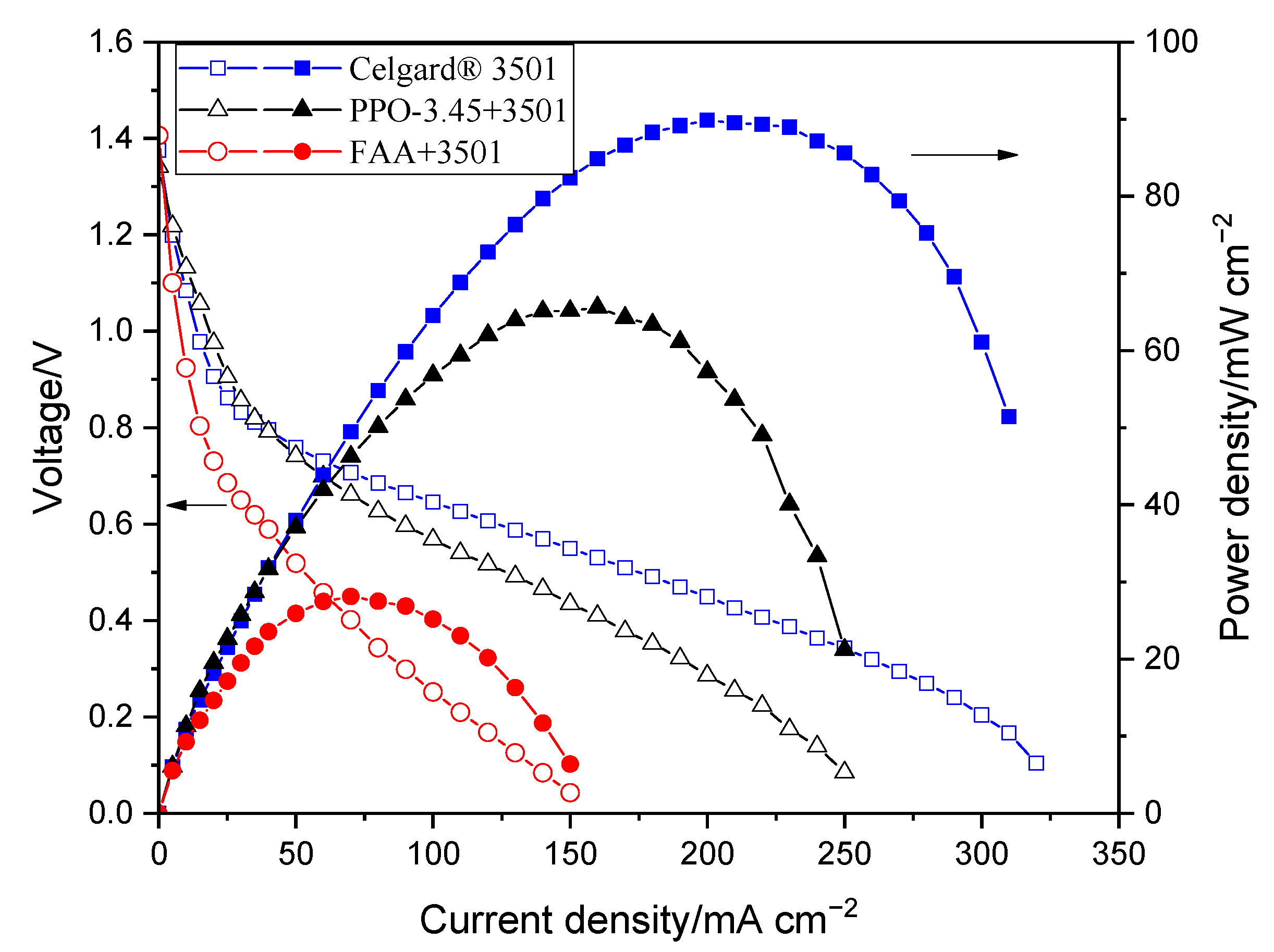
The order of peak power density of the cell employing the commercial membranes in decreasing order was Celgard
® 3501 > Cellophane™ 350 PØØ ≈ Celgard
® 3401> Celgard
® 5550 > Zirfon
® > PBI
®, in agreement with their respective cell resistances. However, the membranes with good polarization characteristics of Zn slurry–air battery, the Cellophane™ 350 PØØ and the three Celgard
® membranes showed a significant crossover of the soluble Zn(OH)
42− ions (diffusion coefficient being greater than 6.5 × 10
−12 m
2 s
−1). To reduce the crossover of Zn(OH)
42− ions through the porous membranes, Celgard
® 3501 was modified using two different ion-selective polymers (
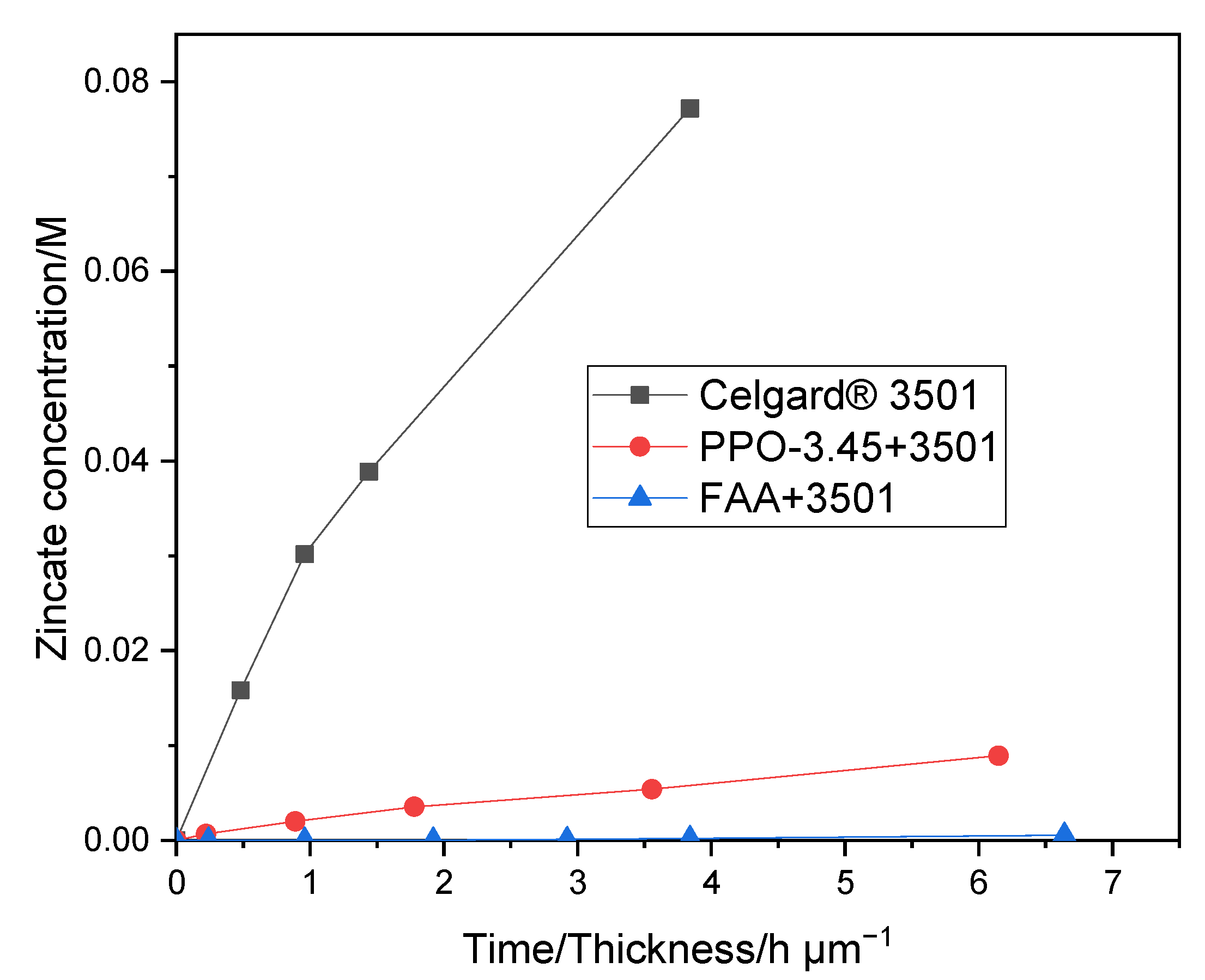
Supplementary Materials Table S1). In PPO-3.45 + 3501, the polymers were found to be coated and impregnated on the support membrane. Whereas, in the second work, the FAA polymer impregnated into the porous structure of the commercial membrane. Compared to the pristine Celgard
® 3501, the PPO 3.45+ 3501 membrane showed 18-fold lower crossover of Zn(OH)
42− ions (5.2 × 10
−13 vs. 9.2 × 10
−12 m
2 s
−1). The modified membrane-based battery delivered a high maximum power density 66 mW cm
−2, lower than that of Celgard
® 3501-based cell (90 mW cm
−2) due to the increase in resistance of the membrane associated with the partial filling of the pores with ionomers. In summary, modified membranes are promising candidates for use in rechargeable Zn slurry–air flow batteries, thus further optimizations are required.


 ,
, 

