Article

Research on Molecular Structure and Electronic Properties of Ln3+ (Ce3+, Tb3+, Pr3+)/Li+ and Eu2+ Co-Doped Sr2Si5N8 via DFT Calculation

1
State Key Laboratory of Advanced Technology for Materials Synthesis and Processing, Wuhan University of Technology, Wuhan 430070, China
2
School of Chemistry, Chemical Engineering and Life Sciences, Wuhan University of Technology, Wuhan 430070, China
*
Authors to whom correspondence should be addressed.
Molecules 2021, 26(7), 1849; https://doi.org/10.3390/molecules26071849
Submission received: 2 March 2021 / Revised: 18 March 2021 / Accepted: 21 March 2021 / Published: 25 March 2021

Abstract

:
We use density functional theory (DFT) to study the molecular structure and electronic band structure of Sr2Si5N8:Eu2+ doped with trivalent lanthanides (Ln3+ = Ce3+, Tb3+, Pr3+). Li+ was used as a charge compensator for the charge imbalance caused by the partial replacement of Sr2+ by Ln3+. The doping of Ln lanthanide atom causes the structure of Sr2Si5N8 lattice to shrink due to the smaller atomic radius of Ln3+ and Li+ compared to Sr2+. The doped structure’s formation energy indicates that the formation energy of Li+, which is used to compensate for the charge imbalance, is the lowest when the Sr2 site is doped. Thus, a suitable Li+ doping site for double-doped lanthanide ions can be provided. In Sr2Si5N8:Eu2+, the doped Ce3+ can occupy partly the site of Sr12+ ([SrN8]), while Eu2+ accounts for Sr12+ and Sr22+ ([SrN10]). When the Pr3+ ion is selected as the dopant in Sr2Si5N8:Eu2+, Pr3+ and Eu2+ would replace Sr22+ simultaneously. In this theoretical model, the replacement of Sr2+ by Tb3+ cannot exist reasonably. For the electronic structure, the energy level of Sr2Si5N8:Eu2+/Li+ doped with Ce3+ and Pr3+ appears at the bottom of the conduction band or in the forbidden band, which reduces the energy bandgap of Sr2Si5N8. We use DFT+U to adjust the lanthanide ion 4f energy level. The adjusted 4f-CBM of CeSr1LiSr1-Sr2Si5N8 is from 2.42 to 2.85 eV. The energy range of 4f-CBM in PrSr1LiSr1-Sr2Si5N8 is 2.75–2.99 eV and its peak is 2.90 eV; the addition of Ce3+ in EuSr1CeSr1LiSr1 made the 4f energy level of Eu2+ blue shift. The addition of Pr3+ in EuSr2PrSr2LiSr1 makes part of the Eu2+ 4f energy level blue shift. Eu2+ 4f energy level in EuSr2CeSr1LiSr1 is not in the forbidden band, so Eu2+ is not used as the emission center.

1. Introduction

Red fluorescent materials are essential parts of improving the color rendering index in phosphor-converted WLEDs (pc-WLEDs) and have high application value. With rare-earth ions as activating ions, as a representative of the matrix of red phosphors, Sr2Si5N8 alkaline earth metal silicon nitride has been extensively studied in recent years [1,2,3]. When Eu2+ is used as the activating ion, the luminous intensity is the highest. Simultaneously, Sr2Si5N8:Eu2+ has become the representative of commercial red fluorescent materials because of its outstanding fluorescence performance in all aspects [4]. However, the main problem is that Sr2Si5N8:Eu2+ is sensitive to temperature, and Sr2Si5N8:Eu2+ luminous intensity is significantly reduced when the temperature is higher. Considering that M2Si5N8 is a layered or similar layered structure, its openness is relatively high so that the above problems can be solved through component engineering [5].
The coordination environment, electronic structure, and morphological characteristics of the Eu2+ ion are several vital factors that affect phosphors’ luminescence performance. They determine the luminescence characteristics by indirectly changing the degree of crystal field splitting (CFS) [6], nephelauxetic effect (NE), the highest and lowest 5d energy level splitting [7,8]. For example, from both experiments and calculations Li [9] and Bulloni [10] proved that Ca2+ partially replaced Eu2+ in Sr2Si5N8 matrix’s emission peaks, which tended to appear red-shifted in Eu2+ occupied eight coordination sites, though its stability was reduced. Liu used Ba2+ to replace partial Sr2+ in Sr2Si5N8, after the substitution, the emission peak was blue-shifted. As Eu2+ in the ten-coordinate structure is more stable than the eight-coordinate structure, its thermal stability is improved. Chen [11] performed a doping modification based on Sr2Si5N8:Eu2+. In Sr2Si5N8:Eu2+, part of Al3+ is used to replace Si4+. As the Al-N bond length is longer than that of Si-N, the bond length between Eu2+ and surrounding N3− is shorter, the crystal field intensity increases, and the emission peak position is red-shifted. Wang [12] used partial AlO+ instead of SiN+, and the effects of the increase in the crystal field and the increase in electronegativity cancelled each other out, rendering the peak position unchanged, but the thermal stability and strength increased. In Rb3Ysi2O7:Eu2+ system, the weak covalent interaction of Eu2+ and O2− prevented Eu2+ from showing red emission [13]. The above-mentioned previous studies had found that different activating ions and ligand sites affected the energy level distribution of the activated ions and f orbitals, thereby affecting the luminescence performance.
Doping with more than one lanthanide ion can make up for the deficiency of one lanthanide ion doping. For example, Li [14] successfully introduced Gd3+/Er3+/Lu3+ into Bi2Mo6 to enhance its photocatalytic performance. Tang [15] introduced Ce3+ and Tb3+ into Na3SrMg11(PO4)9. There are relatively few reports on the lanthanide Eu2+ doped with M2Si5N8 as the base material and further doped with another lanthanide. The study found that Tb3+ and Eu2+ co-doped Sr2Si5N8 has a 20% increase in emission intensity [16]. Therefore, we want to systematically study the changes in the molecular structure and luminescence properties of Eu2+ and other Ln3+ co-doped systems. Among many lanthanides, the excitation spectrum of Pr3+4f-5d is relatively simple [8]. In the [Xe] (near nuclear pseudopotential electron) 4f15d1 configuration during the excitation, Pr3+ has only one 4f energy level, which can occupy two different electrons. Tb’s advantage is that in 4f75d, the 4f7[8S7/2] energy level is relatively stable, and the next higher 4f7[6PJ]5d1 energy level is about 3.5–4.0 eV higher. Therefore, it can be observed that 4f8–4f7(8S7/2)5di turns into an isolated state. Ce3+ is widely used as an activating ion in various fluorescent systems: Lu3Al5O12:Ce3+ [17], LaSi6N11:Ce3+ [18], Tb3Al5O12:Ce3+ [19], In summary, so we prefer to use any one of Ce3+, Pr3+, Tb3+ and Eu2+ doping for the Sr2Si5N8 matrix to explore the changes in molecular structure and properties.
Li [20] used Ce3+ and Li+ co-doping to replace two Sr2+, among which Li+ was used as a charge compensator for the charge imbalance caused by the partial replacement of Sr2+ by Ln3+. Li+ was widely used in phosphor doping such as CaLiAl3N4 [21], Sr4LiAl11N14 [22], Li2Ca2Mg2Si2N6 [23].
To realize the fundamental principal research on the luminescence characteristics, Fang [24] used the first principles to calculate the molecular structure and energy band structure of M2Si5N8 (M = Ca, Sr). Shen [25] studied the band structure of Sr2Si5N8:Eu2+ through first-principles calculations and combined experiments to reveal the mechanism of luminescence. Density functional theory (DFT) based on first-principles ideas has been successfully applied to the study of microscopic particle systems. In this paper, combined with previous studies, first-principles calculations are used to study the model of Ce3+, Pr3+, Tb3+, respectively, with Li+ co-doped Sr2Si5N8 matrix system and Ce3+/Pr3+/Tb3+, respectively, with Eu2+, Li+ three types of ions co-doped Sr2Si5N8 matrix. The optimized structural parameters of the co-doping model for different ion species and sites are presented. We calculate the energy band and density of states of varying doping systems to analyze the electronic structure.

2. Results and Discussion

2.1. Structures Distortion of Doped Models

In Table 1, a (Å), b (Å), c (Å) are the three sets of edge lengths of the unit cell. α, β, γ/(°) are, respectively, the angle between b and c; a and c; a and b. Polyhedral volume (Å3) is the coordination polyhedron volume of Ln and N. Distortion index (Å) is the distance a ligand moves after the d/f orbital energy level splits and stabilizes, which reflects distortion effect. Distortion effect: For transition element/rare earth element ions with a high coordination number (>6), high-spin d/f orbitals and low-spin d/f orbitals are unstable in regular polyhedrons, which will cause these d/f orbits to undergo further splitting in energy, in order to stabilize the ion, causing the coordination relationship to deviate from the symmetry of the regular polyhedron. Effective coordination number means that due to the regular coordination polyhedron’s structural distortion, the bond length between the ligand and the central atom changes, resulting in non-integer coordination.
The structure of TbSr2LiSr2-Sr2Si5N8 cannot converge after optimization. This model is unlikely to exist in the actual doping process, so subsequent calculations are not considered. The ionic radius of Sr2+ (1.18 Å), Eu2+ (1.17 Å), Ce3+ (1.02 Å), Pr3+ (0.99 Å), Tb3+ (0.92 Å), Li+ (0.68 Å) [26] (regardless of the coordination number) decreases from left to right; Eu2+, Ce3+/Li+, Pr3+/Li+ replace Sr2+ in turn. Due to the cationic ligand’s volume coarctation, the lattice constant and unit cell volume will be slightly smaller. The volume of the doped system is smaller than that of undoped lanthanide ions. Sr2Si5N8 volume, unit cell volume and doped ion radius are positively correlated. The average bond length between the lanthanide ion and N becomes shorter, making the bond between the lanthanide ion and the surrounding N stronger. The structure is more compact, the crystal field strength increases, and there will be a redshift tendency. Comparing the system in which the same lanthanide ion replaces eight-coordinate Sr2+ and ten-coordinate Sr2+, we find that the distortion degree of eight-coordinate Sr2+ is greater than that of ten-coordinate Sr2+. The formation of an eight-coordinate structure will produce a stronger electron cloud. The nephelauxetic effect (NE) produces a centroid shift, which has a synergistic effect with the above redshift. However, for trivalent lanthanide ions doped with the same coordination number, the different Li+ sites have almost no effect on the structure, which is only used to balance the charge.
Figure 1a shows the average bond length of [LnN8] and [LnN10], where AE represents the average bond length of [SrN8] and [SrN10] ligands in Sr2Si5N8 primitive unit cells. It can be seen from the figure that the average bond length decreases with the decrease in the ion radius. LnSr2LiSr1-Sr2Si5N8 has the most extended bond length on average, and LnSr1LiSr1-Sr2Si5N8 is the shortest. Figure 1b is a schematic diagram of CeSr1LiSr1-Sr2Si5N8 [CeN10] and EuSr1-Sr2Si5N8 [EuN10]. Atoms (10 N) are selected from the 32 N atoms to form a ten-coordinate polyhedron in the figure.

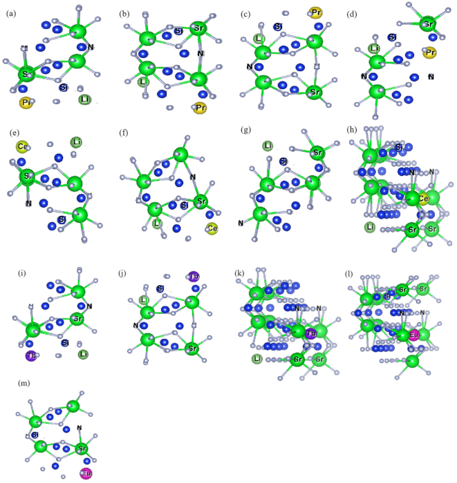
2.1.1. Ln-Li Distance and [SrN] Coordination Polyhedron Parameters of Sr2Si5N8:Ln3+/Li+

Figure 2 and Figure 3 describes the distance between Ln3+ and Li+. In the Sr2Si5N8 matrix, the selected doping (Sr) site is the same distance as Sr1-Sr1 and Sr2-Sr2, before being replaced by Ln3+/Li+, which has a distance of 5.748 Å; the distance is 3.467 Å between Sr1-Sr2. When Ln3+ and Li+ are doped to replace Sr1, in the order of Pr3+, Ce3+, Tb3+, the Ln-Li distances increased by 0.06 Å, 0.066 Å, 0.037 Å, respectively, and the degree of distortion was 1.05%, 1.14% and 0.64%. The overall deviation is not significant. When Ln3+/Li replaces different sites, the degree of distortion is always above 7.56%. From the perspective of the degree of lattice distortion, it is unlikely to occur in actual situations. When Ln3+/Li+ is doped to replace Sr2, the distortion degree of PrSr2LiSr2-Sr2Si5N8 and CeSr2LiSr2-Sr2Si5N8 is about 2.40%. After LnSr1LiSr-Sr2Si5N81 and LnSr2LiSr2-Sr2Si5N8 are doped to replace the Sr site, the distance between Ln-Li becomes longer, while LnSr1LiSr2 and LnSr2LiSr1 have shorter distances than that before doping.
Table 2 is the detailed description of Figure 4. In Table 2, we can see that when Ln doping replaces the site, [SrN10] tends to appear with two coordination types, one has an effective coordination number greater than 6.707 Å, and the other is less than 6.707 Å (6.707 Å is undoped [SrN10] effective coordination number). The effective coordination number of [SrN10] increases, while the effective coordination number of [SrN8] decreases. When Ln3+ doping replaces the Sr2 site, it is similar to Ln3+ substitution doping of the Sr1 site. [SrN8] tends to have two effective coordination numbers: the effective coordination number of [SrN8] increased, and the effective coordination number of [SrN10] decreased. The above phenomenon showed that after the structure optimization of Ln doping to replace Sr sites, the effective coordination number of [SrN] in other Sr sites is reduced with the same coordination number as doping to replace Sr is reduced. Combining with three factors: [LnN] coordination polyhedron structure, Ln-Li distance and [SrN] coordination polyhedron structure, the LnSr1LiSr1-Sr2Si5N8 doped-model can exist reasonably.

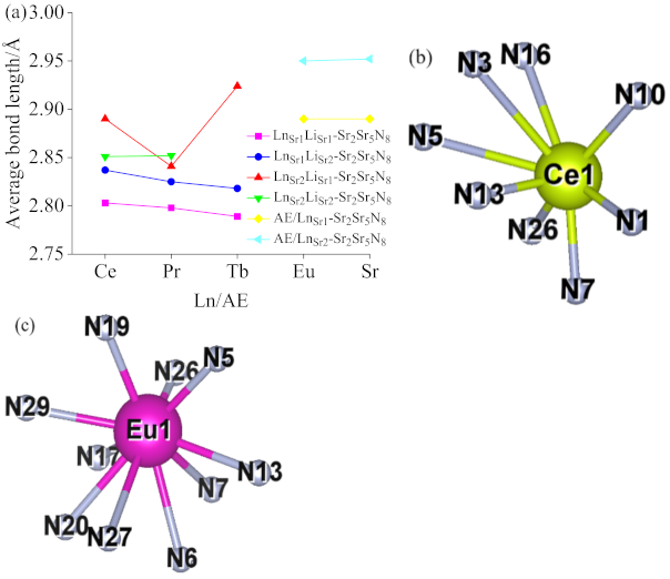
2.1.2. Lattice Constant and [LnN] Ligand Parameters of Sr2Si5N8:Ln3+/Li+/Eu2+

In Table 3, Ln3+/Eu2+ is the coordination polyhedron information of the ion and N. Except for the six ligand structures with three double lanthanide ions substituted for the Sr site, the other structures are not below the theoretical values. Only the following three doping models are Eu2+ and Ce3+ to replace Sr1, Eu2+ to replace Sr2, and Ce3+ to replace Sr1, Eu2+ replaces Sr2, Pr3+ replaces Sr2 in line with the actual structure. Neither Tb3+ nor Eu2+ co-doped systems are desirable. The unit cell volume and ligand structure of the co-doped system did not change significantly from the single-doped system.

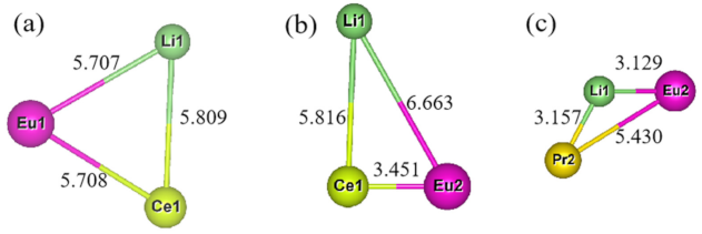
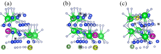
2.1.3. Ln-Li-Eu distance and [SrN] Coordination Polyhedron Parameters of Sr2Si5N8:Ln3+/Li+/Eu2+

After screening more than 30 models, a total of three models may exist stably after structure optimization. According to the order of Figure 4a–c, the distances before optimization of Ln-Li, Ln-Eu and Eu-Li are 5.748 Å, 5.748 Å, 5.748 Å; 5.748 Å, 3.467 Å, 6.713 Å; 3.467 Å, 5.748 Å, 3.467 Å. Among them, the distance between (a) and (b) does not change obviously before and after convergence, which is less than 0.1% compared with the original Sr-Sr distance. In summary, Combining Figure 5 and Table 4, we can draw the following conclusions: EuSr1CeSr1LiSr1 and EuSr2CeSr1LiSr1 can exist stably after Eu2+/Ce3+/Li+ co-doped with Sr2Si5N8, without considering the formation energy conditions. In the EuSr2PrSr2LiSr1-model, there are three distance types: Ln-Eu, Ln-Li, and Eu-Li. Compared with the original Sr sites, the distance changes are 5.6%, 8.9%, and 9.7%, respectively. In the Eu2+/Tb3+/Li+-Sr2Si5N8 model, the ionic radius of Tb3+ is too small, resulting in excessive structural distortion and difficulty in optimization convergence, so its structure cannot exist stably.

2.2. Formation Energy of Doped Models

Figure 6 is the formation energy diagram of Ce3+ (Tb3+, Pr3+)/Li+ co-doped Sr2Si5N8 with eight-coordinate (Sr1) and ten-coordinate (Sr2). From the definition of formation energy, the lower formation energy value means the target product is easier to form. Among all the values, Ce3+ and Li+’s formation energy co-doped in eight-coordinate and ten-coordinate systems, respectively, is the lowest. Pr3+ and Li+ co-doped together to replace eight-coordinate Sr has the highest formation energy. For Ce3+ and Tb3+, Ce3+ (Tb3+) and Li+ are, respectively, doped at the same Sr site to form lower energy. Pr and Li co-doped to replace ten-coordinate Sr2+ has the lower formation energy, and for co-doped to replace eight-coordinate Sr2+, the formation energy is the highest. Three kinds of lanthanide ions doping to replace Sr2 are easier to generate in theory. The formation energy of Li+ is lower when it is at the Sr2 site, so the fixed Li+ doping replaces Sr22+. Ce3+ (Tb3+, Pr3+)/Li+/Eu2+ co-doped Sr1 and Sr2 of Sr2Si5N8, in which Li+ is fixedly doped instead of Sr12+. EuSr1CeSr1LiSr1-Sr2Si5N8, EuSr2CeSr1LiSr1-Sr2Si5N8 and EuSr2PrSr2LiSr1-Sr2Si5N8′s formation energy levels are −1.2 eV, −5.2 eV, −5.18 eV. Compared with EuSr2PrSr2Li1-Sr2Si5N8, Sr2Si5N8:Pr3+/Li+ has a lower formation energy at around −2.8 eV. The formation energy of Sr2Si5N8:Ce3+/Li+/Eu2+ is 1.2 eV lower than Sr2Si5N8:Ce3+/Li+, so EuSr1CeSr1LiSr1-Sr2Si5N8, EuSr2CeSr1Li-Sr2Si5N8 could exist in theory.

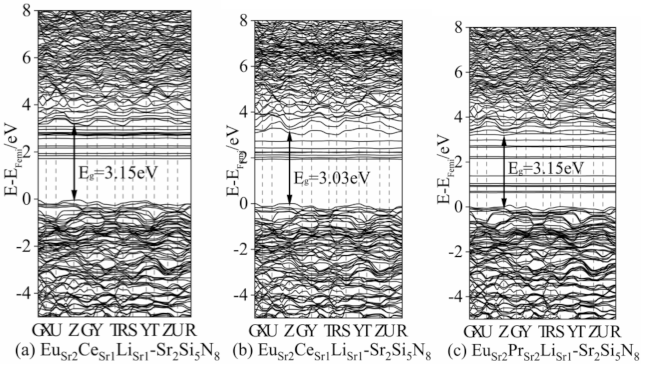
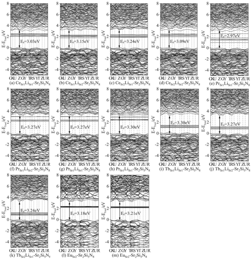
2.3. Band Structures and Density of States

We first calculated the ground state energy band and state density of Eu2+ single-doped Sr2Si5N8 and Tb3+ (Ce3+, Pr3+)/Li+ co-doped Sr2Si5N8 systems, as shown in Figure 7, for our subsequent calculations of Eu2+/Ce3+ (Tb3+, Pr3+)/Li+ ion co-doping, which provides a basis for comparison. The calculated bandgap of Sr2Si5N8:Eu22+ is 3.21 eV, which is slightly smaller than the experimental bandgap because the approximate processing of the DFT exchange-correlation term causes the bandgap to become narrower [27]. In the (a–l) ground-state band structure diagram, their direct bandgaps are CeSr1LiSr1-Sr2Si5N8: 3.03 eV, CeSr1LiSr2-Sr2Si5N8: 3.15 eV, CeSr2LiSr1-Sr2Si5N8:CeSr2LiSr1-Sr2Si5N8:Sr2Si5N8: 3.09 eV, PrSr1LiSr1-Sr2Si5N8: 2.97 eV, PrSr1LiSr2-Sr2Si5N8: 3.27 eV, PrSr2LiSr1-Sr2Si5N8: 3.27 eV, PrSr2LiSr2-Sr2Si5N8: 3.30 eV, TbSr1LiSr1-Sr2Si5N8: 3.30 eV, TbSr1LiSr2-Sr2Si5N8: 3.27 eV, TbSr1LiSr2-Sr2Si5N8: 3.24 eV. The high symmetry point G (reciprocal space), has the lowest energy at conduction band minimum (CBM), while some high symmetry points (Z) have the lowest CBM, and the highest valence band maximum (VBM). The lowest point of energy is between Z and G (Figure S1, Supporting Information). Due to the large energy gap between VBM and CBM (0.3 eV), the transition from VBM to CBM is an indirect bandgap transition. The direct bandgaps of (a–k) are 0.51 eV, 0.78 eV, 0.87 eV, 0.57 eV; 0.39 eV, 0.18 eV, 0.18 eV, 0.27 eV, 1.98 eV, 2.07 eV, 2.01 eV (Figure S1, Supporting Information); (a–k)’s indirect bandgaps are 3.03 eV, 3.15 eV, 3.24 eV, 3.09 eV, 2.97 eV, 3.27 eV, 3.27 eV, 3.30 eV, 3.30 eV, 3.27 eV, 3.24 eV. We compare four data from each of the same lanthanide elements. Excluding PrSr2LiSr2-Sr2Si5N8, the bandgap is 3.30 eV, and the other five LnnLin-Sr2Si5N8 are all about 3 eV. Except for PrSr2LiSr2-Sr2Si5N8, (f–h)’s 4f is closed to the CBM, the 4f energy levels of the ground-state lanthanide ions are distributed near the Fermi level (set VBM to 0), which is the premise of the lanthanide ion itself as the luminescence center. (a) CeSr1LiSr1-Sr2Si5N8 and (e) PrSr1LiSr1-Sr2Si5N8 have the smallest band gaps in their respective doping models, indicating that these two doping models have a high peak in the excited state and better luminous performance.
The states diagram’s density shows that the main components of VBM are 2p of N, 3s, 3p of Si, and CBM is mainly composed of 4f energy level of La, 5d, 5s orbitals of Sr and 3p, 3s of Si. Eu 6s, Eu 5p, Ce 6s, Ce 5p, Pr 6s, Pr 5p, Tb 6s and Tb 5p are minor in their contributions. The (Partial Density of State, PDOS) of Ce, Sr, N, Si in CeSr1LiSr1-Sr2Si5N8 are the same as the four PDOS in Sikander Azam’s calculation about Sr2Si5N8:Ce3+ [28]. Figure 7a has strong peaks at 2.04 eV and 2.46 eV, Figure S1b has approximately the same values at 2.07 eV, 2.10 eV, 2.25 eV, and 2.34 eV, while Figure S1c has a higher peak at 2.31 eV. Figure S1d has peaks of similar intensity at 2.25 eV, 2.43 eV, and 2.49 eV. The 4f energy level of Figure S1f–h is between 2.28 and 2.52 eV, and the 4f peak value of Pr3+ in Figure S1e is very high. If Pr3+ is the luminous center, the luminous intensity is much higher than Figure S1f–h. The 4f of Tb3+ in Figure S1j has a higher peak intensity at 1.17 eV, which has a good potential for activating ions.
Figure 7 shows the energy bands and state density of the three kinds of triple-doped ions systems, EuSr1CeSr1LiSr2-Sr2Si5N8, EuSr2CeSr1LiSr2-Sr2Si5N8, PrSr2EuSr2LiSr2-Sr2Si5N8. In EuSr1CeSr1LiSr2-Sr2Si5N8, Eu2+ is the main component in the forbidden band. Ce3+ is close to the bottom of the conduction band. EuSr2CeSr1LiSr2-Sr2Si5N8 is in the conduction band and has low intensity. Therefore, among the lanthanide ions of this system, only Ce3+ is the luminescence center. For PrSr2EuSr2LiSr2-Sr2Si5N8, the band distribution is relatively dense. The 5d electrons in the excited state may produce multi-level transitions [29].

Determination of DFT+U Parameters of Each System

In Table 5, as the value of Ueff increases from 0 to 8 eV, when Eu2+ is equal to 6 eV, the 4f electron orbital of Eu2+ appears at the top of the valence band. When Ueff = 8 eV, the filled state 4f orbital has wholly entered the valence band, and the energy level is about −1 eV (set the top of the valence band as the Fermi level, that is, Ef = 0 eV). When Ueff = 4 eV, Sr2Si5N8:EuSr12+ and Sr2Si5N8:EuSr22+’s 4f–CBM energy difference is 2.22 eV and 2.23 eV, respectively, according to the energy wavelength conversion formula:
E = h k C λ
In the above formula, E (energy)—eV, k (Planck’s constant) = 6.63 × 10⁻³⁴ J·s, k = 1.6 × 10⁻¹⁹ J/eV, C (speed of light) = 3 × 10¹⁷ nm/s, λ (wavelength)—nm. The parameters can be obtained in the following formula:
λ = 1240 E
The direct bandgaps of Figure 8a–c are 0.51 eV, 0.78 eV, 0.87 eV, 0.57 eV; 0.39 eV, 0.18 eV, 0.18 eV, 0.27 eV; 1.98 eV, 2.07 eV, 2.01 eV, respectively. The Ueff value makes 4f-CBM fall in the appropriate energy range, the Ueff introduced by (a–k) are: 5 eV, 5 eV, 5 eV, 6 eV; 4 eV, 6 eV, 6 eV, 6 eV; 2 eV, 2 eV, 2 eV, 2 eV. The energy difference of 4f-CBM in (a–k) with different Ueff is: 2.42 eV, 2.53 eV, 2.62 eV, 2.68 eV, 1.79 eV, 2.28 eV, 2.28 eV, 2.37 eV; 2.69 eV, 2.76 eV, 2.73 eV.
In summary, we add different Ueff to the strongest peak of the 4f energy level and the energy distribution range in Figure 8a–k to make it fall within the appropriate range. The energy ranges of 4f-CBM in Figure 8a–d are 2.42–2.85 eV, 2.80–3.03 eV, 2.65–3.13 eV, 2.67–2.91 eV, respectively. In Figure 8a, CeSr1LiSr1-Sr2Si5N8 is closer to the excitation energy range of Ce3+ doped Sr2Si5N8 from 2.85 to 3.25 eV [30] reported in the experiment, but Figure 8a has a global redshift of 0.43 eV. In Figure 7e–h, the energy ranges of 4f-CBM are 2.75–2.99 eV, 2.28–3.06 eV, 2.27–3.08 eV, 2.37–2.97 eV, respectively. In Figure 8e, PrSr1LiSr1-Sr2Si5N8 is closer to the excitation energy range of Pr3+ doped SrAl2O4 from 2.53 to 2.88 eV [30] reported in the experiment. The energy ranges of 4f-CBM in Figure 8i–k are 2.68–3.04 eV, 2.77–3.07 eV, 2.71–3.07 eV, respectively, which is far from the experimental excitation of Sr2Si5N8:Tb3+ [16]. The Ueff values of Eu2+ and Ce3+ are 4 eV and 6 eV, respectively, and the energy range is mainly 2.27–2.82 eV, and the peak value is 2.27 eV, 2.39 eV, 2.82 eV. In Figure S2b, the Eu2+ 4f energy level is not in the forbidden band. When Ce Ueff is 5 eV, the energy range of 4f-CBM is from 2.35 to 2.83 eV. The Eu2+, Pr3+ Ueff values in Figure S2c are, respectively, 1 eV, 7 eV, and Eu2+ 4f energy levels have three strong peaks of 2.19 eV, 2.25 eV, and 2.93 eV. Pr3+ has the highest peak intensity of 2.69 eV in 2.69–2.99 eV.

3. Material and Methods

3.1. Theoretical Models

Three lanthanide ions (Ln3+ = Ce3+, Pr3+, Tb3+) were selected as doping ions to dope Sr2Si5N8 and Sr2Si5N8:Eu2+, respectively. As shown in Figure 9a, there are two kinds of Sr doping sites, namely, eight-coordinate Sr1 [SrN8] (0.5000, 0.8734, 0.9997) and ten-coordinate Sr2 [SrN10] (0.7500, 0.1158, 0.8683). Since in the doped ions, Ln are all positively trivalent and Sr is bivalent to neutralize the entire system’s charge, every time a positive trivalent lanthanide ion is introduced to replace Sr2+, a Li+ is introduced to replace Sr2+ to keep the entire system electrically neutral. The chemical formula of Sr2Si5N8 doped with Ln3+/Li+ is LnSr1/Sr2LiSr1/Sr2Sr2Si5N8, while the chemical formula of Sr2Si5N8 doped with Ln3+/Li+/Eu2+ is LnSr1/Sr2EuSr1/Sr2LiSr1/Sr2-Sr2Si5N8. Figure 9b has established a 2 × 2 × 1 supercell (60 atoms) with a doping concentration of 12.5% for Ln3+, Eu2+, and Li+. If we continue to expand the unit cell to 3 × 2 × 1 to reduce the doping concentration, the calculation requires more K points than 5 × 8 × 6, and it is complicated for the structure to converge. Notably, 2 × 2 × 1 is the largest supercell structure that can be established under the premise that the structure can converge.

3.2. Computational Methods

When considering all ground-state calculations, density functional theory (DFT) calculations are performed in the Vienna AB Initio Simulation Package (VASP, Vienna ab initio simulation package) using the projector-augmented wave (PAW) method [31]. Exchange-correlation (XC, exchange-correlation) energy is described in the Perdew–Burke–Ernzerhof (PBE) method in generalized gradient approximation (GGA) [32]. The cutoff energy of all calculated plane wave bases is set to 500 eV. The energy convergence tolerance of the Sself-Cconsistent Ffield (SCF) is 10−4 eV. The convergence tolerance of the relaxation force is 0.01 eV/Å per atom. Sr2Si5N8:Eu2+ original unit cell model removed the energy band calculation.
To solve the problem that DFT cannot handle d and f electrons, the Hubbard model compensates for the strong correlation between d and f electrons by adding additional energy terms. The corrected energy’s form is as follows:
E D F T + U = E D F T + 1 2 I , σ n l U n l I n n l I σ 1 n n l I σ
There are many forms of Hubbard model correction. We choose the simplest Dudarev approximation [33]; the form is as follows:
U J 2 σ m 1 n m 1 , m 1 σ m 1 , m 2 n ^ m 1 , m 2 σ n ^ m 2 , m 1 σ
U and J are the critical parameters of Hubbard’s correction item, replaced by = (UJ). Different ions have different Ueff values in different host environments.
In the whole calculation process, a 5 × 8 × 6 k-point network is generated using the Monkhorst–Pack method with Γ as the center. In the calculation of the energy band structure, the high-symmetry K point and the appropriate reverse spatial path are determined according to the symmetry of the crystal lattice. The electronic configuration 3s23p2, 2s2p3, 4s24p65s2, 2s1, 5s25p66s24f7, 5s25p64f15d16s2, 5s26s25p65d14f2, and 4f85s26s25p65d1 correspond to Si, N, Sr, Li, Eu, Ce, Pr, and Tb in the pseudo-electron composition.
Regarding the calculation method of the effective coordination number, this article adopts Brunner’s method [34], which assumes that ionic or covalent bonds connect the central atoms of the surrounding atoms. In the established C.N principle, the energy standard is defined as each coordination. The bond energy between (Xi) and the central atom (M) is different from the bond energy between the nearest ligand (X0) and the central atom. The energy ratio E M X i :   E M X 0 is defined as the contribution of Xi atom to M atom C.N*. If the nearest atom is only affected by the Coulomb force, it is easy to get formula (5)
C . N i o n * = i E M X i / E M X 0 = i Υ M X 0 / Υ M X i
where Υ M X i is the bond length between the central atom and the ligand.
The formation of energy can evaluate the stability of the structure. The model after substitution and doping lattice can be described as the following formula (6):
Ef(Sr2Si5N8:Eu2+/Ln3+/Li+) = E(Sr2Si5N8:Eu2+/Ln3+/Li+)+3µ(Sr2+) − E(Sr2Si5N8) − µ(Eu2+) − µ(Ln3+) − µ(Li+)
In the above formula Ef(Sr2Si5N8:Eu2+/Ln3+/Li+) is the formation energy, E(Sr2Si5N8:Eu2+/Ln3+/Li+) is the energy calculated by SCF, µ(Sr2+), µ(Eu2+), µ(Li+) are the chemical potentials of Sr, Eu, Li, and Ln, respectively, and E(Sr2Si5N8) is the energy calculated by the lattice matrix SCF. For the chemical potential of the element, formula (7) can be used
µ(x) = E(Cell of X)/n
where µ(x) is the chemical potential of X, E (Cell of X) is the elemental unit cell of element X, and n is the number of X contained in the elemental unit cell.

4. Conclusions

In this study, two models of Sr2Si5N8:Ln3+/Li+ and Sr2Si5N8:Ln3+/Eu2+/Li+ were constructed. The calculation of Sr2Si5N8:Ln3+/Li+ and Sr2Si5N8:Eu2+ provides a basic reference for double-doped lanthanide ions. The introduction of Li+ and Ln3+ can achieve the design idea of neutralizing electrons and maintaining the original structure. Three dual-doped models of EuSr1CeSr1LiSr2-Sr2Si5N8, EuSr2CeSr1LiSr2-Sr2Si5N8, and EuSr2PrSr2LiSr2-Sr2Si5N8 were screened out. Among the three models mentioned, EuSr1CeSr1LiSr2-Sr2Si5N8 and EuSr2PrSr2LiSr2-Sr2Si5N8’s fluorescence performances are expected to exceed that of Sr2Si5N8:Eu2+, which can be regarded as a potential route to increase the quenching temperature of the phosphor. When Ce3+ Ueff in CeSr1LiSr1-Sr2Si5N8 is 5 eV, the energy range of 4f-CBM is 2.42 –2.85 eV. Compared with the experimentally reported excitation range of 2.85–3.25 eV, the redshift is 0.42 eV (75 nm). When Pr3+ Ueff in PrSr1LiSr1-Sr2Si5N8 is 4 eV, the energy range of 4f-CBM is 2.75–2.99 eV, and its peak value is 2.90 eV, which is similar to SrAl2O4:Pr3+ 430–490nm with peaks around 440 nm. In Sr2Si5N8:Ln3+/Li+/Eu2+, three convergent models of EuSr1CeSr1LiSr1-Sr2Si5N8, EuSr2CeSr1LiSr1-Sr2Si5N8, and EuSr2PrSr2LiSr1-Sr2Si5N8 were selected. The addition of Ce3+ in EuSr1CeSr1LiSr1-Sr2Si5N8 made the 4f energy level of Eu2+ blue shift. Similarly, the addition of Pr3+ in EuSr2PrSr2LiSr1-Sr2Si5N8 makes part of the Eu2+ 4f energy level blue shift. The Eu2+ 4f energy level in EuSr2CeSr1LiSr1-Sr2Si5N8 is not in the forbidden band, so Eu2+ is not used as the emission center.

Supplementary Materials

The following are available online. Figure S1: Densiy of states of doped structures: (a) CeSr1LiSr1-Sr2Si5N8; (b) CeSr1LiSr2-Sr2Si5N8; (c) CeSr2LiSr1-Sr2Si5N8; (d) CeSr2LiSr2-Sr2Si5N8; (e) PrSr1LiSr1-Sr2Si5N8; (f) PrSr1LiSr2-Sr2Si5N8; (g) PrSr2LiSr1-Sr2Si5N8; (h) PrSr2LiSr2-Sr2Si5N8; (i) TbSr1LiSr1-Sr2Si5N8; (j) TbSr1LiSr2-Sr2Si5N8; (k) TbSr1LiSr2-Sr2Si5N8; (l) EuSr1-Sr2Si5N8; (m) EuSr2-Sr2Si5N8. Figure S2: Densiy of states of doped structures: (a) EuSr1CeSr1LiSr2-Sr2Si5N8; (b) EuSr2CeSr1LiSr2-Sr2Si5N8; (c) PrSr2EuSr2LiSr2-Sr2Si5N8. Table S1: The Key information in the energy band structure of Sr2Si5N8:Ln3+/Li+, Eu2+. Table S2: The Key information in the energy band structure of Sr2Si5N8:Ln3+/Li+/Eu2+.

Author Contributions

Conceptualization, Z.Y., Q.S. and J.Z.; formal analysis, Z.Y.; software, Z.Y. and J.Z.; funding acquisition, M.L. and Q.S.; investigation, Z.Y. and J.Z.; methodology, Z.Y. and J.Z.; project administration, Z.Y. and M.L.; supervision, Z.Y., Q.S. and M.L.; writing—original draft, Z.Y.; writing—review and editing, Z.Y. and M.L. All authors have read and agreed to the published version of the manuscript.

Funding

The National Natural Science Foundation of China (Nos. 51872217 and 51521001), the “111” Project (No. B13035).

Institutional Review Board Statement

Not applicable.

Informed Consent Statement

Not applicable.

Data Availability Statement

The data that support the findings of this study are available from the corresponding authors upon reasonable request.

Conflicts of Interest

The authors declare that they have no known competing financial interests or personal relationships that could have appeared to influence the work reported in this paper.

Sample Availability

The samples of compounds are not available from authors.

References

  1. Li, Y.Q.; van Steen, J.E.J.; van Krevel, J.W.H.; Botty, G.; Delsing, A.C.A.; DiSalvo, F.J.; de With, G.; Hintzen, H.T. Luminescence properties of red-emitting M2Si5N8:Eu2+ (M = Ca, Sr, Ba) LED conversion phosphors. J. Alloys Compd. 2006, 417, 273–279. [Google Scholar] [CrossRef]
  2. Liu, Y.H.; Chen, L.; Zhou, X.F.; Liu, R.H.; Zhuang, W.D. Structure, luminescence and thermal quenching properties of Eu doped Sr2-xBaxSi5N8 red phosphors. J. Solid State Chem. 2016, 246, 145–149. [Google Scholar] [CrossRef]
  3. Chen, L.; Liu, R.-H.; Zhuang, W.-D.; Liu, Y.-H.; Hu, Y.-S.; Du, F. Effect of Eu2+ concentration on the thermal quenching mechanism of Sr2Si5N8:Eu2+ red phosphors. Chin. J. Lumin. 2015, 36, 371–376. [Google Scholar] [CrossRef]
  4. Seibald, M.; Rosenthal, T.; Oeckler, O.; Maak, C.; Tücks, A.; Schmidt, P.J.; Wiechert, D.; Schnick, W. New polymorph of the highly efficient LED-phosphor SrSi2O2N2: Eu2+-polytypism of a layered oxonitridosilicate. Chem. Mater. 2013, 25, 1852–1857. [Google Scholar] [CrossRef]
  5. Chen, L.; Liu, R.H.; Zhuang, W.D.; Liu, Y.H.; Hu, Y.S.; Zhou, X.F.; Ma, X.L. A study on photoluminescence and energy transfer of SrAlSi4N7: Eu2+, Ce3+ phosphors for application in white-light LED. J. Alloys Compd. 2015, 627, 218–221. [Google Scholar] [CrossRef]
  6. Daicho, H.; Shinomiya, Y.; Enomoto, K.; Nakano, A.; Sawa, H.; Matsuishi, S.; Hosono, H. A novel red-emitting K2Ca(PO4)F:Eu2+ phosphor with a large Stokes shift. Chem. Commun. 2018, 54, 884–887. [Google Scholar] [CrossRef] [PubMed]
  7. Shang, M.M.; Li, C.X.; Lin, J. ChemInform abstract: How to produce white light in a single-phase host? ChemInform 2014, 43, 1372–1386. [Google Scholar]
  8. Dorenbos, P. A review on how Lanthanide impurity levels change with chemistry and structure of inorganic compounds. ECS J. Solid State Sci. Technol. 2013, 2, R3001–R3011. [Google Scholar]
  9. Li, Y.Q.; de With, G.; Hintzen, H.T. The effect of replacement of Sr by Ca on the structural and luminescence properties of the red-emitting Sr2Si5B8:Eu2+LED conversion phosphor. J. Solid State Chem. 2008, 181, 515–524. [Google Scholar]
  10. Bulloni, C.; García-Fuente, A.; Urland, W.; Daul, C. Effect of Ca2+ codoping on the Eu2+ luminescence properties in the Sr2Si5N8:Eu2+ host lattice: A theoretical approach. Phys. Chem. Chem. Phys. 2015, 17, 24925–24930. [Google Scholar] [CrossRef]
  11. Chen, L.; Liu, R.H.; Zhuang, W.D.; Liu, Y.H.; Hu, Y.S.; Zhou, X.F.; Gao, W.; Ma, X.L. Structure, photoluminescence, and thermal quenching properties of Eu doped Sr2AlxSi5−xN8−x/3 red phosphors. CrystEngComm 2015, 17, 3687–3694. [Google Scholar] [CrossRef]
  12. Wang, T.; Zheng, P.; Liu, X.L.; Chen, H.F.; Bian, L.; Liu, Q.L. Effects of replacement of AlO+ for SiN+ on the structure and optical properties of Sr2Si5N8:Eu2+ phosphors. J. Lumin. 2014, 147, 173–178. [Google Scholar] [CrossRef]
  13. Qiao, J.; Ning, L.; Molokeev, M.S.; Chuang, Y.C.; Zhang, Q.; Poeppelmeier, K.R.; Xia, Z. Site-Selective Occupancy of Eu2+ Toward Blue-Light-Excited Red Emission in a Rb3YSi2O7:Eu Phosphor. Angew. Chem. Int. Ed. 2019, 131, 11645–11650. [Google Scholar]
  14. Li, H.; Li, W.; Liu, X.; Ren, C.; Miao, X.; Li, X. Engineering of Gd/Er/Lu-triple-doped Bi2MoO6 to synergistically boost the photocatalytic performance in three different aspects: Oxidizability, light absorption and charge separation. Appl. Surf. Sci. 2019, 463, 556–565. [Google Scholar] [CrossRef]
  15. Tang, W.; Ding, S.; Yuan, Y.; Xie, G. Effect of Ce3+ and Tb3+ codoping on luminescence properties of Na3SrMg11(PO4)9:Eu2+ phosphors. Opt. Mater. 2020, 106, 110003. [Google Scholar] [CrossRef]
  16. Peng, X.; Li, S.-X.; Liu, X.-J.; Huang, Y.-H.; Huang, Z.-R.; Li, H.-L. Syntheses and photoluminescence properties of Eu2+/Tb3+ doped Sr2Si5N8 phosphors. J. Inorg. Mater. 2015, 30, 397–400. [Google Scholar]
  17. Li, H.L.; Liu, X.J.; Huang, L.P. Luminescent properties of Luag: Ce phosphors with different ce contents prepared by a sol-gel combustion method. Opt. Mater. 2007, 29, 1138–1142. [Google Scholar] [CrossRef]
  18. Zorenko, Y.; Gorbenko, V.; Voznyak, T.; Zorenko, T.; Kuklinski, B.; Turos-Matysyak, R.; Grinberg, M. Luminescence properties of phosphors based on Tb3Al5O12 (TbAG) terbium-aluminum garnet. Opt. Spectrosc. 2009, 106, 365–374. [Google Scholar] [CrossRef]
  19. Zhong, J.Y.; Zhao, W.R.; Du, F.; Wen, J.; Zhuang, W.D.; Liu, R.H.; Duan, C.-K.; Wang, L.G.; Lin, K. Identifying the emission centers and probing the mechanism for highly efficient and thermally stable luminescence in the La3Si6N11: Ce3+Phosphor. J. Phys. Chem. C 2018, 122, 7849–7858. [Google Scholar] [CrossRef]
  20. Li, Y.Q.; de With, D.; Hintzen, H.T. Luminescence properties of Ce3+-activated alkaline earth silicon nitride M2Si5N8(M=Ca, Sr, Ba) materials. J. Lumin. 2006, 116, 107–116. [Google Scholar]
  21. Pust, P.; Wochnik, A.S.; Baumann, E.; Schmidt, P.J.; Wiechert, D.; Scheu, C.; Schnick, W. Ca[LiAl3N4]: Eu2+—A narrow-band red-emitting nitridolithoaluminate. Chem. Mater. 2014, 26, 3544–3549. [Google Scholar]
  22. Wilhelm, D.; Baumann, D.; Seibald, M.; Wurst, K.; Heymann, G.; Huppertz, H. Narrow-band red emission in the nitridolithoaluminate Sr4[LiAl11N14]: Eu2+. Chem. Mater. 2017, 29, 1204–1209. [Google Scholar] [CrossRef]
  23. Strobel, P.; Weiler, V.; Hecht, C.; Schmidt, P.J.; Schnick, W. Luminescence of the narrow-band red emitting nitridomagnesosilicate Li2(Ca1-xSrx)2[Mg2Si2N6]: Eu2+(x = 0 − 0.06). Chem. Mater. 2017, 29, 1377–1383. [Google Scholar] [CrossRef]
  24. Fang, C.M.; Hintzen, H.T.; de With, G.; de Groot, R.A. Electronic structure of the alkaline-earth silicon nitrides M2Si5N8(M=Ca and Sr) obtained from first-principles calculations and optical reflectance spectra. J. Phys. Condens. Matter 2001, 13, 67–76. [Google Scholar]
  25. Shen, T.-Y.; Wu, Y.; Shen, Y.-F.; Zou, Z.-G.; Zhang, F.; Long, Z.-J. Photophysical properties and electronic structure of Sr2Si5N8:Eu2+. J. Synth. Cryst. 2014, 43, 1212–1216. [Google Scholar]
  26. Xi, Q. Research on Ionic Radius. J. Hainan Norm. Univ. 2001, 14, 68–75. [Google Scholar]
  27. Zhang, L.G.; Jin, H.; Yang, W.Y.; Xie, Z.P.; Miao, H.Z.; An, L. Optical properties of single-crystalline alpha-Si3N4 nanobelts. Appl. Phys. Lett. 2005, 86, 061908. [Google Scholar] [CrossRef]
  28. Sikander, A.; Muhammad, I.; Ayaz, K.S.; Ali, Z.; Kityk, I.V.; Muhammad, S.; Al-Sehemi, A.G. Doping induced effect on optical and band structure properties of Sr2Si5N8based phosphors: DFT approach. J. Alloy. Compound. 2019, 771, 1072–1079. [Google Scholar] [CrossRef]
  29. Ten Kate, O.M.; Zhang, Z.; Dorenbos, P.; Hintzen, H.T.; Van der Kolk, E. 4f and 5d energy levels of the divalent and trivalent lanthanide ions in M2Si5N8 (M=Ca, Sr, Ba). J. Solid State Chem. 2013, 197, 209–217. [Google Scholar] [CrossRef]
  30. Chawla, S.; Kumar, N.; Chander, H. Broad yellow orange emission from SrAl2O4:Pr3+phosphor with blue excitation for application to white LEDs. J. Lumin. 2009, 129, 114–118. [Google Scholar] [CrossRef]
  31. Kresse, G.; Furthmüller, J. Efficiency of ab-initio total energy calcutions for metals and semiconductors using a plane-wave basis set. Comput. Mater. Sci. 1996, 6, 15–50. [Google Scholar] [CrossRef]
  32. Dufek, P.; Blaha, P.; Sliwko, V.; Schwarz, K. Generalized-gradient-approximation description of band splittings in transition-metal oxides and fluorides. Phys. Rev. B Condens. Matter 1994, 49, 10170–10175. [Google Scholar] [CrossRef] [PubMed]
  33. Dudarev, S.L.; Botton, G.A.; Savrasov, S.Y.; Humphreys, C.J.; Sutton, A.P. Electron-energy-loss spectra and the structural stability of nickel oxide: An LSDA+U study. Phys. Rev. B 1998, 57, 1505–1509. [Google Scholar] [CrossRef]
  34. Guo, H.; Wu, Q. The calculation method of effective coordination number. J. Shenyang Univ. Chem. Technol. 1991, 4, 245. [Google Scholar]
Figure 1. (a) Average bond length of [LnN8] and [LnN10]. (b) Structure diagram of [CeN8]. (c) Structure diagram of [EuN10].
Molecules 26 01849 g001
Figure 2. The distance change after Ln3+ and Li+ replace Sr1 and Sr2 in doped Sr2Si5N8 (ak) PrSr1LiSr1-Sr2Si5N8, PrSr1LiSr2-Sr2Si5N8, PrSr2LiSr1-Sr2Si5N8, PrSr2LiSr2-Sr2Si5N8, CeSr1LiSr1-Sr2Si5N8, CeSr1LiSr2-Sr2Si5N8, CeSr2LiSr1-Sr2Si5N8, CeSr2LiSr2-Sr2Si5N8, TbSr1LiSr1-Sr2Si5N8, TbSr1LiSr2-Sr2Si5N8, TbSr2LiSr1-Sr2Si5N8; (nl) is the Sr-Sr distance before doping.
Molecules 26 01849 g002
Figure 3. (ac): Ln-Li, Eu-Li, Eu-Ln’s distance diagram after EuSr1CeSr1LiSr1-Sr2Si5N8, EuSr2CeSr1LiSr1-Sr2Si5N8, EuSr2PrSr2LiSr1-Sr2Si5N8 doped with Sr2Si5N8 matrix.
Molecules 26 01849 g003
Figure 4. [SrN] coordination polyhedron diagram after substitution of Ln3+/Li+ for Sr1 and Sr2 sites in Sr2Si5N8 (am) Pr Sr1LiSr1-Sr2Si5N8, PrSr1LiSr2-Sr2Si5N8, PrSr2LiSr1-Sr2Si5N8, PrSr2LiSr2-Sr2Si5N8, CeSr1LiSr1-Sr2Si5N8, CeSr1LiSr2-Sr2Si5N8, CeSr2LiSr1-Sr2Si5N8, CeSr2LiSr2, TbSr1LiSr1-Sr2Si5N8, TbSr1LiSr2-Sr2Si5N8, TbSr2LiSr1-Sr2Si5N8, EuSr1-Sr2Si5N8, EuSr2-Sr2Si5N8.
Molecules 26 01849 g004
Figure 5. (ac): [SrN] Coordination Polyhedron Diagram after EuSr1CeSr1LiSr1-Sr2Si5N8, EuSr2CeSr1LiSr1-Sr2Si5N8, EuSr2PrSr2LiSr1-Sr2Si5N8 doped with Sr2Si5N8 matrix.
Molecules 26 01849 g005
Figure 6. Formation energies of Ln3+/Li+ elements co-doped Sr2Si5N8.
Molecules 26 01849 g006
Figure 7. Band structures of doped structures: (a) EuSr1CeSr1LiSr1-Sr2Si5N8; (b) EuSr2CeSr1LiSr1-Sr2Si5N8; (c) PrSr2EuSr2LiSr1-Sr2Si5N8.
Molecules 26 01849 g007
Figure 8. Band structures of doped structures: (a) CeSr1LiSr1-Sr2Si5N8; (b) CeSr1LiSr2-Sr2Si5N8; (c) CeSr2LiSr1-Sr2Si5N8; (d) CeSr2LiSr2-Sr2Si5N8; (e) PrSr1LiSr1-Sr2Si5N8; (f) PrSr1LiSr2-Sr2Si5N8; (g) PrSr2LiSr1-Sr2Si5N8; (h) PrSr2LiSr2-Sr2Si5N8; (i) TbSr1LiSr1-Sr2Si5N8; (j) TbSr1LiSr2-Sr2Si5N8; (k) TbSr2LiSr1-Sr2Si5N8; (l) EuSr1-Sr2Si5N8; (m) EuSr2-Sr2Si5N8.
Molecules 26 01849 g008
Figure 9. (a) Molecular structure of Sr2Si5N8; (b) 2 × 2 × 1 supercell of Sr2Si5N8: The selected atoms are Sr2.
Molecules 26 01849 g009
Table 1. Cell parameters and [LnN] polyheral structures of Sr2Si5N8 and Sr2Si5N8 doped by Ln (Ce3+, Pr3+, Tb3+)/Li+, Eu2+.
2 × 2 × 1Cell ParametersVolume (Å3)[LnN]
Polyhedral
Volume (Å3)
[LnN]
Distortion Index (Å)
[LnN]
Effective
Coordination Number
Supercellsa (Å)b (Å)c (Å)α,β,γ/(°)
Sr2Si5N8(Sr2)11.4986.8819.405α = β = γ = 90.0744.07448.8660.0626.707
Sr2Si5N8(Sr1)11.4986.8819.405α = β = γ = 90.0744.07432.6570.0755.448
EuSi2-Sr2Si5N811.4986.8769.403α = 89.9,
β = γ = 90.0
743.13148.5450.0725.771
EuSr1-Sr2Si5N811.4936.8769.402α = 90.1,
β = γ = 90.0
743.04632.3790.0904.728
CeSr1LiSr1-Sr2Si5N811.4926.8749.373α = 90.4,
β = γ = 90.0
740.45027.9210.1194.919
CeSr1LiSr2-Sr2Si5N811.5056.8699.376α = 90.1,
β = γ = 90
741.01027.8570.1104.776
CeSr2LiSr1-Sr2Si5N811.4856.8769.370α = 89.9,
β = γ = 90
739.91045.1910.0925.550
CeSr2LiSr2-Sr2Si5N811.5046.8639.380α = 89.7,
β = γ = 90
740.70044.3540.0905.597
PrSr1LiSr1-Sr2Si5N811.4876.8739.372α = 90.4,
β = γ = 90
739.83027.7970.1234.849
PrSr1LiSr2-Sr2Si5N811.5016.8729.372α = 90.1,
β = γ = 90.0
740.68027.6890.1144.645
PrSr2LiSr1-Sr2Si5N811.4986.8819.405α = β = γ = 90.0739.34045.2130.1015.420
PrSr2LiSr2-Sr2Si5N811.5026.8639.380α = 89.7,
β = γ = 90.0
740.45044.3450.0935.337
TbSr1LiSr1-Sr2Si5N811.4706.8639.360α = 90.5,
β = γ = 90.0
736.97027.3210.1544.676
TbSr1LiSr2-Sr2Si5N811.4936.8599.370α = 90.1,
β = γ = 90.0
738.97027.3000.1474.496
TbSr2LiSr1-Sr2Si5N811.4796.8509.376α = 89.9,
β = γ = 90.0
737.23044.9020.1504.724
Table 2. [SrN] Coordination polyhedron parameters of Sr2Si5N8 doped by Ln (Ce3+, Pr3+, Tb3+)/Li+.
2 × 2 × 1
Supercell
[SrN] Average Bond Length
(Å)
[SrN] Polyhedral Volume
3)
[SrN] Distortion Index
(Å)
[SrN] Effective
Coordination Number
[SrN]
Coordination Number
CeSr1LiSr1-Sr2Si5N82.99449.7000.07237.00010
2.94248.3170.07206.62010
2.88632.4050.07575.4208
CeSr1LiSr2-Sr2Si5N82.92547.6550.0637.07010
2.95448.8450.0736.35810
2.90735.1440.0865.0528
CeSr2LiSr1-Sr2Si5N82.95649.4400.0666.21110
2.96345.3590.0885.88910
2.87932.3490.0815.7418
CeSr2LiSr2-Sr2Si5N82.97549.2910.0755.98910
2.87034.0930.0805.3508
2.90933.7110.0675.8998
PrSr1LiSr1-Sr2Si5N82.94048.2890.0726.64610
2.99449.7340.0737.02210
2.88432.3350.0765.4348
PrSr1LiSr2-Sr2Si5N82.92347.6010.0627.14810
2.95648.9500.0726.37810
2.90735.1440.0855.0858
PrSr1LiSr2-Sr2Si5N82.92347.6010.0627.14810
2.90735.1440.0855.0858
2.95548.9500.0726.37810
PrSr2LiSr2-Sr2Si5N82.97049.1920.0736.08710
2.87234.1600.0815.3218
2.90833.6950.0685.8868
TbSr1LiSr1-Sr2Si5N82.93748.2330.0716.87410
2.99949.8210.0756.96810
2.87732.0960.0755.4678
TbSr1LiSr2-Sr2Si5N82.92347.6020.0617.23110
2.96349.3040.0736.11610
2.89934.9050.0835.1598
TbSr2LiSr1-Sr2Si5N82.88332.7330.0865.7298
2.95849.9140.0795.94010
2.95545.1910.0856.11210
EuSr1-Sr2Si5N82.94748.6900.0616.73510
2.95248.9140.0606.96210
2.88832.6580.0745.4498
EuSr2-Sr2Si5N82.95148.9040.0616.70110
2.88832.7060.0725.6258
2.88932.6410.0745.4538
2.94238.6570.0855.5368
Table 3. Cell parameters and [LnN] polyheral structures of Sr2Si5N8 co-doped Eu2+/Ce3+/Li+ and Eu2+/Pr3+/Li+.
2 × 2 × 1Cell ParametersVolume
3)
[LnN]
Polyhedral Volume
3)
[LnN]
Distortion Index
(Å)
[LnN]
Effective Coordination Number
Supercellsa
(Å)
b
(Å)
c
(Å)
α,β,γ
(°)
EuSr1CeSr1LiSr2-Sr2Si5N8(Eu)11.4906.8749.375α = 90.3, β = γ = 90.0740.47032.0420.09474.654
EuSr1CeSr1LiSr2-Sr2Si5N8(Ce)11.4906.8749.375α = 90.3, β = γ = 90.0740.47028.1120.12194.926
EuSr2CeSr1LiSr2-Sr2Si5N8(Eu)11.4926.8679.370α = 90.3, β = γ = 90.0739.47048.0940.06136.455
EuSr2CeSr1LiSr2-Sr2Si5N8(Ce)11.4926.8679.370α = 90.3, β = γ = 90.0739.47028.0460.12545.026
EuSr2PrSr2LiSr2-Sr2Si5N8(Eu)11.4806.86079.377α = 90.3, β = γ = 90.0738.56648.5740.09435.849
EuSr2PrSr2LiSr2-Sr2Si5N8(Pr)11.4806.86079.377α = 90.3, β = γ = 90.0738.56645.8760.08804.752
Table 4. [SrN] Coordination polyhedron parameters of Sr2Si5N8 doped by Ln (Ce3+, Pr3+, Tb3+)/Li+/Eu2+.
2 × 2 × 1
Supercell
[SrN] Average Bond Length
(Å)
[SrN] Polyhedral Volume
3)
[SrN]
Distortion Index
(Å)
[SrN]
Effective
Coordination Number
[SrN]
Coordination Number
EuSr1CeSr1LiSr12.94148.3610.06666.88410
2.98949.5460.07217.04010
2.88732.5070.07555.4068
EuSr2CeSr11LiSr12.94548.4440.07186.59010
2.99149.6910.07057.03910
2.88032.2410.07555.4278
EuSr2PrSr21LiSr12.96049.2480.06466.26010
2.86331.8950.08255.6808
2.88932.6230.07535.3608
Table 5. Energy level difference of Eu 4f-CBM of Sr2Si5N8:Eu2+ with different Ueff parameters.
Ueff (eV)Eu2+ 4f—CBM(eV)
Eu12+Eu22+
00.840.84
21.481.50
42.222.23
62.862.93
Publisher’s Note: MDPI stays neutral with regard to jurisdictional claims in published maps and institutional affiliations.

