Article

Advances in Mixer Design and Detection Methods for Kinetics Studies of Macromolecular Folding and Binding on the Microsecond Time Scale

Molecular Therapeutics Program, Fox Chase Cancer Center, Philadelphia, PA 19111, USA
*
Author to whom correspondence should be addressed.
Molecules 2022, 27(11), 3392; https://doi.org/10.3390/molecules27113392
Submission received: 29 April 2022 / Revised: 20 May 2022 / Accepted: 21 May 2022 / Published: 25 May 2022

Abstract

:
Many important biological processes such as protein folding and ligand binding are too fast to be fully resolved using conventional stopped-flow techniques. Although advances in mixer design and detection methods have provided access to the microsecond time regime, there is room for improvement in terms of temporal resolution and sensitivity. To address this need, we developed a continuous-flow mixing instrument with a dead time of 12 to 27 µs (depending on solution viscosity) and enhanced sensitivity, sufficient for monitoring tryptophan or tyrosine fluorescence changes at fluorophore concentrations as low as 1 µM. Relying on commercially available laser microfabrication services, we obtained an integrated mixer/flow-cell assembly on a quartz chip, based on a cross-channel configuration with channel dimensions and geometry designed to minimize backpressure. By gradually increasing the width of the observation channel downstream from the mixing region, we are able to monitor a reaction progress time window ranging from ~10 µs out to ~3 ms. By combining a solid-state UV laser with a Galvano-mirror scanning strategy, we achieved highly efficient and uniform fluorescence excitation along the flow channel. Examples of applications, including refolding of acid-denatured cytochrome c triggered by a pH jump and binding of a peptide ligand to a PDZ domain, demonstrate the capability of the technique to resolve fluorescence changes down to the 10 µs time regime on modest amounts of reagents.

Graphical Abstract

1. Introduction

Fast time-resolved measurements are essential for gaining mechanistic insight into biological processes such as enzyme catalysis, protein and RNA folding and protein–ligand interactions, which often occur on a time scale extending into the microsecond range. Various techniques have been used to trigger reactions, including temperature and pressure jumps [1,2,3], flash photolysis [4], electron transfer [5], hydrodynamic focusing under laminar flow conditions [6,7] and turbulent mixing [8,9,10,11]. Flash photolysis and temperature jump techniques have been used to trigger protein folding reactions within a few microseconds or less, but they have been limited in scope because of the requirement of a photochemical trigger and cold-denatured initial state, respectively. Elegant hydrodynamic focusing experiments have been developed that can achieve about 90% efficiency for mixing a macromolecule and a small molecule (e.g., denaturant or acid) in less than 10 µs [7,12], but they have not been applied widely due to the high protein concentrations and challenging laser optics needed for monitoring reaction progress in a thin (<1 µm) layer of protein solution. In contrast, rapid mixing of two (or more) reactants by turbulent mixing has proven to be a more generally applicable and versatile approach for initiating biomolecular reactions [11,13,14,15].
The time resolution of a rapid mixing instrument is limited by the instrumental dead time, i.e., the time delay between the onset of mixing and the first reliable instrumental reading of reaction progress, which in practice is determined empirically by extrapolation of a first-order reaction back in time [16,17]. Factors contributing to the dead time include mixing efficiency, which determines the time required to achieve (nearly) complete mixing of the reactants, flow rate and dead volume between the mixing region and first point of observation. The venerable stopped-flow technique [18,19,20], coupled with a wide range of detection methods, including absorbance, fluorescence emission, fluorescence lifetime, circular dichroism, light scattering and small-angle X-ray scattering, has long been the main source of kinetic information and played a central role in elucidating kinetic mechanisms of chemical reactions, protein folding, protein–protein interaction and enzyme catalysis. Major strengths of the stopped-flow technique include its versatility, relative sample economy and wide time window, typically ranging from a few milliseconds to minutes (limited by diffusion across the mixer and convection artifacts). However, the time delay and potential artifacts caused by the need to abruptly arrest the flow have made it difficult to achieve dead times shorter than about 1 ms. These complications can be avoided by continuously pumping the reactants through the mixer while monitoring reaction progress along a flow channel downstream from the mixing region [21,22,23]. More recent advances in mixer technology and detection methods [8,9,10,11,24,25,26,27,28,29,30] have resulted in major improvements in time resolution and sensitivity of continuous-flow instrumentation. By coupling continuous-flow mixing with a variety of detection methods, including tryptophan or tyrosine fluorescence, fluorescence resonance energy transfer (FRET), fluorescence life time, absorbance, circular dichroism, small-angle X-ray scattering and single-molecule spectroscopy, turbulent mixing devices have yielded a wealth of dynamic and structural information on early stages of protein folding on the microsecond-to-millisecond time scale [14,15,31,32,33,34,35,36,37,38,39,40,41,42,43,44,45,46,47,48,49,50,51,52].

2. Methods and Results

2.1. Design Criteria for Turbulent Mixers

At the molecular level, complete mixing of fluids is ultimately limited by diffusion. For example, the diffusion constant of urea used as a denaturant in many protein folding studies is 1.382 × 10⁻⁹ m2/s in water, indicating that the variance in molecular position after 10 μs of diffusion is 1.382 × 10⁻² μm2 = (0.12 μm)2. Thus, mixing of low molecular weight solutes within 10 μs can be achieved only if the fluid components can be interspersed to within about 0.1 μm, and rapid mixing on this time scale requires submicron scale flow profiles. Turbulent flow mixers achieve nearly complete mixing of reactants by relying on the small fluid eddies generated under highly turbulent flow conditions [23,53]. The size of eddies is inversely related to the Reynold’s number and is thus a function of flow rate, viscosity and channel dimensions. Efficient mixing therefore requires high flow velocities, typically ~10 m/s, for micron scale mixers, and large sample volumes (1–10 mL).
Building on earlier design principles [23], Shastry et al. [8] developed a capillary mixer consisting of two concentric quartz tubes with a ~100-μm diameter platinum sphere placed near the exit of the inner capillary (Figure 1A, Mixer 1). To ensure precise positioning of the sphere, three quartz posts with a 10 μm diameter were fused to the inner surface of the outer capillary. The highly turbulent and uniform flow field in the wake of the sphere ensures rapid and complete mixing of the two solutions injected into the inner capillary and the space between the inner and outer capillaries, respectively. By forcing the solutions through a narrow (~10 μm) gap around the perimeter of the sphere, the size of eddies generated downstream is expected to be in the micron-to-submicron size range, resulting in diffusion-limited mixing times in the 10 to 100 μs range. Consistent with this estimate, the dead times we measured by using the quenching of tryptophan by N-bromosuccinimide (NBS) as a test reaction [17] were of the order of 50 μs [8,33], as illustrated in Figure 1A. Compared to earlier designs, which monitored reaction progress point by point on a free-flowing jet [9,23], we were able to greatly improve the reproducibility and sensitivity of continuous-flow measurements by mounting our capillary mixer on top of a quartz cuvette with a 0.25 × 0.25 mm2 flow channel and using a CCD-based fluorescence imaging setup to generate a continuous profile vs. distance downstream from the mixer. However, construction of these delicate mixers is challenging, and their performance characteristics, including dead time, backpressure and optical properties, can be quite variable.

2.2. Design of a Microfabricated Mixer

As a more robust approach to producing mixers, we relied on commercially available laser edging techniques (Translume, Inc., Ann Arbor, MI, USA) for microfabrication of channels with submicron tolerance in fused silica (quartz) [54]. Two related mixing chips based on a cross-channel design are illustrated in panels B and C of Figure 1. The mixers have three inlet ports and one outlet channel. Reactant P (e.g., unfolded protein) is injected into the central port, and reactant B (e.g., refolding buffer) is injected into each of the two side ports. The inlet ports are connected to the mixing chamber via a straight channel for the simple cross-mixer (Mixer 2) while a bottleneck-shaped channel for Mixer 3 is designed to increase the linear velocity of incoming flow to the chamber while keeping the backpressure low. The downstream observation channel of Mixer 3 has a conical shape in order to enhance the time resolution at short times after mixing and to extend the observable time window out to several milliseconds. At the same time, the increase in average channel width substantially lowers the backpressure for Mixer 3 (10–20 bar (1–2 Mpa) at flow velocities of 0.7 to 1.0 mL/s) compared to Mixer 2 (30 bar at 0.4 mL/s). In Figure 1 (lower panels), we compare the performance of these micro-fabricated mixers with that of our original capillary mixer by using the quenching of N-acetyltryptophan (NAT) fluorescence by NBS as a test reaction [17]. At a flow velocity of 1 mL/s, the observable time window of the capillary mixer ranges from the dead time (46 μs under these conditions) out to tmax ≈ 1 ms. The dead time of the simple cross-mixer (Mixer 2) was 8 ± 2.5 μs and tmax ≈ 1 ms at a flow velocity of 0.4 mL/s. Mixer 3 had a similar dead time (11.6 ± 0.9 μs) but an extended time window (tmax = 3 ms at 0.7 mL/s). A major advantage of the microfabricated mixers is reproducibility. Because of the submicron tolerance of the laser manufacturing process, the two lots of cross-mixers (Mixer 3) we compared showed virtually identical performance characteristics, confirming that the performance of microfabricated mixers is far more consistent compared to our previous hand-made capillary mixers.

2.3. Solution Delivery and Fluorescence Detection

To ensure constant, well-defined flow velocities for two reagents at variable mixing ratios, we replaced the pneumatic syringe drive used in our initial setup with a set of motor-driven syringe pumps (CETONI GmbH, Korbussen, Germany). The time axis of continuous-flow data can be accurately calculated from the known flow velocity and dimensions of the mixing channel, as detailed below.
To increase the sensitivity of fluorescence detection, we replaced the arc lamp and monochromator used in our previous setup [8] with a 30 W Q-switched diode-pumped solid-state laser (5 ns pulse duration, 5 μJ of single pulse energy) operating at 266 nm (Shanghai Dream Lasers Technology, Ltd., Shanghai, China). This intense and stable (<5% of power stability over 2 h) UV laser is well suited for excitation of tryptophan and tyrosine fluorescence in proteins at low concentrations. In earlier continuous-flow fluoresce experiments using powerful (350–500 W) Hg or Hg-Xe arc lamps for excitation, including our initial folding experiments on cytochrome c (cyt c) [8,32], we typically worked at protein concentrations of 20–40 μM (after mixing). Our current laser-based setup now yields data of comparable quality at protein concentrations as low as 1 μM, as documented below.
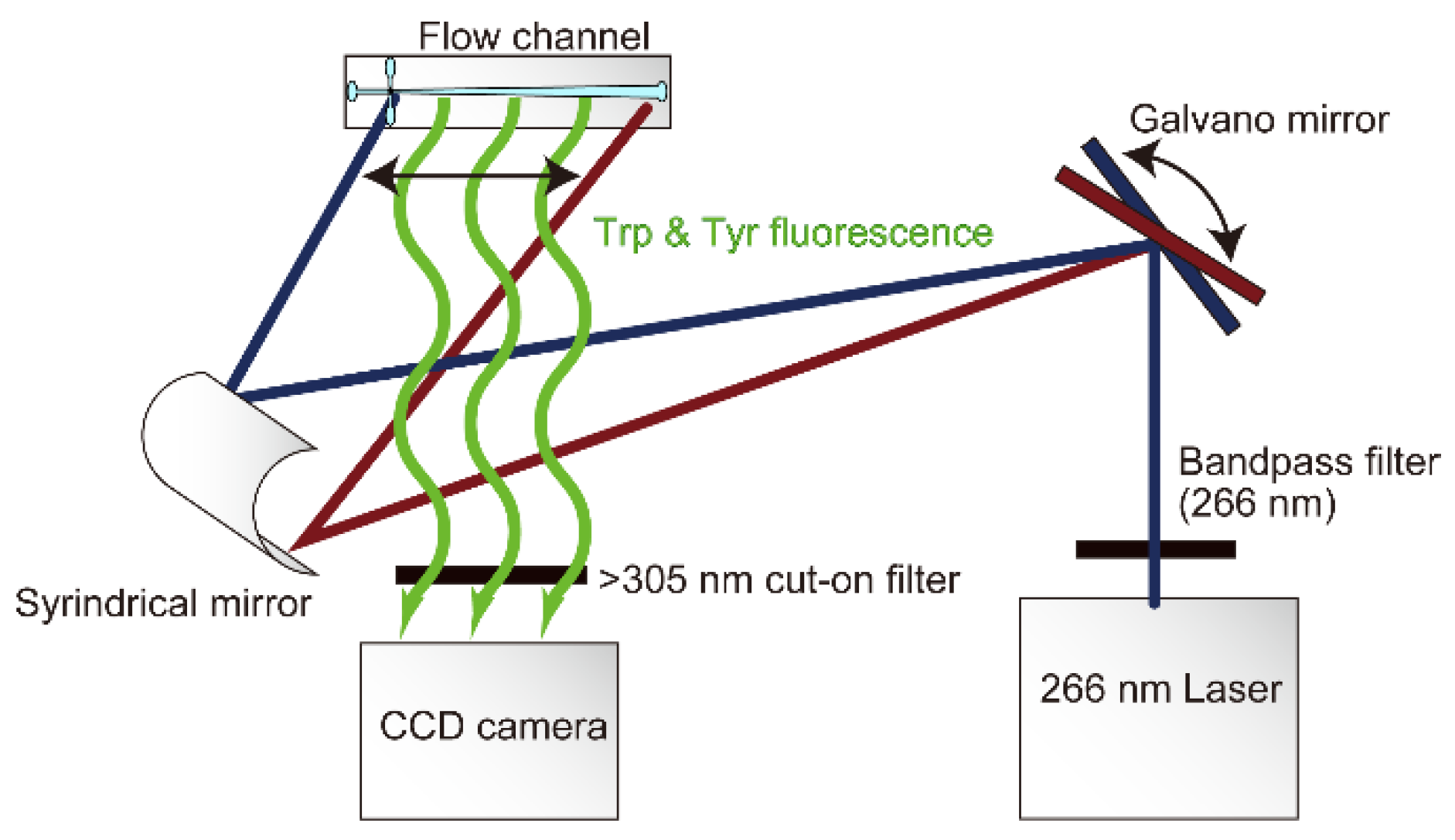
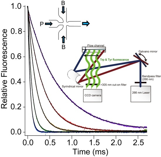
In previous laser-based continuous-flow instruments, the laser was focused on the flow channel and reaction progress was sampled point by point downstream from the mixing region [9,10,24,25]. Generating a complete kinetic trace using this approach requires dozens of separate measurements while maintaining continuous-flow conditions for extended periods of time, consuming large amounts of reagents. In contrast, we used a pair of Galvano mirrors and a cylindrical mirror to focus the laser onto the flow channel and control its position (Figure 2). The mirrors are regulated to scan the length of the flow channel using a triangular wave function, resulting in uniform distribution of light intensity vs. distance over a 23 mm segment of the channel. As in our original setup (Figure 1A), a quartz lens (f = 3.5 mm) and 305 nm high-pass interference filter (Semrock, Rochester, NY, USA) are used to project a magnified image of the flow channel onto a CCD detector (Figure 2). Thus, in a single continuous-flow experiment typically lasting 10 s (including a ~3 s acceleration time prior to activating the CCD camera), we can record a complete trace of fluorescence emission vs. time after mixing over the time range from td (~10 µs) to tmax (~2.5 ms) with an effective time resolution of ~1 µs in the narrow portion of the observation channel near the mixing region and ~4 µs near the end. We found empirically that a scanning frequencies of 20 Hz is optimal for achieving stable and uniform fluorescence excitation. This scan rate is negligibly slow compared to the pulse repetition rate of the laser but fast compared to the exposure times of ~10 s typically used in continuous-flow experiments. Thus, this novel excitation scheme is equivalent to continuous-wave illumination using a conventional light source but achieves more uniform and intense fluorescence excitation.

2.4. Data Collection and Analysis

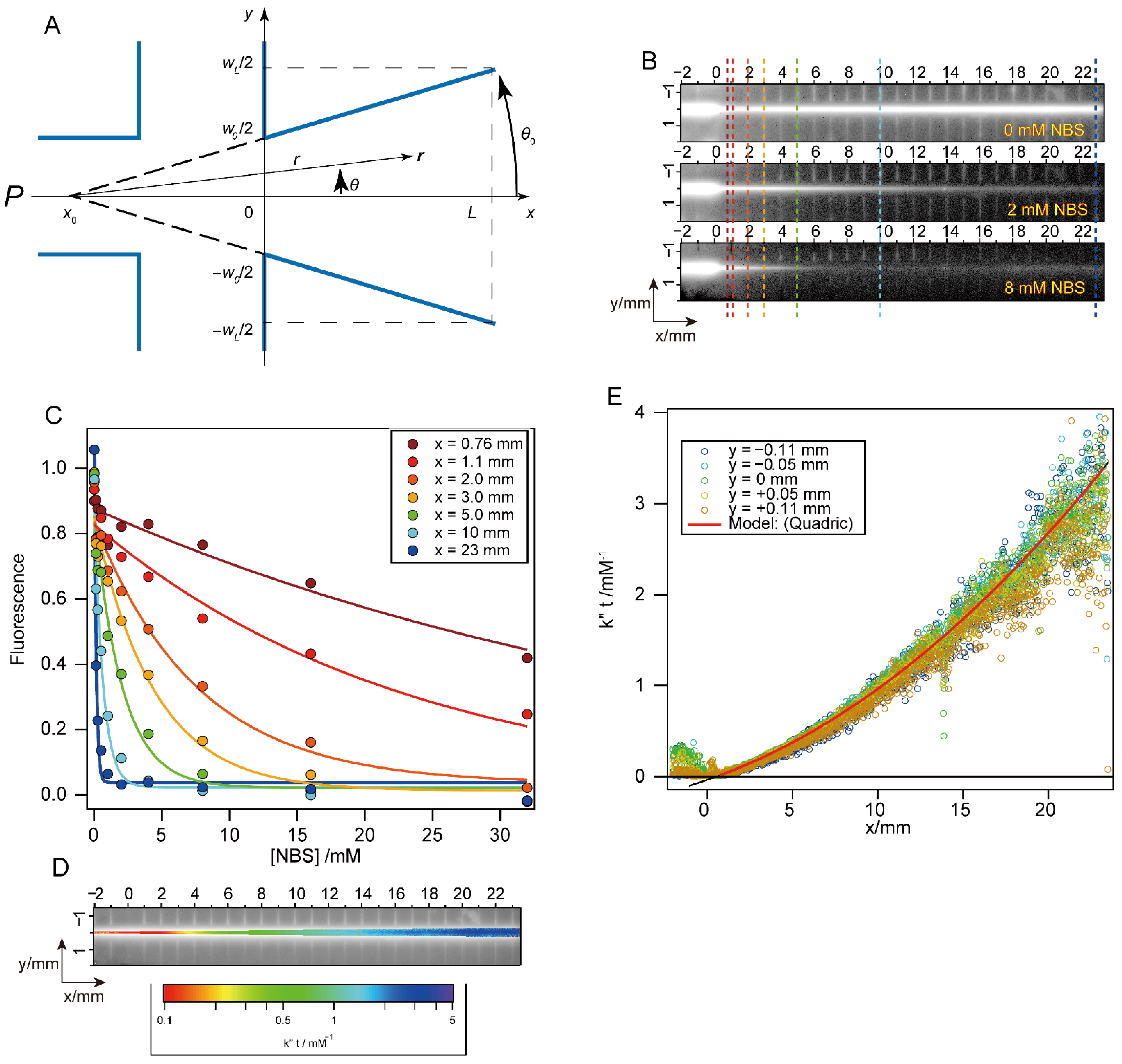
The procedures for data collection and analysis using Mixer 3 are similar to those described by Shastry et al. [8], except for the calculation of the time axis. Because of the conical shape of the flow channel of Mixer 3, the reaction time at constant flow rate is no longer a linear function of the distance from the mixing region. At the flow rates typically used (0.5–1 mL/s), we estimate Reynolds numbers Re of 2300–4500, corresponding to moderately to strongly turbulent flow conditions. In this case, wall effects can be neglected, and the flow velocity profile, v(r), can be approximately described as a 2-dimensional radial function of the position, r(r, θ), within the widening flow channel of constant depth (Figure 3):
v r = V 2 θ 0 d r 2 r ,
where V, θ0, d, r and θ are the volume velocity, opening angle of channel, channel depth and the magnitude and angle of the pointing vector r, respectively (Figure 3A). Using Cartesian coordinate system with origin placed at the exit of the mixing region, the reaction time tr at each point is represented as follows:
t r = θ 0 d V ( ( x x 0 ) 2 + y 2 ) = θ 0 d V ( 1 + t a n 2 θ ) ( x x 0 ) 2 ,
where x0 is the position of the virtual vertex of the cone and t a n θ = y / x x 0 ; thus, −θ0 < θ < θ0. Given the shallow open angle of the channel, t a n 2 θ is neglected (~7 × 10⁻⁵), and thus tr is effectively a function of x only. As a result, the position dependence of tr simplifies to:
t r x d V w L w 0 2 L x 2 + w 0 x + t ,
where wL and w0 are the channel width at x = L and 0, respectively, and Δt is the mixing time. The first term is consistent with the time required to fill the volume between [0, x] at constant flow rate V.
To confirm the validity of Equation (3) for describing the nonlinear time axis of Mixer 3, we measured the quenching reaction of NAT fluorescence in the presence of excess NBS (Figure 3B). The kinetics of this pseudo first-order reaction is given by:
f t , N B S f 0 e x p k N B S t ,
where f0 is the initial fluorescence intensity, and k″ is the second-order rate constants. Normally, the time course of reaction is analyzed by fitting to a single-exponential function at a fixed NBS concentration to obtain the apparent rate constant, k″[NBS]. In contrast, we evaluate Equation (4) at a fixed time (or a fixed pixel position) and variable NBS concentration (125 μM to 32 mM) in order to estimate kt (Figure 3C,D). The kt values obtained were a quadratic function of x, as predicted by Equation (3) (Figure 3E), thus confirming the validity of the underlying approximation. On the basis of the scatter of the points in panel E, we estimate that the error of the time-axis calibration is 0.3% at the earliest time points and 4% at long times.

2.5. Optimization of Mixing Conditions

Key considerations in optimizing mixing efficiency and performance are mixing ratio and flow rate. Higher mixing ratios are desirable for achieving large changes in solvent conditions but require more concentrated stock solutions, which may be limited by solubility. First, we used the NAT-NBS reaction to estimate the dead time of Mixer 3 at constant flow rate (0.7 mL/s) and variable mixing ratios (Figure 4A). The shortest dead time, 12 μs, was obtained when mixing 1 part of solution P (center port) with 10 parts of solution B (side ports; see Figure 1). Thus, Mixer 3 shows the best performance when reactions are initiated by a large concentration jump, which was one of our design criteria. Interestingly, the second-best dead time, 17 μs, was obtained for 1:1 mixing. With respect to flow rate optimization, higher flow velocities are expected to produce more turbulent flow in the mixing region, resulting in improved mixing efficiency and shorter dead times, although this comes at the cost of higher consumption of reagents and a shortened observation window. However, further increases in flow rate not only lead to a sharp increase in backpressure but may also give rise to light scattering artifacts due to cavitation, i.e., bubble formation due to the large pressure drop below the mixing region. By measuring the NAT-NBS reaction at different flow rates (1:10 mixing ratio), we found that the dead time of Mixer 3 decreases sharply with increasing flow rate, reaching values of about 20 μs at 0.7 mL/s to 1.0 mL/s. Under these conditions, we expect turbulent flow, based on estimated Reynolds numbers (3200 to 4500). At flow rates of 0.7 mL/s and above, the apparent rate of the NAT-NBS reaction increases linearly with NBS concentration up to 32 mM, as expected for a second-order reaction (Figure 4C). However, at flow rates less than 0.7 mL/s, the apparent rates at high NBS concentrations fall below those expected for a second-order reaction, indicating that the observed kinetics is increasingly limited by the rate of mixing under these sub-optimal flow conditions (Reynolds numbers less than 2400). In summary, optimal performance of Mixer 3, including dead times of 20 μs or less and a time window extending out to 2 to 3 ms, is achieved by using a mixing ratio of 1:10 and flow rates of 0.7 to 1.0 mL/s.

2.6. Mixing Efficiency

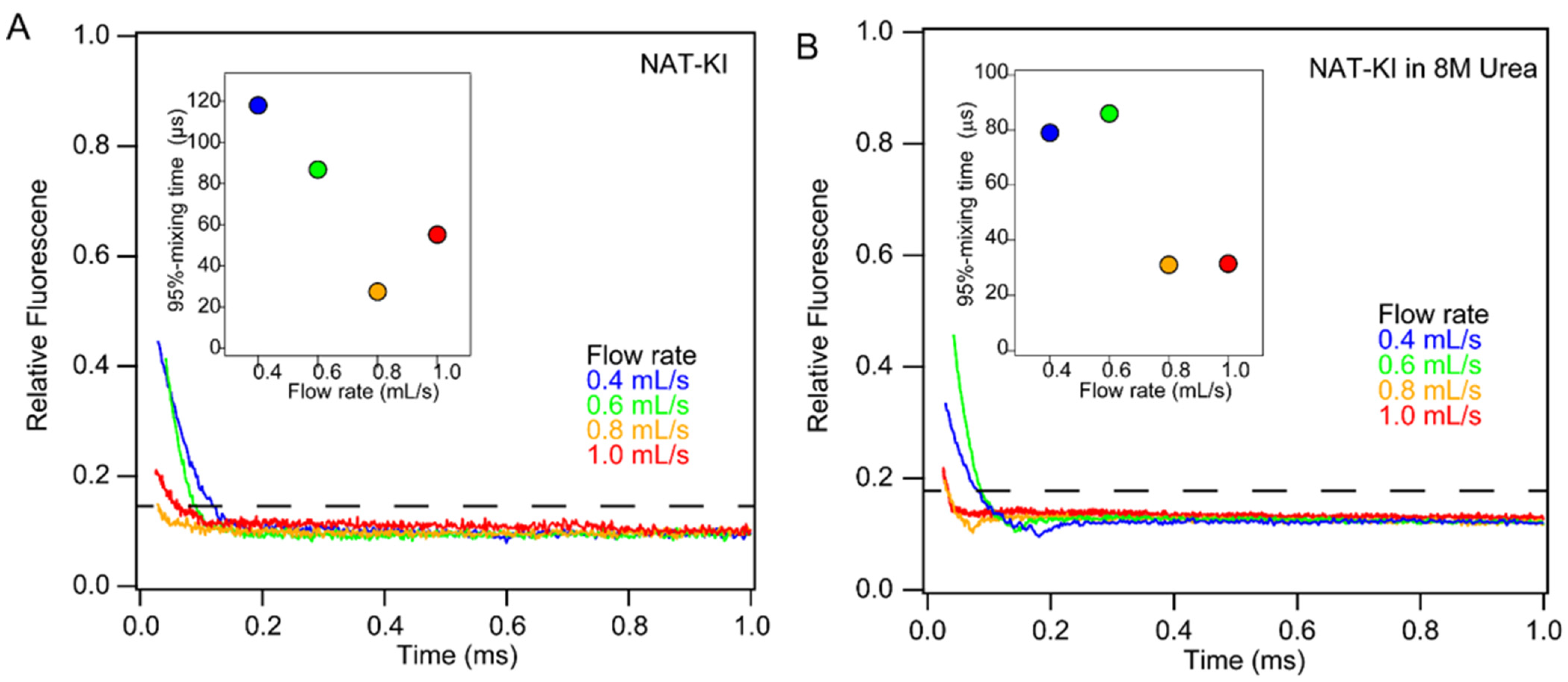
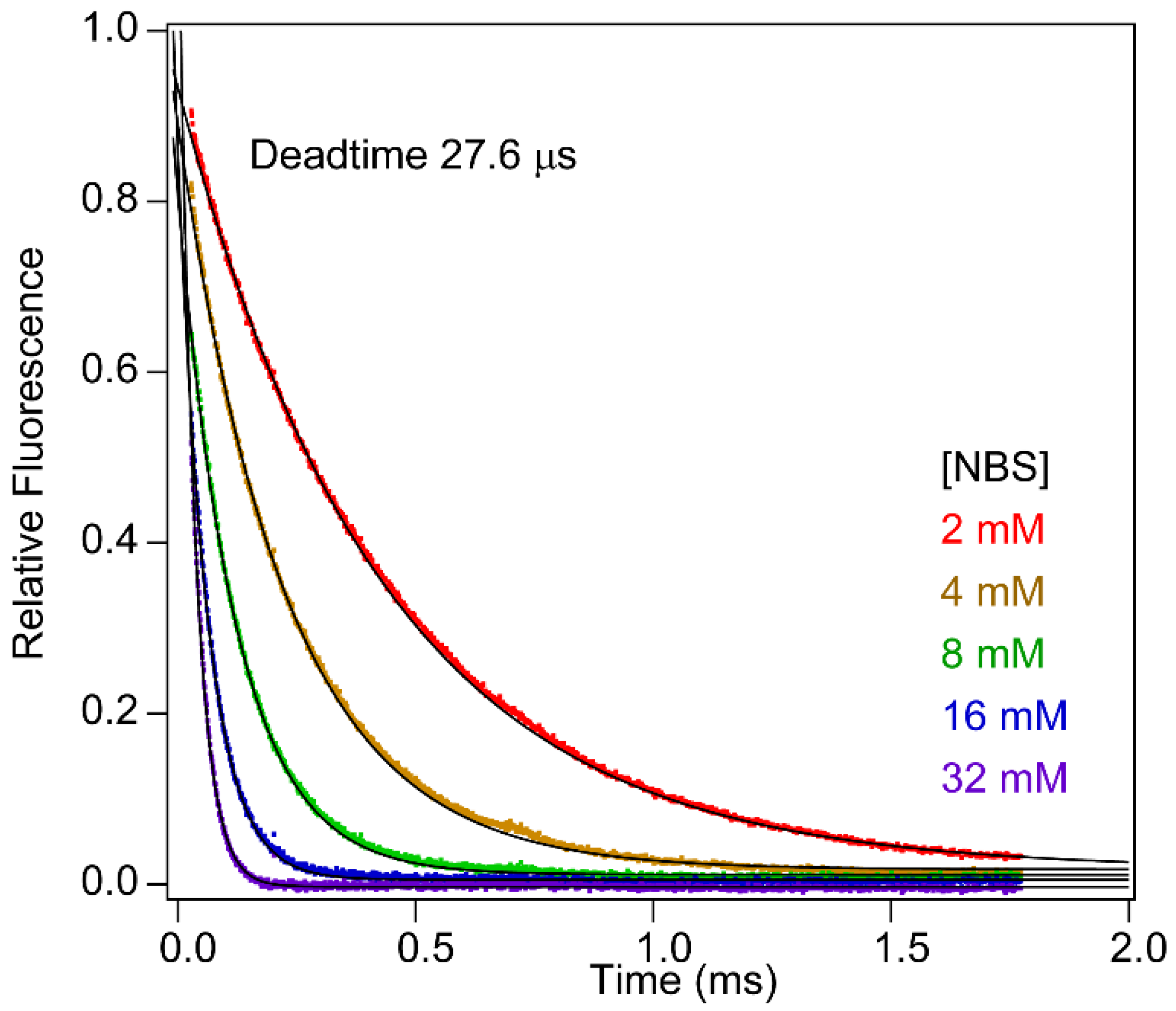
To quantify mixing efficiency, we relied on the quenching of NAT fluorescence by potassium iodide (Figure 5A). This collisional quenching process is fast compared to the time scale of mixing, and quenching efficiency is concentration-dependent (90% at 1 mM potassium iodide). Thus, the normalized decrease in NAT fluorescence upon mixing with iodide provides a direct measure of mixing efficiency. At a flow rate of 0.8 mL/s, the fluorescence intensity dropped to 14% of the original value at the first observable data point after the mixing region, indicating that the mixing efficacy is ~96%. At lower flow rates (0.6 and 0.4 mL/s), the residual fluorescence was much higher and decayed more slowly, resulting in substantially longer dead times (≥100 µs). At a flow rate of 1.0 mL/s, the initial fluorescence was slightly higher compared to 0.8 mL/s, most likely due to the onset of cavitation and concomitant light scattering artifacts. We also performed mixing efficiency tests in the presence of 8 M urea, which is commonly used in protein unfolding and refolding experiments (Figure 5B). The iodide quenching profiles obtained were similar to those in the absence of urea, indicating that high concentrations of urea do not impair mixing efficiency. This was confirmed by measuring the dead time, using the NAT-NBS reaction in the presence of 16.2% sucrose with viscosity matching that of an 8 M urea solution (note that NBS reacts with urea). To mimic conditions of a typical protein unfolding experiment, an aqueous solution of NAT was mixed with 10-fold excess of NBS dissolved in 17.9% sucrose, yielding a final concentration of 16.2%. As expected, the increase in viscosity results in a somewhat longer dead time (27 μs), but mixing efficiency remains high and mixing artifacts negligible even when mixing solutions of widely differing density and viscosity (Figure 6).

2.7. Accuracy

To assess the accuracy of the kinetics data obtained by Mixer 3, we measured the second-order rate, k″, of the NAT-NBS reaction by measuring the observed rate constant vs. NBS concentration under pseudo-first-order conditions (Figure 1C). The observed k″ of 1.2 × 10⁶ M−1 s−1 is in excellent agreement with that measured previously using a capillary mixer (Figure 1A). Taken together, these test results confirm that our microfluidic mixer design allows accurate and reliable measurements of rate constants as fast as ~105 s−1.

3. Applications

3.1. Folding of Cytochrome c

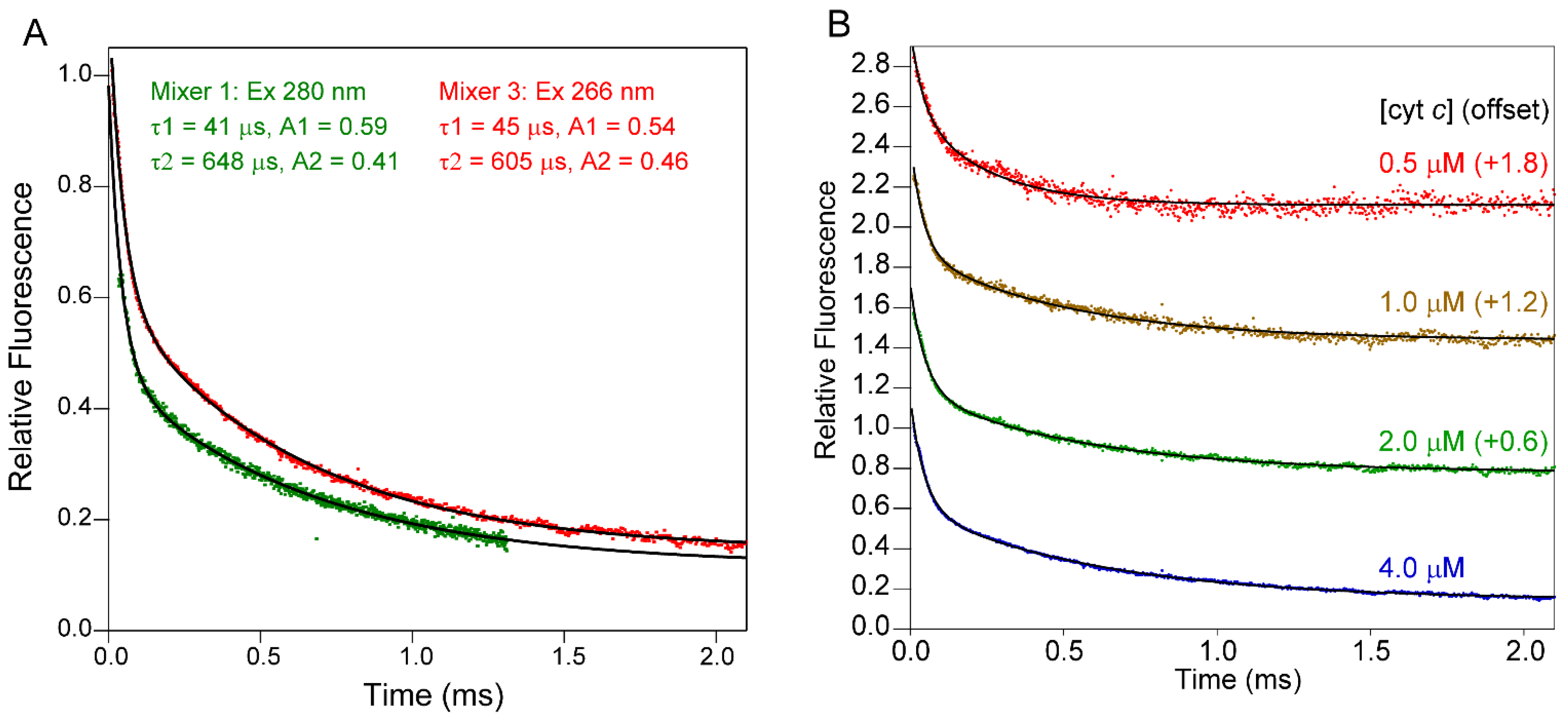
As a first application of our improved continuous-flow setup, we used Mixer 3 to monitor early stages of folding of cytochrome c (cyt c), which has long served as a test case for the development of new methodologies [4,5,31,32,55,56]. Horse cyt c is a 104-residue protein with a covalently attached heme group. The fluorescence of its sole tryptophan residue, Trp59, is governed by Förster energy transfer interaction with the heme, resulting in complete quenching in the folded state [57]. Prior studies using commercial stopped-flow instruments with a dead time of 1 ms or longer showed that the fluorescence change upon refolding accounts for at most 15% of the total fluorescence change, indicating that major conformational changes occur on the sub-millisecond time scale [58]. The development of a capillary mixing apparatus with a dead time of ~40 µs [8] made it possible to resolve the entire fluorescence change associated with the refolding of acid-denatured cyt c triggered by a jump in pH from 2.0 to 4.5, including a major phase with time constant τ1 = 41 μs accounting for 59% of the amplitude and a second phase with time constant τ2 = 648 μs accounting for 41% of the amplitude (green trace in Figure 7A; c.f. [32]). When we repeated this experiment using Mixer 3 (red trace), we also observed a biphasic decay in fluorescence with identical (within error) time constants (τ1 = 45 μs, τ2 = 605 μs) and similar amplitudes (A1 = 0.54 and A2 = 0.46). Minor differences in the amplitudes of the kinetic traces obtained with our new setup (Figure 1C) compared to the previous configuration (Figure 1A) can be explained by the fact that the ratio of tryptophan vs. tyrosine fluorescence excitation is lower at the wavelength of the UV laser (266 nm) compared to that used previously (280 nm). In both cases, a double-exponential fit accurately describes the observed fluorescence decay, and the extrapolated value at t = 0 is within ±5% the fluorescence of the acid-unfolded initial state, indicating that we are able to resolve the complete time course of folding associated with changes in intrinsic fluorescence. To document reproducibility, we compared the kinetic traces obtained in four independent experiments. The mean values and standard deviations for the corresponding kinetic parameters were as follows: <τ1> = 51 ± 14 μs; <A1> = 0.55 ± 0.09; <τ2> = 602 ± 51 μs; <A2> = 0.39 ± 0.05.
We have previously attributed the fast phase during refolding of cyt c in terms of a barrier-limited collapse of the polypeptide chain, based on its large amplitude consistent with a major decrease in average distance between the covalently attached heme and Trp59, as well as the temperature dependence of its rate constant indicative of a small but significant activation energy [32,33,59]. In a more recent study, using a microfluidic mixer to perform quenched H/D exchange measurements on the sub-millisecond time scale, we found that amide groups in two α-helices in the C-terminal half of cyt c were partially protected already during the fast (40 μs) phase, indicating that the initial compaction of the polypeptide chain involved formation of short-range helix–helix contacts, and is thus inconsistent with a random polymer collapse [60]. Helical structure in the N-terminal region begins to appear only during the second (600 μs) folding phase, suggesting that long-range tertiary contacts are established during the later stages of folding. Mitic et al. recently used an absorbance-detected continuous-flow mixing setup with a 4 µs dead time to monitor the kinetics of refolding of acid-denatured cyt c [11]. In addition to two kinetic phases with time constants similar to those of our two fluorescence-detected phases (83 and 345 μs, respectively), Mitic et al. observed an additional process with a time constant of 4.7 μs they attribute to binding of the His18 side chain to the initially four-coordinated heme iron. Because the heme group is covalently linked to the protein via thioester linkages to Cys 14 and Cys 17, this is a local conformational event not expected to be associated with a change in Trp59 fluorescence.
In addition to documenting the fact that the kinetic data obtained using Mixer 3 are fully consistent with those obtained previously using Mixer 1, Figure 7A also indicates a major improvement in the signal-to-noise ratio (S/N) and data quality. Our new excitation scheme using a 266 nm UV laser in combination with a set of Galvano mirrors (Figure 2) resulted in a high-quality kinetic trace with ~2-fold higher S/N on a 4 μM cyt c solution compared to that measured previously at a fivefold higher protein concentration using a Hg-Xe arc lamp and monochromator tuned to 280 nm. By repeating these experiments at several lower cyt c concentrations, we obtained reproducible kinetic traces with acceptable S/N down to protein concentrations as low as 0.5 μM (Figure 7B). Even though the 266 nm laser is suboptimal in terms of excitation of tryptophan fluorescence, comparison with the data obtained previously using 280 nm excitation (green trace in Figure 7A) indicates that our redesigned optical configuration has resulted in a ~20-fold increase in S/N.

3.2. Binding of a Peptide Ligand to a PDZ Domain

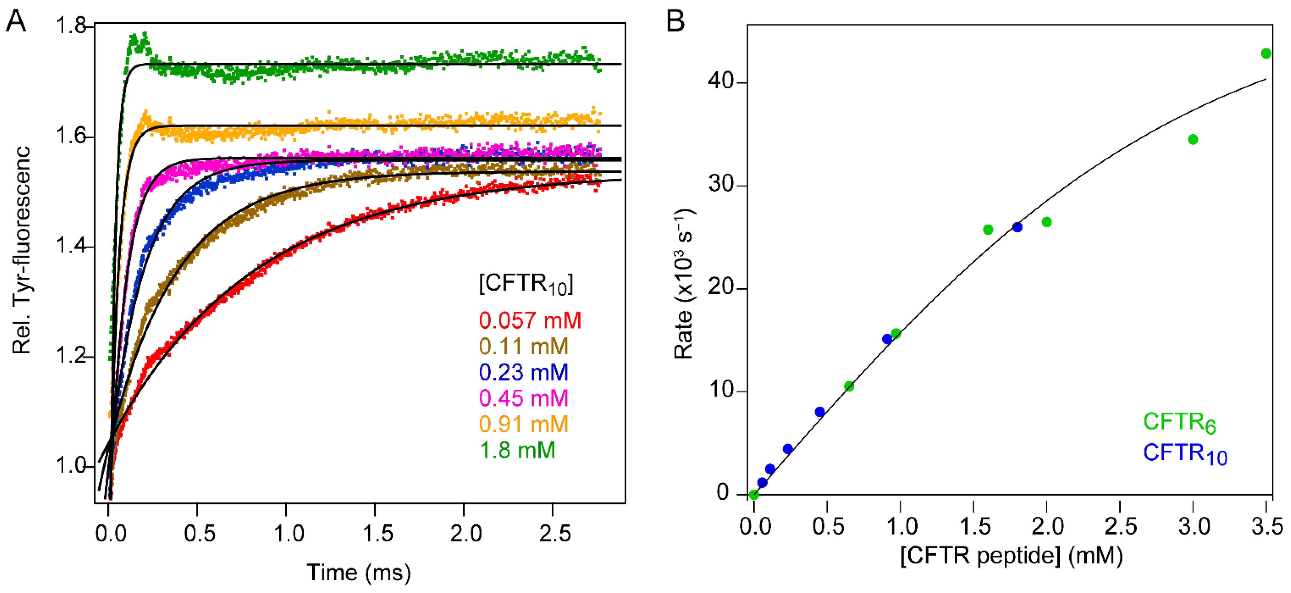
Rapid mixing methods have also played a central role in mechanistic studies of protein–ligand interactions. If ligand binding is coupled with a change in protein conformation, one can envision two limiting mechanisms, depending on whether the second-order binding step precedes the conformational change (“induced fit”) or occurs after formation of a binding-competent conformation (“conformational selection”). Both scenarios have been documented for different systems [61,62] or even for the same protein–ligand pair under different conditions [63,64]. One approach for distinguishing between these mechanisms is to measure the kinetics of binding as a function of either ligand or protein concentration [62]. The difference in predicted kinetics is especially pronounced at high ligand (or protein) concentrations where rate constants often exceed 1000 s−1 and thus require instrumentation for ultra-fast mixing [39]. As an illustrative example, we show in Figure 8 the kinetics of binding of a cognate peptide ligand to the first PDZ domain of NHERF1/EBP50 [65], a signaling adaptor at the membrane–cytoskeleton interface comprising a pair of PDZ domains and a C-terminal ezrin-binding motif. High-affinity binding of the ligand peptides studied here, CFTR6 (Ac-VQDTRL) and CFTR10 (Ac-TEEEVQDTRL), derived from the C-terminus of the cystic fibrosis transmembrane conductance regulator (CFTR), is primarily mediated by interactions of the C-terminal DTRL motif with a deep groove on the surface the PDZ domain [66].
To follow the time course of binding as a function of peptide concentration, we monitored the ligand-induced change in fluorescence of a tyrosine residue located in a pocket recognizing the C-terminal leucine of the CFTR peptide (Figure 8A). The rate constants observed under pseudo-first-order conditions increased sharply with increasing peptide concentration, reaching a value of 43,000 ± 3000 s−1 (τ = 23 μs) at 3.5 mM (Figure 8B). The results document the ability of our instrument to resolve changes in inherently weak tyrosine fluorescence on the 10 μs time scale. Initially, the observed rate constant increases linearly with peptide concentration but begins to level off somewhat at concentrations above 1 mM. This behavior is intermediate between the strongly hyperbolic concentration dependence reported for PTP-BL PDZ2 and the strictly linear dependence on ligand concentration found for PSD-95 PDZ3 [39], indicating that these structurally closely related protein–ligand pairs experience different degrees of conformational changes and exhibit a surprising range of kinetic properties.

4. Conclusions

We have described the design and testing of an instrument for continuous-flow fluorescence measurements on the microsecond-to-millisecond time scale that combines a highly efficient microfluidic mixer/flow cell assembly on a quartz chip with a novel laser-scanning scheme for enhanced fluorescence excitation. The instrument features several performance characteristics that are critical for routine application to the ultrafast kinetic analysis of biomolecular folding and binding reactions. The dead time of 12 μs we measured under optimal flow conditions at low viscosity is at or near the low end of the fluorescence-based rapid mixing devices reported in the literature. Mixing efficiency remains high even under more viscous conditions, which is essential for studies of denaturant-induced protein folding or unfolding reactions. Further reductions in mixer and channel dimensions have been reported to result in somewhat shorter dead times, but this comes at the cost of major increases in backpressure and sample concentration. In contrast, by combining a tapered observation channel with a novel Galvano-mirror laser-scanning strategy, our instrument yields high-quality kinetic traces ranging from tens of microseconds to several milliseconds on protein concentrations as low as 1 µM. Representative kinetic data on early events during folding of cytochrome c and binding of a peptide ligand to a PDZ domain illustrate the power of the method for exploring the dynamics of macromolecular folding and binding reactions.

Author Contributions

Conceptualization, T.M. and H.R.; methodology, T.M. and H.R.; software, T.M.; testing and validation, T.M.; data analysis, T.M.; resources, H.R.; writing—original draft preparation, T.M.; writing—review and editing, H.R. and T.M.; visualization, T.M.; project administration, H.R.; funding acquisition, H.R. All authors have read and agreed to the published version of the manuscript.

Funding

This research was funded by the National Institutes of Health, grant number GM116911 (to H.R.), and a Cancer Center Support Grant from the National Cancer Institute (CA06927).

Institutional Review Board Statement

Not applicable.

Informed Consent Statement

Not applicable.

Data Availability Statement

Not applicable.

Conflicts of Interest

The authors declare no conflict of interest. The funders had no role in the design of the study; in the collection, analyses or interpretation of data; in the writing of the manuscript or in the decision to publish the results.

Appendix A

Figure A1. Detailed schematic of the layout of Mixer 3, including dimensions (in mm). (A) Overview of the quartz chip. Channel depth is 0.25 mm. (B) Expanded diagram of the mixing region at the intersection of the cross-channels.
Molecules 27 03392 g0a1

References

  1. Gruebele, M.; Sabelko, J.; Ballew, R.; Ervin, J. Laser temperature jump induced protein folding. Acc. Chem. Res. 1998, 31, 699–707. [Google Scholar] [CrossRef]
  2. Dyer, R.B.; Brauns, E.B. Laser-induced temperature jump infrared measurements of RNA folding. Methods Enzymol. 2009, 469, 353–372. [Google Scholar] [PubMed] [Green Version]
  3. Prigozhin, M.B.; Liu, Y.; Wirth, A.J.; Kapoor, S.; Winter, R.; Schulten, K.; Gruebele, M. Misplaced helix slows down ultrafast pressure-jump protein folding. Proc. Natl. Acad. Sci. USA 2013, 110, 8087–8092. [Google Scholar] [CrossRef] [PubMed] [Green Version]
  4. Jones, C.M.; Henry, E.R.; Hu, Y.; Chan, C.-K.; Luck, S.D.; Bhuyan, A.; Roder, H.; Hofrichter, J.; Eaton, W.A. Fast events in protein folding initiated by nanosecond laser photolysis. Proc. Natl. Acad. Sci. USA 1993, 90, 11860–11864. [Google Scholar] [CrossRef] [Green Version]
  5. Pascher, T.; Chesick, J.P.; Winkler, J.R.; Gray, H.B. Protein folding triggered by electron transfer. Science 1996, 271, 1558–1560. [Google Scholar] [CrossRef] [PubMed]
  6. Knight, J.B.; Vishwanath, A.; Brody, J.P.; Austin, R.H. Hydrodynamic focusing on a silicon chip: Mixing nanoliters in microseconds. Phys. Rev. Lett. 1998, 80, 3863–3866. [Google Scholar] [CrossRef]
  7. Lapidus, L.J.; Yao, S.; McGarrity, K.S.; Hertzog, D.E.; Tubman, E.; Bakajin, O. Protein hydrophobic collapse and early folding steps observed in a microfluidic mixer. Biophys. J. 2007, 93, 218–224. [Google Scholar] [CrossRef] [Green Version]
  8. Shastry, M.C.R.; Luck, S.D.; Roder, H. A continuous-flow capillary mixer to monitor reactions on the microsecond time scale. Biophys. J. 1998, 74, 2714–2721. [Google Scholar] [CrossRef] [Green Version]
  9. Chan, C.-K.; Hu, Y.; Takahashi, S.; Rousseau, D.L.; Eaton, W.A.; Hofrichter, J. Submillisecond protein folding kinetics studied by ultrarapid mixing. Proc. Natl. Acad. Sci. USA 1997, 94, 1779–1784. [Google Scholar] [CrossRef] [Green Version]
  10. Bilsel, O.; Kayatekin, C.; Wallace, L.A.; Matthews, C.R. A microchannel solution mixer for studying microsecond protein folding reactions. Rev. Sci. Instr. 2005, 76, 014302. [Google Scholar] [CrossRef]
  11. Mitic, S.; Strampraad, M.J.F.; Hagen, W.R.; de Vries, S. Microsecond time-scale kinetics of transient biochemical reactions. PLoS ONE 2017, 12, e0185888. [Google Scholar] [CrossRef] [PubMed] [Green Version]
  12. DeCamp, S.J.; Naganathan, A.N.; Waldauer, S.A.; Bakajin, O.; Lapidus, L.J. Direct observation of downhill folding of lambda-repressor in a microfluidic mixer. Biophys. J. 2009, 97, 1772–1777. [Google Scholar] [CrossRef] [PubMed] [Green Version]
  13. Roder, H.; Maki, K.; Cheng, H.; Shastry, M.C. Rapid mixing methods for exploring the kinetics of protein folding. Methods 2004, 34, 15–27. [Google Scholar] [CrossRef] [PubMed]
  14. Roder, H.; Maki, K.; Cheng, H. Early events in protein folding explored by rapid mixing methods. Chem. Rev. 2006, 106, 1836–1861. [Google Scholar] [CrossRef] [PubMed]
  15. Kathuria, S.V.; Guo, L.; Graceffa, R.; Barrea, R.; Nobrega, R.P.; Matthews, C.R.; Irving, T.C.; Bilsel, O. Minireview: Structural insights into early folding events using continuous-flow time-resolved small-angle X-ray scattering. Biopolymers 2011, 95, 550–558. [Google Scholar] [CrossRef]
  16. Tonomura, B.; Nakatani, H.; Ohnishi, M.; Yamaguchi-Ito, J.; Hiromi, K. Test reactions for a stopped-flow apparatus. Reduction of 2,6-dichlorophenolindophenol and potassium ferricyanide by L-ascorbic acid. Anal. Biochem. 1978, 84, 370–383. [Google Scholar] [CrossRef]
  17. Brissette, P.; Ballou, D.P.; Massey, V. Determination of the dead time of a stopped-flow fluorometer. Anal. Biochem. 1989, 181, 234–238. [Google Scholar] [CrossRef] [Green Version]
  18. Chance, B. Accelerated and stopped-flow apparatus. II. J. Franklin Inst. 1940, 220, 455–613. [Google Scholar] [CrossRef]
  19. Gibson, Q.H.; Milnes, L. Apparatus for rapid and sensitive spectrophotometry. Biochem. J. 1964, 91, 161–171. [Google Scholar] [CrossRef] [Green Version]
  20. Berger, R.L.; Balko, B.; Borcherdt, W.; Friauf, W. High speed optical stopped-flow apparatus. Rev. Sci. Instrum. 1968, 39, 486–493. [Google Scholar] [CrossRef]
  21. Chance, B. Rapid Mixing and Sampling Techniques in Biochemistry; Academic Press: New York, NY, USA, 1964. [Google Scholar]
  22. Moskowitz, G.W.; Bowman, R.L. Muliticaplillary mixer of solutions. Science 1966, 153, 428–429. [Google Scholar] [CrossRef] [PubMed]
  23. Regenfuss, P.; Clegg, R.M.; Fulwyler, M.J.; Barrantes, F.J.; Jovin, T.M. Mixing liquids in microseconds. Rev. Sci. Instrum. 1985, 56, 283–290. [Google Scholar] [CrossRef]
  24. Paeng, K.; Paeng, I.; Kincaid, J. Time-resolved resonance raman spectroscopy using a fast mixing device. Anal. Sci. 1994, 10, 157–159. [Google Scholar] [CrossRef] [Green Version]
  25. Takahashi, S.; Ching, Y.-c.; Wang, J.; Rousseau, D.L. Microsecond generation of oxygen-bound cytochrome c oxidase by rapid solution mixing. J. Biol. Chem. 1995, 270, 8405–8407. [Google Scholar] [CrossRef] [Green Version]
  26. Akiyama, S.; Takahashi, S.; Ishimori, K.; Morishima, I. Stepwise formation of alpha-helices during cytochrome c folding. Nat. Struct Biol. 2000, 7, 514–520. [Google Scholar] [CrossRef]
  27. Matsumoto, S.; Yane, A.; Nakashima, S.; Hashida, M.; Fujita, M.; Goto, Y.; Takahashi, S. A rapid flow mixer with 11-mus mixing time microfabricated by a pulsed-laser ablation technique: Observation of a barrier-limited collapse in cytochrome c folding. J. Am. Chem. Soc. 2007, 129, 3840–3841. [Google Scholar] [CrossRef]
  28. Jiang, L.; Zeng, Y.; Sun, Q.; Sun, Y.; Guo, Z.; Qu, J.Y.; Yao, S. Microsecond protein folding events revealed by time-resolved fluorescence resonance energy transfer in a microfluidic mixer. Anal. Chem. 2015, 87, 5589–5595. [Google Scholar] [CrossRef]
  29. Inguva, V.; Kathuria, S.V.; Bilsel, O.; Perot, B.J. Computer design of microfluidic mixers for protein/RNA folding studies. PLoS ONE 2018, 13, e0198534. [Google Scholar] [CrossRef] [Green Version]
  30. Liu, C.; Li, Y.; Liu, B.F. Micromixers and their applications in kinetic analysis of biochemical reactions. Talanta 2019, 205, 120136. [Google Scholar] [CrossRef]
  31. Takahashi, S.; Yeh, S.-R.; Das, T.K.; Chan, C.-K.; Gottfried, D.S.; Rousseau, D.L. Folding of cytochrome c initiated by submillisecond mixing. Nat. Struct. Biol. 1997, 4, 44–50. [Google Scholar] [CrossRef]
  32. Shastry, M.C.R.; Roder, H. Evidence for barrier-limited protein folding kinetics on the microsecond time scale. Nat. Struct. Biol. 1998, 5, 385–392. [Google Scholar] [CrossRef] [PubMed]
  33. Shastry, M.C.R.; Sauder, J.M.; Roder, H. Kinetic and structural analysis of submillisecond folding events in cytochrome c. Acc. Chem. Res. 1998, 31, 717–725. [Google Scholar] [CrossRef]
  34. Park, S.-H.; Shastry, M.C.R.; Roder, H. Folding dynamics of the B1 domain of protein G explored by ultrarapid mixing. Nat. Struct. Biol. 1999, 6, 943–947. [Google Scholar] [CrossRef] [PubMed]
  35. Capaldi, A.P.; Shastry, R.M.C.; Kleanthous, C.; Roder, H.; Radford, S.E. Ultra-rapid mixing experiments reveal that Im7 folds via an on-pathway intermediate. Nat. Struct. Biol. 2001, 8, 68–72. [Google Scholar] [PubMed]
  36. Teilum, K.; Maki, K.; Kragelund, B.B.; Poulsen, F.M.; Roder, H. Early kinetic intermediate in the folding of acyl-CoA binding protein detected by fluorescence labeling and ultrarapid mixing. Proc. Natl. Acad. Sci. USA 2002, 99, 9807–9812. [Google Scholar] [CrossRef] [PubMed] [Green Version]
  37. Maki, K.; Cheng, H.; Dolgikh, D.A.; Shastry, M.C.; Roder, H. Early Events During Folding of Wild-type Staphylococcal Nuclease and a Single-tryptophan Variant Studied by Ultrarapid Mixing. J. Mol. Biol. 2004, 338, 383–400. [Google Scholar] [CrossRef]
  38. Uzawa, T.; Akiyama, S.; Kimura, T.; Takahashi, S.; Ishimori, K.; Morishima, I.; Fujisawa, T. Collapse and search dynamics of apomyoglobin folding revealed by submillisecond observations of α-helical content and compactness. Proc. Natl. Acad. Sci. USA 2004, 101, 1171–1176. [Google Scholar] [CrossRef] [Green Version]
  39. Gianni, S.; Walma, T.; Arcovito, A.; Calosci, N.; Bellelli, A.; Engstrom, A.; Travaglini-Allocatelli, C.; Brunori, M.; Jemth, P.; Vuister, G.W. Demonstration of long-range interactions in a PDZ domain by NMR, kinetics, and protein engineering. Structure 2006, 14, 1801–1809. [Google Scholar] [CrossRef] [Green Version]
  40. Maki, K.; Cheng, H.; Dolgikh, D.A.; Roder, H. Folding kinetics of staphylococcal nuclease studied by tryptophan engineering and rapid mixing methods. J. Mol. Biol. 2007, 368, 244–255. [Google Scholar] [CrossRef] [PubMed] [Green Version]
  41. Apetri, A.C.; Maki, K.; Roder, H.; Surewicz, W.K. Early intermediate in human prion protein folding as evidenced by ultrarapid mixing experiments. J. Am. Chem. Soc. 2006, 128, 11673–11678. [Google Scholar] [CrossRef] [Green Version]
  42. Arai, M.; Kondrashkina, E.; Kayatekin, C.; Matthews, C.R.; Iwakura, M.; Bilsel, O. Microsecond hydrophobic collapse in the folding of Escherichia coli dihydrofolate reductase, an alpha/beta-type protein. J. Mol. Biol. 2007, 368, 219–229. [Google Scholar] [CrossRef] [PubMed]
  43. Chen, K.C.; Xu, M.; Wedemeyer, W.J.; Roder, H. Microsecond unfolding kinetics of sheep prion protein reveals an intermediate that correlates with susceptibility to classical scrapie. Biophys. J. 2011, 101, 1221–1230. [Google Scholar] [CrossRef] [PubMed] [Green Version]
  44. Xu, M.; Beresneva, O.; Rosario, R.; Roder, H. Microsecond folding dynamics of apomyoglobin at acidic pH. J. Phys. Chem. B 2012, 116, 7014–7025. [Google Scholar] [CrossRef] [PubMed] [Green Version]
  45. Mizukami, T.; Xu, M.; Cheng, H.; Roder, H.; Maki, K. Nonuniform chain collapse during early stages of staphylococcal nuclease folding detected by fluorescence resonance energy transfer and ultrarapid mixing methods. Protein Sci. 2013, 22, 1336–1348. [Google Scholar] [CrossRef]
  46. Honda, R.P.; Xu, M.; Yamaguchi, K.; Roder, H.; Kuwata, K. A Native-like Intermediate Serves as a Branching Point between the Folding and Aggregation Pathways of the Mouse Prion Protein. Structure 2015, 23, 1735–1742. [Google Scholar] [CrossRef] [Green Version]
  47. Goluguri, R.R.; Udgaonkar, J.B. Microsecond Rearrangements of Hydrophobic Clusters in an Initially Collapsed Globule Prime Structure Formation during the Folding of a Small Protein. J. Mol. Biol. 2016, 428, 3102–3117. [Google Scholar] [CrossRef]
  48. Sen, S.; Goluguri, R.R.; Udgaonkar, J.B. A Dry Transition State More Compact Than the Native State Is Stabilized by Non-Native Interactions during the Unfolding of a Small Protein. Biochemistry 2017, 56, 3699–3703. [Google Scholar] [CrossRef]
  49. Srour, B.; Strampraad, M.J.F.; Hagen, W.R.; Hagedoorn, P.L. Refolding kinetics of cytochrome c studied with microsecond timescale continuous-flow UV-vis spectroscopy and rapid freeze-quench EPR. J. Inorg. Biochem. 2018, 184, 42–49. [Google Scholar] [CrossRef]
  50. Mizukami, T.; Xu, M.; Fazlieva, R.; Bychkova, V.E.; Roder, H. Complex Folding Landscape of Apomyoglobin at Acidic pH Revealed by Ultrafast Kinetic Analysis of Core Mutants. J. Phys. Chem. B 2018, 122, 11228–11239. [Google Scholar] [CrossRef]
  51. Mizukami, T.; Bedford, J.T.; Liao, S.; Greene, L.H.; Roder, H. Effects of ionic strength on the folding and stability of SAMP1, a ubiquitin-like halophilic protein. Biophys. J. 2022, 121, 552–564. [Google Scholar] [CrossRef]
  52. Dingfelder, F.; Wunderlich, B.; Benke, S.; Zosel, F.; Zijlstra, N.; Nettels, D.; Schuler, B. Rapid Microfluidic Double-Jump Mixing Device for Single-Molecule Spectroscopy. J. Am. Chem. Soc. 2017, 139, 6062–6065. [Google Scholar] [CrossRef] [PubMed] [Green Version]
  53. Berger, R.L.; Balko, B.; Chapman, H.F. High resolution mixer for the study of the kinetics of rapid reactions in solution. Rev. Sci. Instrum. 1968, 39, 493–498. [Google Scholar] [CrossRef] [PubMed]
  54. Bellouard, Y.; Said, A.; Dugan, M.; Bado, P. Fabrication of high-aspect ratio, micro-fluidic channels and tunnels using femtosecond laser pulses and chemical etching. Opt. Express 2004, 12, 2120–2129. [Google Scholar] [CrossRef] [PubMed] [Green Version]
  55. Roder, H.; Elöve, G.A.; Englander, S.W. Structural characterization of folding intermediates in cytochrome c by H-exchange labelling and proton NMR. Nature 1988, 335, 700–704. [Google Scholar] [CrossRef] [PubMed] [Green Version]
  56. Pabit, S.A.; Roder, H.; Hagen, S.J. Internal friction controls the speed of protein folding from a compact configuration. Biochemistry 2004, 43, 12532–12538. [Google Scholar] [CrossRef]
  57. Tsong, T.Y. The Trp-59 fluorescence of ferricytochrome c as a sensitive measure of the over-all protein conformation. J. Biol. Chem. 1974, 249, 1988–1990. [Google Scholar] [CrossRef]
  58. Elöve, G.A.; Chaffotte, A.F.; Roder, H.; Goldberg, M.E. Early steps in cytochrome c folding probed by time-resolved circular dichroism and fluorescence spectroscopy. Biochemistry 1992, 31, 6876–6883. [Google Scholar] [CrossRef]
  59. Hagen, S.J.; Eaton, W.A. Two-state expansion and collapse of a polypeptide. J. Mol. Biol. 2000, 297, 781–789. [Google Scholar] [CrossRef] [Green Version]
  60. Fazelinia, H.; Xu, M.; Cheng, H.; Roder, H. Ultrafast hydrogen exchange reveals specific structural events during the initial stages of folding of cytochrome c. J. Am. Chem. Soc. 2014, 136, 733–740. [Google Scholar] [CrossRef] [Green Version]
  61. Vogt, A.D.; Di Cera, E. Conformational selection or induced fit? A critical appraisal of the kinetic mechanism. Biochemistry 2012, 51, 5894–5902. [Google Scholar] [CrossRef]
  62. Gianni, S.; Dogan, J.; Jemth, P. Distinguishing induced fit from conformational selection. Biophys. Chem. 2014, 189, 33–39. [Google Scholar] [CrossRef] [PubMed] [Green Version]
  63. Hammes, G.G.; Chang, Y.C.; Oas, T.G. Conformational selection or induced fit: A flux description of reaction mechanism. Proc. Natl. Acad. Sci. USA 2009, 106, 13737–13741. [Google Scholar] [CrossRef] [PubMed] [Green Version]
  64. Mizukami, T.; Furuzawa, S.; Itoh, S.G.; Segawa, S.; Ikura, T.; Ihara, K.; Okumura, H.; Roder, H.; Maki, K. Energetics and kinetics of substrate analog-coupled staphylococcal nuclease folding revealed by a statistical mechanical approach. Proc. Natl. Acad. Sci. USA 2020, 117, 19953–19962. [Google Scholar] [CrossRef] [PubMed]
  65. Karthikeyan, S.; Leung, T.; Birrane, G.; Webster, G.; Ladias, J.A. Crystal structure of the PDZ1 domain of human Na(+)/H(+) exchanger regulatory factor provides insights into the mechanism of carboxyl-terminal leucine recognition by class I PDZ domains. J. Mol. Biol. 2001, 308, 963–973. [Google Scholar] [CrossRef] [PubMed]
  66. Cushing, P.R.; Fellows, A.; Villone, D.; Boisguerin, P.; Madden, D.R. The relative binding affinities of PDZ partners for CFTR: A biochemical basis for efficient endocytic recycling. Biochemistry 2008, 47, 10084–10098. [Google Scholar] [CrossRef] [PubMed] [Green Version]
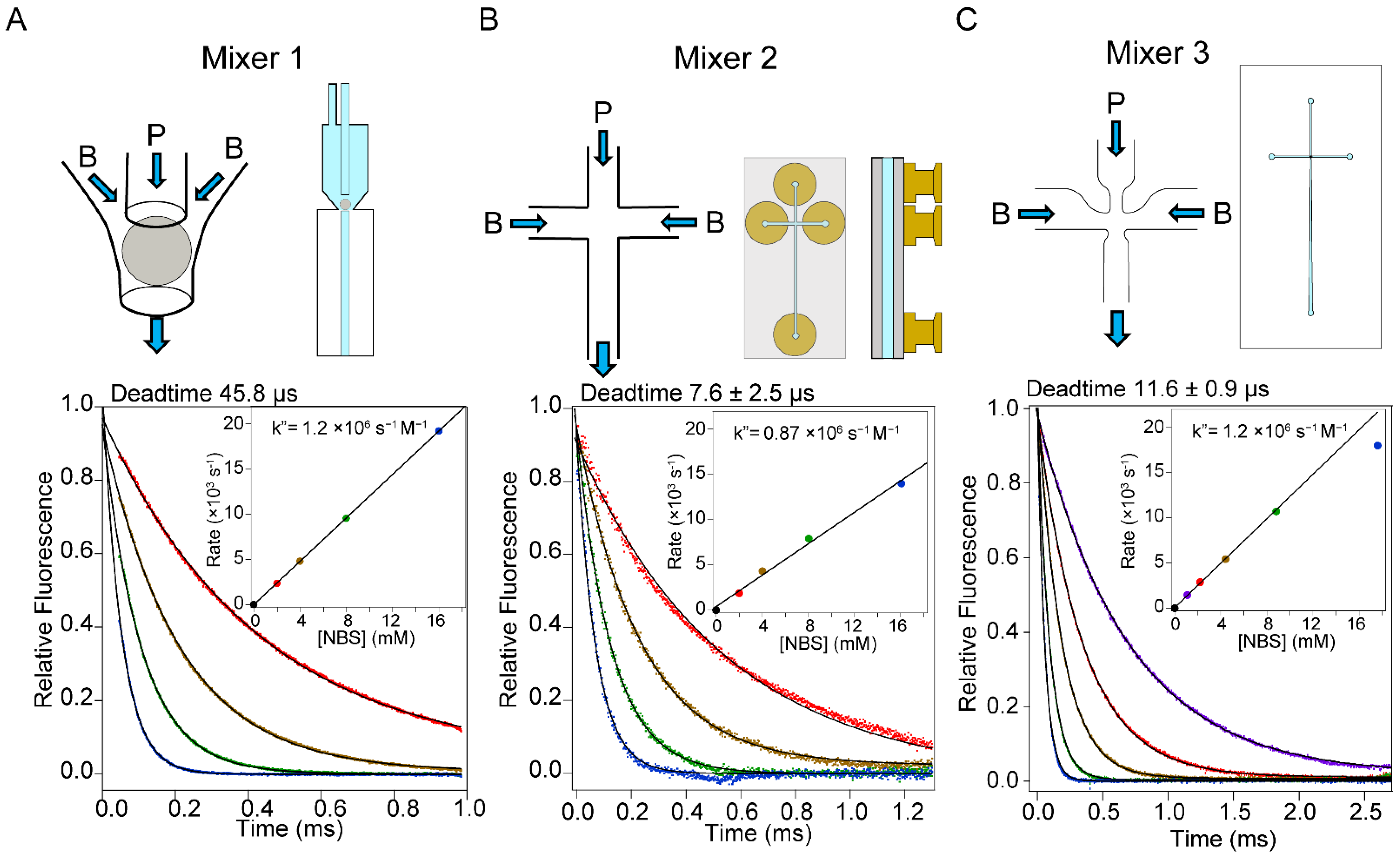
Figure 1. Summary of the mixer design and dead-time calibration of three continuous-flow mixing devices. Upper panels show schematics of the mixing regions and mixer/flow-cell assemblies for: (A) Mixer 1, the capillary mixer of Shastry et al. [8], (B) Mixer 2, a simple quartz cross-channel mixing chip (Translume, Inc., Ann Arbor, MI, USA) and (C) Mixer 3, a customized cross-channel mixing chip designed for reduced backpressure and expanded observation window (see Figure A1 in Appendix A for expanded diagram). The lower panels show representative examples of dead-time calibration using the pseudo-first-order NAT-NBS reaction. Typically, the fluorescent reagent (e.g., protein or NAT) is injected into central channel (P), and the second component (e.g., buffer, denaturant, ligand) is injected into the side channels B. The total flow rates in the experiments shown in A, B and C were 1 mL/s, 0.4 mL/s and 0.7 mL/s, respectively. The fluorescence decay curves are color-coded according to NBS concentration: purple for 1 mM, red for 2 mM, brown for 4 mM, green for 8 mM and blue for 16 m. Insets: determination of the second-order rate constant of the NAT-NBS reaction, based on the linear NBS concentration dependence of observed rate constants (determined by single-exponential non-linear least-squares fitting; solid lines).
Molecules 27 03392 g001
Figure 2. Optical configuration of our new continuous-flow instrument, using a UV laser in conjunction with a pair of Galvano mirrors to achieve uniform fluorescence excitation along the flow channel of the microfluidic mixing chip (Figure 1B,C).
Molecules 27 03392 g002
Figure 3. Calibration of the time axis of Mixer 3. (A) Schematic of the mixing region and conical flow channel (not to scale). The central inlet port (P in Figure 1) is on the left. The right exit is the observation channel. The x-axis is set along the observation channel with the origin on the entrance of it. x0 is the virtual vertex of the conical observation channel. The exit of the flow channel is located at x = L. The y-axis is set along the cross-section of the channel. The channel widths at the entrance (x = 0) and the exit (x = L) of the flow channel are w0 and wL, respectively. (B) Representative profiles of the NAT-NBS quenching reaction. The positions at x = 0.76 mm, 1.1 mm, 2.0 mm, 3.0 mm, 5.0 mm, 10 mm and 23 mm are shown by the lines in brown, red, orange-yellow, green-cyan and blue, respectively. (C) The concentration dependence of fluorescence intensity at representative positions. The data are fitted to Equation (4). (D) The profile of kt value obtained by curve fitting in panel C. (E) Dependence of distance x on kt.
Molecules 27 03392 g003
Figure 4. Optimization of mixing ratio and flow rate for Mixer 3. (A) Mixing ratio dependence and (B) flow rate dependence of dead time. (C) The NBS concentration dependence of rate constant obtained at several flow rates. The color code is shown in panel C.
Molecules 27 03392 g004
Figure 5. Mixing efficiency of Mixer 3 vs. flow rate assayed using potassium iodine quenching of tryptophan fluorescence. Residual fluorescence of NAT (10 mM) upon mixing with 1 mM potassium iodide in the absence (A) and presence (B) of 8 M urea. Color code: 0.4 mL/s (blue), 0.6 mL/s (green), 0.8 mL/s (orange) and 1.0 mL (red). The 95% mixing level is shown by the broken lines. The inlet panels show the time to achieve 95% mixing.
Molecules 27 03392 g005
Figure 6. Dead-time calibration performed in the presence of sucrose. NBS is dissolved in 17.9% sucrose, which matches the viscosity of 8.8 M urea (η/η0 = 1.777). The viscosity of sucrose after 1:10 mixing (16.2%, η/η0 = 1.663) matches that of 8 M urea.
Molecules 27 03392 g006
Figure 7. (A) Kinetics of refolding of acid-denatured cyt c (pH 2, salt-free) triggered by a jump to pH 4.5 (100 mM sodium acetate) recorded using Mixer 1 (green trace, 280 nm excitation) and Mixer 3 (red trace, 266 nm excitation). (B) Kinetics of refolding of cyt c (same conditions as in panel (A)) at different protein concentrations, as indicated.
Molecules 27 03392 g007
Figure 8. Binding kinetics of peptides from the C-terminus of CFTR to the first PDZ domain of NHERF1. (A) Kinetic traces of CFTR10 binding to PDZ1 of NHRF1. (B) Rate constants of the binding reaction for CFTR10 (blue) and CFTR6 (green). The line represents a hyperbolic fit of the rate constant vs. ligand concentration.
Molecules 27 03392 g008
Publisher’s Note: MDPI stays neutral with regard to jurisdictional claims in published maps and institutional affiliations.