Article

Comparison of the Characteristics of Recycled Carbon Fibers/Polymer Composites by Different Recycling Techniques

1
R&D Office 1st, Korea Carbon Industry Promotion Agency, Jeonju 54852, Korea
2
Department of Carbon-Nanomaterials Engineering, Jeonju University, Jeonju 55069, Korea
*
Author to whom correspondence should be addressed.
Molecules 2022, 27(17), 5663; https://doi.org/10.3390/molecules27175663
Submission received: 5 August 2022 / Revised: 29 August 2022 / Accepted: 30 August 2022 / Published: 2 September 2022

Abstract

:
In this study, three recycling methods, namely, mechanical grinding, steam pyrolysis, and the supercritical solvent process, which are used to acquire recycled carbon fibers (RCFs), were compared for their application in synthesizing polymer-matrix composites. RCF-reinforced polyethylene (PE) composites were prepared to compare the mechanical properties of the composites generated using the three recycling methods. The PE/RCF composites exhibited 1.5 times higher mechanical strength than the RCF-reinforced PE composites, probably because of the surface oxidation effects during the recycling processes that consequently enhanced interfacial forces between the RCF and the matrix. Further, the steam pyrolysis process showed the highest energy efficiency and can thus be applied on a large production scale in domestic recycled CF markets.

1. Introduction

Carbon-fiber-reinforced plastic (CFRP) is an advanced composite material having high strength, high elasticity, and extremely low weight. These properties have promoted its widespread application in various fields, such as automobiles, sports, aerospace, and the military [1,2,3,4,5,6]. However, the large-scale use of CFRPs generates vast quantities of waste. Generally, thermoplastic and thermosetting resins are the most commonly used matrixes in CFRPs. CFRPs with thermoplastic resins can be easily recycled because they are reversible. However, the separation of carbon fibers (CFs) from the matrix of thermosetting-based CFRPs is difficult, resulting in their disposal in landfills after incineration. This disposal type makes it difficult to recycle CFs; additionally, this process is costly and causes environmental pollution. Thus, the demand for waste recycling has been increasing [7,8,9].
Various recycling methods for waste CFRPs have been studied to reuse expensive CFs [10]. The main recycling methods are mechanical recycling [11,12], chemical processes [13,14], and thermal processing [15,16,17]. Among these, mechanical recycling is the simplest and the most cost-effective process; moreover, although CFs can be recovered from waste CFRP through grinding, crushing, and cutting, only pure CFs cannot be obtained [18]. The chemical process recycles CFs through decomposition using a solvent [19,20], a supercritical method [21,22], etc.; moreover, recycling through this process can be conducted while retaining the mechanical properties of CFs as much as possible. However, the continuous application of the chemical process for recycling CFs releases extensive amounts of harmful gases and generates toxic reagents, which is a major disadvantage [23]. Lastly, thermal processing, which is the most widely used recycling process for CFRPs, can recover relatively clean CFs by thermally decomposing organic molecules into smaller molecules. In addition, the mechanical properties of the CFs can be retained through this method (a tensile strength of 70–80% compared to virgin CF), thereby making it a suitable alternative for large-scale commercialization [23,24,25].
Recently, in European Union countries, upcycling, which is one step beyond the simple recycling process, has been used extensively in industrial applications. It is also attracting attention in several countries, such as the United States and Canada, as an eco-friendly production and ethical consumption method [26,27]. Because of its environmental and economic advantages, studies on the upcycling and recycling of CFRPs are increasing.
This study aimed to investigate mechanical recycling, supercritical recycling, and superheated steam recycling processes to compare the application characteristics of CF composites recycled by these methods. CFs recycled through each process were mixed with low-density polyethylene (LDPE) to form a composite to assess the mechanical, electrical, and thermal properties of the composites. Further, the application of surface treatment to CFs can result in the recovery of clean CFs and maintain their physical properties during recycling; additionally, the interfacial properties with the matrix can be improved. Therefore, upcycling waste CFRPs can further increase the resource value of the generated CFRP wastes.

2. Results and Discussion

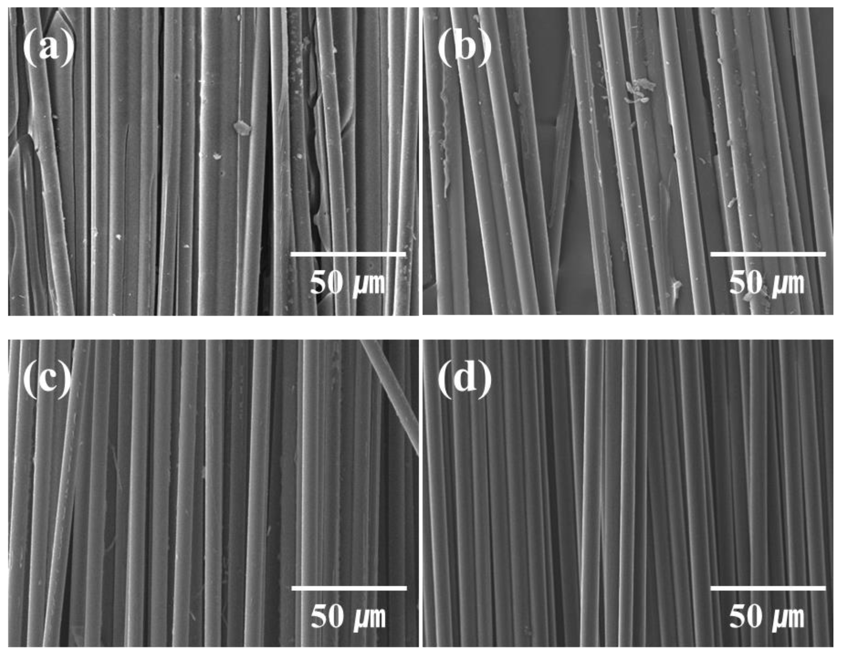
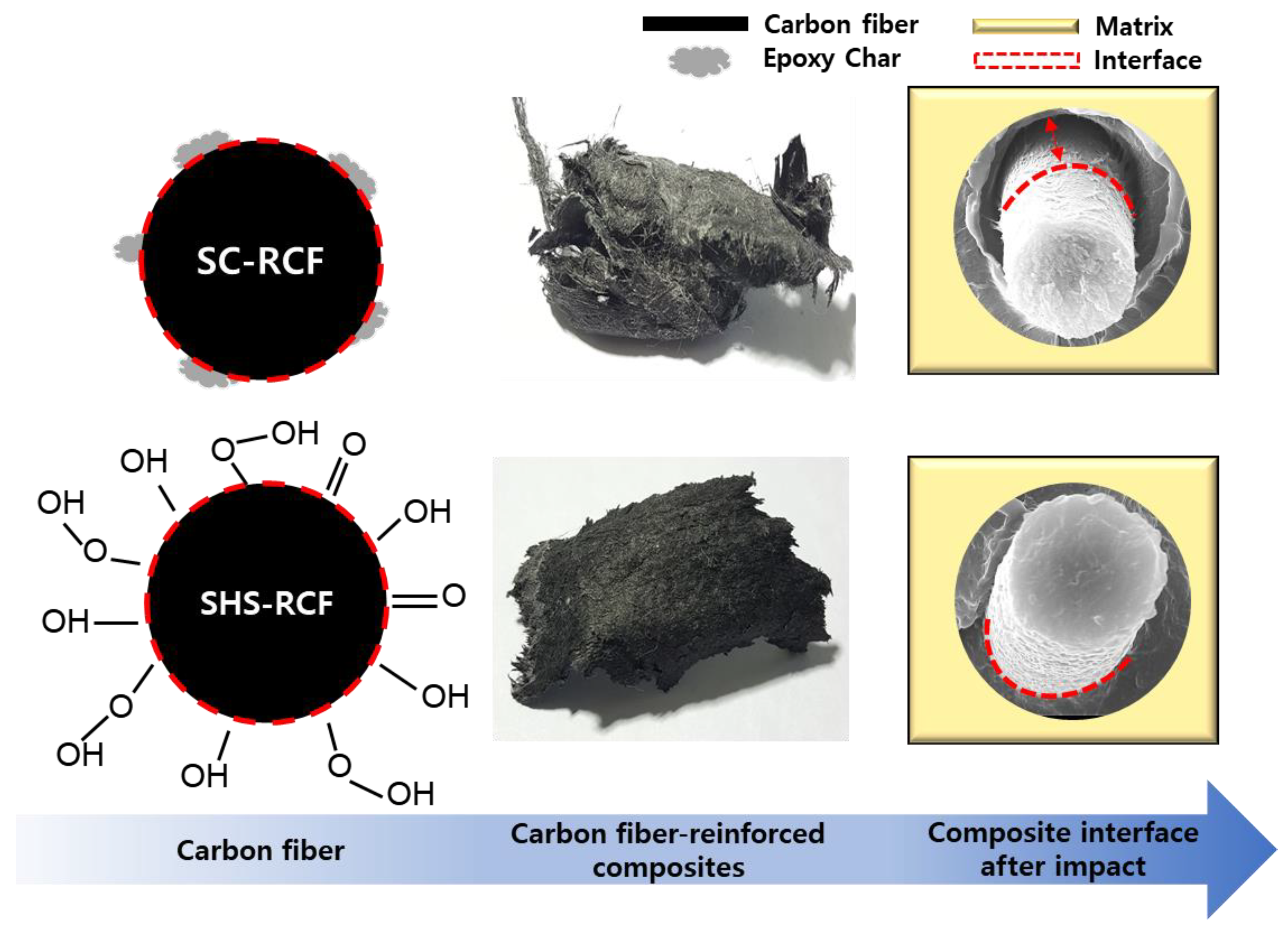
2.1. Characteristics of the CFRPs Acquired through the Studied Recycling Techniques

Figure 1 shows the SEM images of CFRP scrap waste, virgin CFs, supercritical recycled CFs, and superheated steam recycled CFs.
In the CFRP scrap waste, a large amount of resin was wrapped around the CF, and epoxy resin fragments broken during the cutting process were observed. Although some resin decomposition products remained on the recycled CF surface during the supercritical and superheated steam recycling methods, virgin CFs were recovered relatively effectively, as shown in the SEM image (Figure 1). Further, recycled CFs recovered from superheated steam showed relatively cleaner surfaces than those recovered by mechanical and supercritical recycling methods.

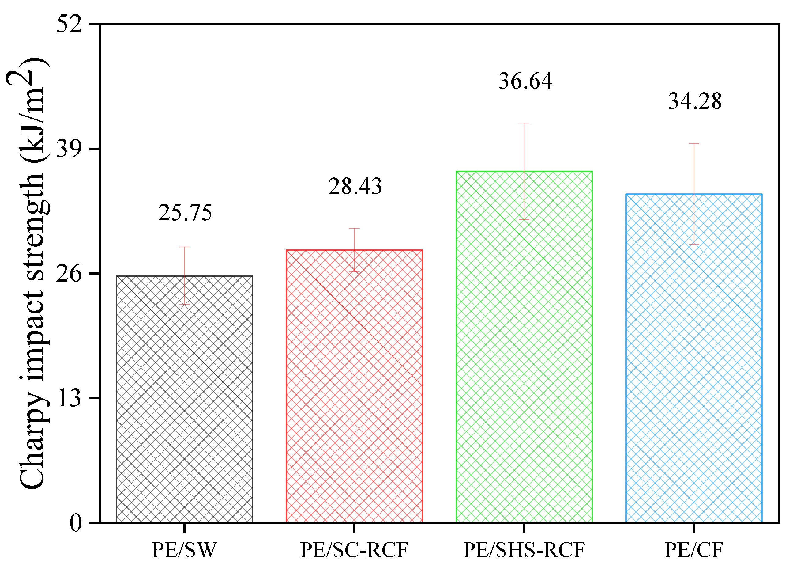
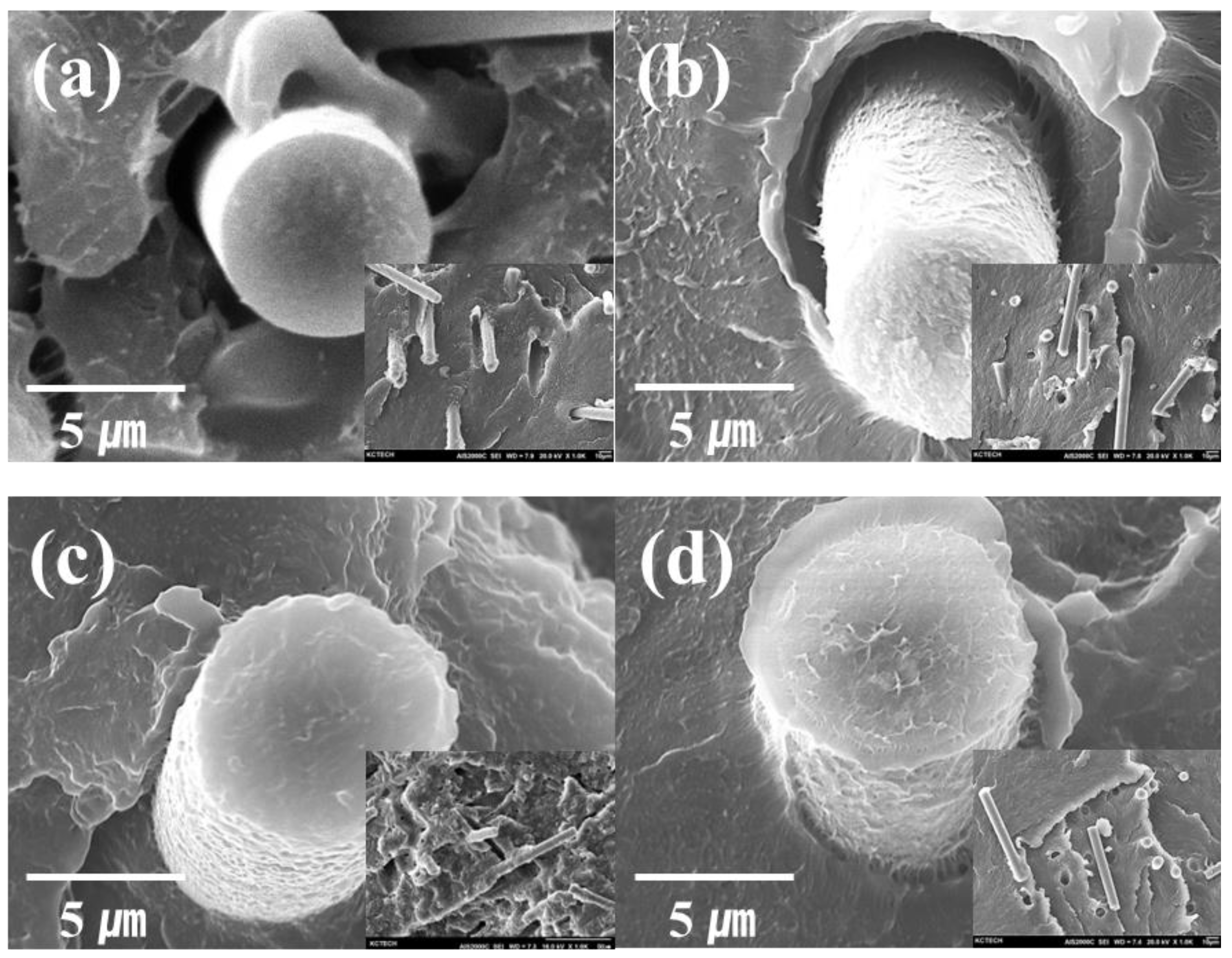
2.2. Physical Characteristics of the Various RCF-Reinforced Composites

The results of the Charpy pendulum impact test for the LDPE matrix CFRPs with different mixed fillers are presented in Figure 2.
The specific Charpy energy of the PE/SHS-RCF CFRPs was evidently higher than that of the PE/CF CFRPs. This could be attributed to the increase in the interfacial shear strength (IFSS), which improved the high-impact resistivity between the LDPE and CFs. Table 1 shows the results of previous studies [23] conducted on recycled CFs and untreated CFs under the same conditions as used in this study.
The average IFSS value for the CFs was 39.19 MPa. Further, the IFSS values of the RCFs were enhanced (47.06 MPa) after the surface pyrolysis of the CFRPs using SHS. Pyrolysis (SHS) oxidation introduces –OH, –CH–, H-bond, –C=O, and C–O functional groups successfully onto the fiber surface. The –OH or –COOH groups can form covalent interfacial bonds in the cross-linked polymer adhesive which couple to the fiber, effectively transferring stresses between the matrix and the fiber and improving interfacial adhesion. Furthermore, fracture toughness is improved by hydrogen and covalent bonding interactions. Surface functionalization increases polar components and the total surface free energy of the fibers. Moreover, the RCF surface treated with SHS contains hydrophilic functional groups, such as oxygen carboxyl, carbonyl, and hydroxyl. The high polar term in the total surface free energy can be expected to contribute to the good wettability and adhesion between the fiber and matrix. In the case of SC-RCF, reliable surface free energy values could not be obtained due to many impurities on the surface.
In this study, the specific Charpy energy reached 36.64 kJ/m2 for the PE/SHS-RCF, which meets the standard demands of engineered materials. This improved impact strength is believed to be due to the increased oxygen content after the surface pyrolysis of CFRPs with SHS.
As shown in Figure 3, the morphologies of the fractured surfaces of the four samples differ. Closer examination reveals that the fractured surface morphologies of (a) to (d) differ in roughness as well. The fractured surface of (c) differs from that of (a) and (b) because of the stronger adhesion between the CFs and the matrix in (d). As shown in (a), a smooth surface with marginally adhered resin can be seen on the CF surface in the debonded area; additionally, the matrix can be observed to have been detached from the fiber surface. This indicates cohesive failure at the interface between the matrix and CFs. Further, the absence of residual LDPE on the CF surface is direct evidence of a weak interface [28,29]. Figure 3d shows that the interface is closely connected to the resin due to having a higher bonding force than the samples (a) and (b). However, in the vicinity of the fiber, the resin shape was stretched by the impact. Consequently, sample (c), with no shape change at the interface between the fiber and the resin, showed the highest interfacial bonding force.

2.3. Thermal and Electrical Properties of RCF-Reinforced Composites

Table 2 enlists the horizontal thermal and electrical conductivity values of the CFRPs, which showed high impact strength.
The low thermal conductivity of LDPE (approximately 0.1 to 0.3 W/mK) can be enhanced by the filler effect (1 to 2 W/mK in the horizontal direction). The thermal conductivity of the PE/SHS-RCF sample in the horizontal direction was observed to be slightly higher than that of PE/CF, but it was judged to be an approximate value. This is because the CFs are well-dispersed during the molding and production of the composite material; additionally, the plurality of the fillers is oriented in the horizontal direction by the flow of the molten resin during hot compression. Because the effect of CFs on long fibers with high thermal conductivity is dominant, the degree of dispersion in CFs due to interfacial bonding force may result in the loss of internal heat transfer path, thereby subsequently affecting thermal conductivity (Figure 4).
Further, the results indicate that the high resistivity of LDPE (approximately 1015–1018 Ω·cm) can be lowered by the filling material (approximately 10−2 to 10−3 Ω·cm). In addition, the electrical conductivity slightly increased when CFs recycled from SHS were applied to CFRPs. These results indicate that SHS recycling enhances interfacial adhesion. Further, because the interfacial bonding strength of SHS-RCF was higher than that of virgin CFs, the electrical resistance of CFRPs applied with SHS-RCF decreased; that is, the interfacial bonding force at this stage can reduce the number of point defects and improve the electrical conductivity of CFRPs. Figure 4 is a schematic diagram showing the changes in interfacial adhesion that can occur as recycling methods of the CFs. As a result, it was confirmed that the interfacial adhesion strength was statistically increased due to the cleanliness (degree of recovery) and oxidation of the carbon fiber surface, and the most important factor was the recycling technology that can recover cleanly.

3. Materials and Methods

3.1. Materials

In this study, the CFs with 4.9 GPa and 230 GPa of tensile strength and modulus, respectively, were supplied by Toray (12 K, T700). The average diameter and density of the CFs were 7 µm and 1.8 g/cm3, respectively. The epoxy resin, diglycidyl ether of bisphenol-A (DGEBA, YD-128, Kukdo Chem., Seoul, Korea), with an equivalent weight of 185–190 g/eq and a viscosity value of 11500–13500 cps at 25 °C, was used as a matrix. Diaminodiphenylmethane (DDM, Tokyo Chem., Tokyo, Japan) was selected as a hardener, and methylethylketone (MEK, Daejung Chem., Shiheung, Korea) was used to reduce the high viscosity of DGEBA.
LDPE (XJ800), with 0.914 cm3/g density and 103 °C melting temperature, was purchased from Lotte Chemical Corporation (Seoul, Korea).

3.2. Sample Preparation

CFs were impregnated with thermosetting resin by the drum winding method and converted into prepregs after removing the solvent for 48 h. CFRPs prepared using the hot press method at 175 °C had 36% resin content.
Supercritical recycling involved heating a mixture of CFRPs and ethanol (1:5 weight ratio) in a sealed reactor vessel above 250 °C for 30 min. Supercritical recycling samples were fabricated at a pressure of 80 bar. The resultant samples were then rapidly washed, and the remaining product was washed with deionized water at least thrice. Subsequently, the recycled CFs were vacuum-filtered and dried in a heating oven at 100 °C for 3 h.
A fixed SiC furnace was used to pyrolyze the CFRP composites. An alumina tube with 1000 mm length and 80 mm inner diameter was horizontally mounted in an electrical resistance furnace (15 kW) and heated to a final temperature of 550 °C. A detachable porcelain crucible containing the sample was placed at the center of the quartz tube. The CFRPs were heated to 550 °C at 10 °C/min in the SiC furnace under H2O (liquid flow 2 mL/min) and maintained at the target temperature for 30 min to obtain carbonized CFRPs. Subsequently, the gas flow was switched to air (O2-21% under N2) at a rate of 200 mL/min, while the temperature was increased to and maintained at 550 °C for 60 min. Subsequently, recycled carbon fibers (RCFs) were obtained after cooling to room temperature.
To produce a composite with a thermoplastic resin, the fillers were cut into a unit size of 1 inch. Composites were prepared by mixing LDPE and CF at a tailored mixing ratio; subsequently, the mixture was melt-blended in a mixing chamber at 130 °C with a screw speed of 70 rpm for 30 min in an internal mixer. The total weight ratio of the matrix to the filler was fixed at 5:1. After melt-blending, each sample was molded by hot pressing using a vacuum bag molding method. The processing temperature, time, and pressure were maintained at 130 °C, 15 min, and 10 MPa, respectively. Table 3 enlists the formulation of various mixing fillers of the CFRPs in the composites.

3.3. Characterization of Samples

The morphologies of PE/RCF and PE/CF were investigated using a scanning electron microscope (SEM, AIS2000C, Seron Tech. Inc., Uiwang-si, Korea). To reduce charging during SEM imaging, samples were initially placed on a sample holder and coated with platinum. The base pressure of the analyzer chamber was approximately 5 × 10⁻⁵ Pa and the acceleration voltage was set to 15 kV.
The thermal conductivity of the composite sample was measured by the transient plane source (TPS) method using a hot disk instrument (TPS2500S, Hot Disk Inc., Gothenburg, Sweden), and the conductivity was measured in the horizontal direction.
A nickel coil wrapped in a polyimide film (Kapton) with a diameter of 6.4 mm (#5501) was used as a probe for measuring the thermal conductivity and thermal diffusivity of the composite sample and to reduce the error caused by the anisotropic fillers. The estimated data reproducibility and accuracy of the equipment provided by the manufacturer were more than 1% and 5%, respectively. In all experiments, the measuring instrument was preheated for 30 min or more to ensure analysis reliability, and the measurement environment was maintained at 25 °C and 30% relative humidity.
All specimens were pressed flat using an automatic polishing device at intervals of 5 min using sandpapers of 1000, 2000, and 4000 grades. The samples were placed approximately 6 cm from the center of the automatic polishing machine, and a force of 50 N and a speed of 150 rpm were applied uniformly across the samples. Finally, the finished samples were uniformly cut into dimensions of 30 × 30 × 3 mm.
The electrical resistivity of the samples was measured using a Loresta GP resistivity meter (MCP-T610, Mitusbishi Chemical Co., Tokyo, Japan) connected to a 4-point-probe (MCP-TP03P, Mitsubishi Chemical Co., Tokyo, Japan), which was used to eliminate the effect of contact resistance. Further, at least 10 samples were tested for the reliability of each formulation.

3.4. Measurement of Physical Properties

An impact strength test was conducted to observe the changes in the mechanical strength of the composites having the fillers. A Charpy (CEAST® Resil Impactor, CEAST, MA, FL, USA) pendulum impact test was employed according to ASTM D6110 [30] to examine the total required energy until the final fracture of the composite material.

4. Conclusions

This study compared the characteristics of CFs/polymer composites acquired through different recycling methods. The results indicated that pyrolysis and supercritical recycling methods were efficient. The recycled fiber “PE/SHS-RCF” exhibited an impact strength of 106.88% compared with the commonly used fiber (T700). Further, the thermal conductivity of the CFs was as high as 106%. Moreover, the formation of oxygen functional groups on the CF surface during pyrolysis increased the IFSS between the resins. Lastly, the supercritical H2O/CO2 process showed the highest energy efficiency and, thus, the further modernization and development of this process on a large production scale can facilitate its application in domestic recycled CF markets.

Author Contributions

Conceptualization, K.-W.K. and B.-J.K.; Data curation, K.-W.K.; Writing—review & editing, Formal analysis, D.-K.K. and K.-W.K.; Methodology, B.-J.K.; Project administration, Funding acquisition, W.H.; Writing original draft, D.-K.K. All authors have read and agreed to the published version of the manuscript.

Funding

This study was supported by the “Material Parts Technology Development Project (Project No. 20012817),” which was funded by the Ministry of Trade, Industry, and Energy (MOTIE), Republic of Korea.

Institutional Review Board Statement

Not applicable.

Informed Consent Statement

Not applicable.

Data Availability Statement

Not applicable.

Conflicts of Interest

The authors declare that they have no known competing financial interests or personal relationships that could have appeared to influence the work reported in this paper.

Sample Availability

Not available.

References

  1. Yang, J.; Liu, J.; Liu, W.; Wang, J.; Tang, T. Recycling of carbon fibre reinforced epoxy resin composites under various oxygen concentrations in nitrogen–oxygen atmosphere. J. Anal. Appl. Pyrolysis 2015, 112, 253–261. [Google Scholar] [CrossRef]
  2. Xu, Y.; Dai, S.; Bi, L.; Jiang, J.; Zhang, H.; Chen, Y. Catalyst-free self-healing bio-based vitrimer for a recyclable, reprocessable, and self-adhered carbon fiber reinforced composite. Chem. Eng. J. 2022, 429, 132518. [Google Scholar] [CrossRef]
  3. Pei, C.; Chen, P.Y.; Kong, S.C.; Wu, J.; Zhu, J.H.; Xing, F. Recyclable separation and recovery of carbon fibers from CFRP composites: Optimization and mechanism. Sep. Purif. Technol. 2021, 278, 119591. [Google Scholar] [CrossRef]
  4. Jeong, J.S.; Kim, K.W.; Chung, D.C.; An, K.H.; Kim, B.J. A study on the correlation between microstructure change and the mechanical strength of a single CF modified by electron beam. Carbon Lett. 2022, 32, 567–579. [Google Scholar] [CrossRef]
  5. Lee, D.K.; Kim, Y.E.; Kwon, O.H.; Park, W.H.; Cho, D.H. Carbon fiber coating with MWCNT in the presence of polyethyleneimine of different molecular weights and the effect on the interfacial shear strength of thermoplastic and thermosetting carbon fiber composites. Carbon Lett. 2021, 31, 407–417. [Google Scholar] [CrossRef]
  6. Wang, X.; Qian, X.; Zhang, Y.; Wang, X.; Song, S.; Zhang, C. Surface oxidation of PAN-based ultrahigh modulus carbon fibers (UHMCFs) and its effect on the properties of UHMCF/EP composites. Carbon Lett. 2021, 31, 449–461. [Google Scholar] [CrossRef]
  7. Xing, M.; Li, Z.; Zheng, G.; Du, Y.; Chen, C.; Wang, Y. Recycling of carbon fiber-reinforced epoxy resin composite via a novel acetic acid swelling technology. Compos. Part B Eng. 2021, 224, 109230. [Google Scholar] [CrossRef]
  8. Palmay, P.; Haro, C.; Huacho, I.; Barzallo, D.; Bruno, J.C. Production and Analysis of the Physicochemical Properties of the Pyrolytic Oil Obtained from Pyrolysis of Different Thermoplastics and Plastic Mixtures. Molecules 2022, 27, 3287. [Google Scholar] [CrossRef]
  9. Park, J.M.; Kwon, D.J.; Wang, Z.J.; Gu, G.Y.; DeVries, K.L. Effect of thermal treatment temperatures on the reinforcing and interfacial properties of recycled carbon fiber–phenolic composites. Compos. Part A Appl. Sci. Manuf. 2013, 47, 156–164. [Google Scholar] [CrossRef]
  10. Liu, Y.; Liu, J.; Jiang, Z.; Tang, T. Chemical recycling of carbon fibre reinforced epoxy resin composites in subcritical water: Synergistic effect of phenol and KOH on the decomposition efficiency. Polym. Degrad. Stab. 2012, 97, 214–220. [Google Scholar] [CrossRef]
  11. Feraboli, P.; Kawakami, H.; Wade, B.; Gasco, F.; DeOto, L.; Masini, A. Recyclability and reutilization of carbon fiber fabric/epoxy composites. J. Compos. Mater. 2011, 46, 1459–1473. [Google Scholar] [CrossRef]
  12. Palmer, J.; Ghita, O.R.; Savage, L.; Evans, K.E. Successful closed-loop recycling of thermoset composites. Compos. Part A Appl. Sci. Manuf. 2009, 40, 490–498. [Google Scholar] [CrossRef]
  13. Kim, D.H.; Lee, M.; Goh, M. Enhanced and Eco-Friendly Recycling of Carbon-Fiber-Reinforced Plastics Using Water at Ambient Pressure. ACS Sustain. Chem. Eng. 2019, 8, 2433–2440. [Google Scholar] [CrossRef]
  14. Lee, M.; Kim, D.H.; Park, J.J.; You, N.H.; Goh, M. Fast chemical recycling of carbon fiber reinforced plastic at ambient pressure using an aqueous solvent accelerated by a surfactant. Waste Manag. 2021, in press. [Google Scholar] [CrossRef]
  15. Mustata, F.; Tudorachi, N.; Bicu, I. The kinetic study and thermal characterization of epoxy resins crosslinked with amino carboxylic acids. J. Anal. Appl. Pyrolysis 2015, 112, 180–191. [Google Scholar] [CrossRef]
  16. Mazzocchetti, L.; Benelli, T.; D’Angelo, E.; Leonardi, C.; Zattini, G.; Giorgini, L. Validation of carbon fibers recycling by pyro-gasification: The influence of oxidation conditions to obtain clean fibers and promote fiber/matrix adhesion in epoxy composites. Compos. Part A Appl. Sci. Manuf. 2018, 112, 504–514. [Google Scholar] [CrossRef]
  17. Nahil, M.A.; Williams, P.T. Recycling of carbon fibre reinforced polymeric waste for the production of activated carbon fibres. J. Anal. Appl. Pyrolysis 2011, 91, 67–75. [Google Scholar] [CrossRef]
  18. Obunai, K.; Fukuta, T.; Ozaki, K. Carbon fiber extraction from waste CFRP by microwave irradiation. Compos. Part A Appl. Sci. Manuf. 2015, 78, 160–165. [Google Scholar] [CrossRef]
  19. Braun, D.; Von Gentzkow, W.; Rudolf, A.P. Hydrogenolytic degradation of thermosets. Polym. Degrad. Stab. 2011, 74, 25–32. [Google Scholar] [CrossRef]
  20. Dang, W.; Kubouchi, M.; Sembokuya, H.; Tsuda, K. Chemical recycling of glass fiber reinforced epoxy resin cured with amine using nitric acid. Polymer 2005, 46, 1905–1912. [Google Scholar] [CrossRef]
  21. Gong, X.; Kang, H.; Liu, Y.; Wu, S. Decomposition mechanisms and kinetics of amine/anhydride-cured DGEBA epoxy resin in near-critical water. RSC Adv. 2015, 5, 40269–40282. [Google Scholar] [CrossRef]
  22. Prinçaud, M.; Aymonier, C.; Loppinet-Serani, A.; Perry, N.; Sonnemann, G. Environmental Feasibility of the Recycling of Carbon Fibers from CFRPs by Solvolysis Using Supercritical Water. ACS Sustain. Chem. Eng. 2014, 2, 1498–1502. [Google Scholar] [CrossRef]
  23. Kim, K.W.; Lee, H.M.; An, J.H.; Chung, D.C.; An, K.H.; Kim, B.J. Recycling and characterization of carbon fibers from carbon fiber reinforced epoxy matrix composites by a novel super-heated-steam method. J. Environ. Manag. 2017, 203, 872–879. [Google Scholar] [CrossRef] [PubMed]
  24. Kim, K.W.; Jeong, J.S.; An, K.H.; Kim, B.J. A Low Energy Recycling Technique of Carbon Fibers-Reinforced Epoxy Matrix Composites. Ind. Eng. Chem. Res. 2019, 58, 618–624. [Google Scholar] [CrossRef]
  25. Jeong, J.S.; Kim, K.W.; An, K.H.; Kim, B.J. Fast recovery process of carbon fibers from waste carbon fibers-reinforced thermoset plastics. J. Environ. Manag. 2019, 247, 816–821. [Google Scholar] [CrossRef]
  26. Niakantan, G.; Nutt, S. Reuse and upcycling of thermoset prepreg scrap: Case study with out-of-autoclave carbon fiber/epoxy prepreg. J. Compos. Mater. 2017, 52, 341–360. [Google Scholar] [CrossRef]
  27. Stanescu, M.D. State of the art of post-consumer textile waste upcycling to reach the zero waste milestone. Environ. Sci. Pollut. Res. 2021, 28, 14253–14270. [Google Scholar] [CrossRef]
  28. Kim, K.W.; Jeong, J.S.; An, K.H.; Kim, B.J. A study on the microstructural changes and mechanical behaviors of carbon fibers induced by optimized electrochemical etching. Compos. Part B Eng. 2019, 165, 764–771. [Google Scholar] [CrossRef]
  29. Kim, K.W.; Kim, D.K.; Kim, B.S.; An, K.H.; Park, S.J.; Rhee, K.Y.; Kim, B.J. Cure behaviors and mechanical properties of carbon fiber-reinforced nylon6/epoxy blended matrix composites. Compos. Part B Eng. 2017, 112, 15–21. [Google Scholar] [CrossRef]
  30. ASTM Standard D6110; Standard Test Method for Determining the Charpy Impact Resistance of Notched Specimens of Plastic. ASTM International: West Conshohocken, PA, USA, 2017. [CrossRef]
Figure 1. SEM images of waste and recycled carbon fiber (CF) acquired through different recycling methods. (a) CFRP scrap wastes, (b) recycled CFs from supercritical method, (c) recycled CFs from superheated steam pyrolysis, and (d) virgin CFs.
Molecules 27 05663 g001
Figure 2. Charpy test results of the impact strength of RCF-reinforced low-density polyethylene (LDPE).
Molecules 27 05663 g002
Figure 3. SEM images of the fractured surfaces of polymer composites with CF types acquired from the Charpy pendulum impact test. (a) PE/SW, (b) PE/SC-RCF, (c) PE/SHS-RCF, and (d) PE/CF.
Molecules 27 05663 g003
Figure 4. A schematic of interfacial adhesion changes of carbon fibers by recycling methods.
Molecules 27 05663 g004
Table 1. Summary of the results of previous studies according to carbon fiber type (B. J. Kim et al.) [23].
PropertyUnitsSample Name
SC-RCF* SHS-RCF* CF(T700)
Tensile strengthGPa3.423.884.28
Interfacial shear strengthMPa33.6247.0639.19
Oxygen content%13.3714.298.79
Polarity valuemN/m-12.525.66
Surface free energymN/m-35.3527.77
* B. J. Kim et al., Journal of Environmental Management, 203, 872–879 2017 [23].
Table 2. Thermal and electrical conductivity of polymer composites with different carbon fiber types.
PropertyUnitsSample Name
PE/SHS-RCFPE/CF
Heat conductivityW/mK1.871.76
ResistivityΩ·cm3.2 × 10−31.5 × 10⁻²
Table 3. CFRP formulation for composite preparation.
Sample NameFiller TypeLDPE (g)Filler (g)Temperature (°C)Mix (rpm)Time (min)
PE/SWCFRP scrap wastes150301307030
PE/SC-RCFRecycled CFs(supercritical)
PE/SHS-RCFRecycled CFs (superheated steam)
PE/CFT-700 CFs
Publisher’s Note: MDPI stays neutral with regard to jurisdictional claims in published maps and institutional affiliations.

