
Designing Hollow Carbon Sphere with Hierarchal Porous for Na-S Systems with Ultra-Long Cycling Stabilities
Abstract
:1. Introduction
2. Results
3. Materials and Methods
3.1. Materials
3.2. Material Characterizations
3.3. Electrochemical Measurements
4. Conclusions
Author Contributions
Funding
Institutional Review Board Statement
Informed Consent Statement
Data Availability Statement
Conflicts of Interest
References
- Li, S.; Han, Y. Recent Advances of Catalytic Effects in Cathode Materials for Room-Temperature Sodium-Sulfur Batteries. Chempluschem 2021, 86, 1461–1471. [Google Scholar] [CrossRef]
- Wang, Y.; Zhou, D. Revitalising sodium-sulfur batteries for non-high-temperature operation: A crucial review. Energy Environ. Sci. 2020, 13, 3848–3879. [Google Scholar] [CrossRef]
- Syali, M.S.; Kumar, D. Recent advances in electrolytes for room-temperature sodium-sulfur batteries: A review. Energy Storage Mater. 2020, 31, 352–372. [Google Scholar] [CrossRef]
- Wang, L.; Wang, T. The promises, challenges and pathways to room-temperature sodium-sulfur batteries. Natl. Sci. Rev. 2022, 9, nwab050. [Google Scholar] [CrossRef]
- Li, C.; Wang, Z.-B. Recent advances in cathode materials for Li-S battery: Structure and performance. Rare Met. 2017, 36, 365–380. [Google Scholar] [CrossRef]
- Zeng, L.-C.; Li, W.-H. Recent progress in Li-S and Li-Se batteries. Rare Met. 2017, 36, 339–364. [Google Scholar] [CrossRef]
- Zhao, W.-M.; Shen, J.-D. Functional catalysts for polysulfide conversion in Li-S batteries: From micro/nanoscale to single atom. Rare Met. 2022, 41, 1080–1100. [Google Scholar] [CrossRef]
- Wang, Y.; Huang, X.L. Nanostructure Engineering Strategies of Cathode Materials for Room-Temperature Na-S Batteries. ACS Nano 2022, 16, 5103–5130. [Google Scholar] [CrossRef] [PubMed]
- Wang, Y.-X.; Zhang, B. Room-Temperature Sodium-Sulfur Batteries: A Comprehensive Review on Research Progress and Cell Chemistry. Adv. Energy Mater. 2017, 7, e12520. [Google Scholar] [CrossRef]
- Carter, R.; Oakes, L. A Sugar-Derived Room-Temperature Sodium Sulfur Battery with Long Term Cycling Stability. Nano Lett. 2017, 17, 1863–1869. [Google Scholar] [CrossRef]
- Hu, L.; Lu, Y. Ultramicroporous Carbon through an Activation-Free Approach for Li-S and Na-S Batteries in Carbonate-Based Electrolyte. ACS Appl. Mater. Interfaces 2017, 9, 13813–13818. [Google Scholar] [CrossRef] [PubMed]
- Zhang, L.; Zhang, B. Self-Assembling Hollow Carbon Nanobeads into Double-Shell Microspheres as a Hierarchical Sulfur Host for Sustainable Room-Temperature Sodium-Sulfur Batteries. ACS Appl. Mater. Interfaces 2018, 10, 20422–20428. [Google Scholar] [CrossRef] [PubMed]
- Guo, Q.; Li, S. Ultrastable Sodium-Sulfur Batteries without Polysulfides Formation Using Slit Ultramicropore Carbon Carrier. Adv. Sci. 2020, 7, 1903246. [Google Scholar] [CrossRef]
- Bo, M.; Wang, Y. Coordination-resolved local bond relaxation and electron binding-energy shift of Pb solid skins and atomic clusters. J. Mater. Chem. C 2014, 2, 6090–6096. [Google Scholar] [CrossRef]
- Ji, X.; Evers, S. Stabilizing lithium-sulphur cathodes using polysulphide reservoirs. Nat. Commun. 2011, 2, 325. [Google Scholar] [CrossRef]
- Li, Z.; Jiang, Y. A Highly Ordered Meso@Microporous Carbon-Supported Sulfur@Smaller Sulfur Core-Shell Structured Cathode for Li-S Batteries. ACS Nano 2014, 8, 9295–9303. [Google Scholar] [CrossRef] [PubMed]
- Xin, S.; Gu, L. Smaller sulfur molecules promise better lithium-sulfur batteries. J. Am. Chem. Soc. 2012, 134, 18510–18513. [Google Scholar] [CrossRef] [PubMed]
- Schuster, J.; He, G. Spherical ordered mesoporous carbon nanoparticles with high porosity for lithium-sulfur batteries. Angew. Chem. 2012, 51, 3591–3595. [Google Scholar] [CrossRef]
- Li, Z.; Yuan, L. Insight into the Electrode Mechanism in Lithium-Sulfur Batteries with Ordered Microporous Carbon Confined Sulfur as the Cathode. Adv. Energy Mater. 2014, 4, 1301473. [Google Scholar] [CrossRef]
- Zhang, P.; Ma, Z. Mechanical properties of Li–Sn alloys for Li-ion battery anodes: A first-principles perspective. AIP Adv. 2016, 6, 015107. [Google Scholar] [CrossRef] [Green Version]
- Lu, Q.; Xu, Y.-y. The effect of nitrogen and/or boron doping on the electrochemical performance of non-caking coal-derived activated carbons for use as supercapacitor electrodes. New Carbon Mater. 2017, 32, 442–450. [Google Scholar] [CrossRef]
- Ma, Z.; Xie, Z. Softening by electrochemical reaction-induced dislocations in lithium-ion batteries. Scr. Mater. 2017, 127, 33–36. [Google Scholar] [CrossRef]
- Xu, G.-R.; Min, X.-P. Sonochemical synthesis of a Mn3O4/MnOOH nanocomposite for electrochemical energy storage. J. Alloys Compd. 2017, 691, 1018–1023. [Google Scholar] [CrossRef]
- Wei, S.; Xu, S. A stable room-temperature sodium-sulfur battery. Nat. Commun. 2016, 7, 11722. [Google Scholar] [CrossRef] [PubMed]
- Ge, P.; Li, S. Hierarchical Hollow-Microsphere Metal-Selenide@Carbon Composites with Rational Surface Engineering for Advanced Sodium Storage. Adv. Energy Mater. 2019, 9, 1803035. [Google Scholar] [CrossRef]
- Ge, P.; Hou, H. Multidimensional Evolution of Carbon Structures Underpinned by Temperature-Induced Intermediate of Chloride for Sodium-Ion Batteries. Adv. Sci. 2018, 5, 1800080. [Google Scholar] [CrossRef]
- Cheng, J.J.; Liu, L.F. Sulfur/CuxS hybrid material for Li/S primary battery with improved discharge capacity. Mater. Chem. Phys. 2019, 224, 384–388. [Google Scholar] [CrossRef]
- Cheng, J.J.; Ou, Y. Nickel sulfide cathode for stable charge-discharge rates in lithium rechargeable battery. Mater. Chem. Phys. 2019, 231, 131–137. [Google Scholar] [CrossRef]
- Peng, H.-J.; Huang, J.-Q. Nanoarchitectured Graphene/CNT@Porous Carbon with Extraordinary Electrical Conductivity and Interconnected Micro/Mesopores for Lithium-Sulfur Batteries. Adv. Funct. Mater. 2014, 24, 2772–2781. [Google Scholar] [CrossRef]
- Yang, Y.; Huang, X. Mn3O4 with different morphologies tuned through one-step electrochemical method for high-performance lithium-ion batteries anode. J. Alloys Compd. 2019, 771, 335–342. [Google Scholar] [CrossRef]
- Cook, J.B.; Kim, H.-S. Mesoporous MoS2 as a Transition Metal Dichalcogenide Exhibiting Pseudocapacitive Li and Na-Ion Charge Storage. Adv. Energy Mater. 2016, 6, 1501937. [Google Scholar] [CrossRef]
- Mei, B.-A.; Lau, J. Physical Interpretations of Electrochemical Impedance Spectroscopy of Redox Active Electrodes for Electrical Energy Storage. J. Phys. Chem. C 2018, 122, 24499–24511. [Google Scholar] [CrossRef]
- Brezesinski, T.; Wang, J. Ordered mesoporous alpha-MoO3 with iso-oriented nanocrystalline walls for thin-film pseudocapacitors. Nat. Mater. 2010, 9, 146–151. [Google Scholar] [CrossRef]
- Salanne, M.; Rotenberg, B. Efficient storage mechanisms for building better supercapacitors. Nat. Energy 2016, 1, 16070. [Google Scholar] [CrossRef]
- Choi, C.; Ashby, D.S. Achieving high energy density and high power density with pseudocapacitive materials. Nat. Rev. Mater. 2019, 5, 5–19. [Google Scholar] [CrossRef]
- Bao, W.; Wang, R. Porous Heteroatom-Doped Ti3C2Tx MXene Microspheres Enable Strong Adsorption of Sodium Polysulfides for Long-Life Room-Temperature Sodium-Sulfur Batteries. ACS Nano 2021, 15, 16207–16217. [Google Scholar] [CrossRef]
- Guo, Q.; Sun, S. A novel one-step reaction sodium-sulfur battery with high areal sulfur loading on hierarchical porous carbon fiber. Carbon Energy 2021, 3, 440–448. [Google Scholar] [CrossRef]
- Kim, H.; Sadan, M.K. Enhanced reversible capacity of sulfurized polyacrylonitrile cathode for room-temperature Na/S batteries by electrochemical activation. Chem. Eng. J. 2021, 426, 130787. [Google Scholar] [CrossRef]
- Liu, Y.; Li, X. Macro-microporous carbon with a three-dimensional channel skeleton derived from waste sunflower seed shells for sustainable room-temperature sodium sulfur batteries. J. Alloys Compd. 2021, 853, 157316. [Google Scholar] [CrossRef]
- Luo, S.; Ruan, J. Flower-Like Interlayer-Expanded MoS2-x Nanosheets Confined in Hollow Carbon Spheres with High-Efficiency Electrocatalysis Sites for Advanced Sodium-Sulfur Battery. Small 2021, 17, 2101879. [Google Scholar] [CrossRef]
- Ma, F.; Hu, P. Yolk@Shell Structured MnS@Nitrogen-Doped Carbon as a Sulfur Host and Polysulfide Conversion Booster for Lithium/Sodium Sulfur Batteries. ACS Appl. Energy Mater. 2021, 4, 3487–3494. [Google Scholar] [CrossRef]
- Ma, Q.; Zhong, W. Multi-step Controllable Catalysis Method for the Defense of Sodium Polysulfide Dissolution in Room-Temperature Na-S Batteries. ACS Appl. Mater. Interfaces 2021, 13, 11852–11860. [Google Scholar] [CrossRef]
- Wang, L.; Wang, H. Manipulating the Electronic Structure of Nickel via Alloying with Iron: Toward High-Kinetics Sulfur Cathode for Na-S Batteries. ACS Nano 2021, 15, 15218–15228. [Google Scholar] [CrossRef]
- Wang, Y.; Lai, Y. Tunable Electrocatalytic Behavior of Sodiated MoS2 Active Sites toward Efficient Sulfur Redox Reactions in Room-Temperature Na-S Batteries. Adv. Mater. 2021, 33, 2100229. [Google Scholar] [CrossRef] [PubMed]
- Xiao, F.; Wang, H. MOF-Derived CoS2/N-Doped Carbon Composite to Induce Short-Chain Sulfur Molecule Generation for Enhanced Sodium-Sulfur Battery Performance. ACS Appl. Mater. Interfaces 2021, 13, 18010–18020. [Google Scholar] [CrossRef] [PubMed]
- Yang, H.; Zhou, S. Architecting Freestanding Sulfur Cathodes for Superior Room-Temperature Na-S Batteries. Adv. Funct. Mater. 2021, 31, 2102280. [Google Scholar] [CrossRef]
- Ye, X.; Ruan, J. Enabling a Stable Room-Temperature Sodium-Sulfur Battery Cathode by Building Heterostructures in Multichannel Carbon Fibers. ACS Nano 2021, 15, 5639–5648. [Google Scholar] [CrossRef]
- Aslam, M.K.; Hussain, T. Sulfur encapsulation into yolk-shell Fe2N@nitrogen doped carbon for ambient-temperature sodium-sulfur battery cathode. Chem. Eng. J. 2022, 429, 132389. [Google Scholar] [CrossRef]
- Liu, H.; Wu, Y. Anthozoan-like porous nanocages with nano-cobalt-armed CNT multifunctional layers as a cathode material for highly stable Na-S batteries. Inorg. Chem. Front. 2022, 9, 645–651. [Google Scholar] [CrossRef]
- Wang, C.; Cui, J. Regulating the Deposition of Insoluble Sulfur Species for Room Temperature Sodium-Sulfur Batteries. Chem. Res. Chin. Univ. 2022, 38, 128–135. [Google Scholar] [CrossRef]
- Wu, C.; Lei, Y. Continuous Carbon Channels Enable Full Na-Ion Accessibility for Superior Room-Temperature Na-S Batteries. Adv. Mater. 2022, 34, 2108363. [Google Scholar] [CrossRef] [PubMed]
- Ge, P.; Zhang, L. Interfacial Bonding of Metal-Sulfides with Double Carbon for Improving Reversibility of Advanced Alkali-Ion Batteries. Adv. Funct. Mater. 2020, 30, 1910599. [Google Scholar] [CrossRef]
- Sun, W.; Zhao, W. Designing Rational Interfacial Bonds for Hierarchical Mineral-Type Trogtalite with Double Carbon towards Ultra-Fast Sodium-Ions Storage Properties. Adv. Funct. Mater. 2021, 31, 2100156. [Google Scholar] [CrossRef]
- Ge, P.; Li, S. Ultrafast Sodium Full Batteries Derived from X-Fe (X = Co, Ni, Mn) Prussian Blue Analogs. Adv. Mater. 2019, 31, e1806092. [Google Scholar] [CrossRef]
- Ge, P.; Zhang, C. Anions induced evolution of Co3X4 (X = O, S, Se) as sodium-ion anodes: The influences of electronic structure, morphology, electrochemical property. Nano Energy 2018, 48, 617–629. [Google Scholar] [CrossRef]
- Liu, C.; Yang, Y. Phase transformation synthesis of TiO2/CdS heterojunction film with high visible-light photoelectrochemical activity. Nanotechnology 2018, 29, 265401. [Google Scholar] [CrossRef] [PubMed]
- Yan, H.; Lu, Y. Growth of highly mesoporous CuCo2O4@C core-shell arrays as advanced electrodes for high-performance supercapacitors. Appl. Surf. Sci. 2018, 439, 883–890. [Google Scholar] [CrossRef]


| Materials | Manners | CE (%) | Current Density (A g−1) | Cycles (n) | Capacity (mA h g−1) | Ref. |
|---|---|---|---|---|---|---|
| Ti3C2Tx MXene Microspheres | spray drying and annealing | 70.28 | 3.3 | 500 | 450.1 | Ref [36] |
| carbon fiber@S | Solution method | 70.6 | 0.167 | 400 | 997 | Ref [37] |
| Sulfurized Polyacrylonitrile | Electrospinning | 90 | 0.167 | 100 | 1405 | Ref [38] |
| Macro-microporous carbon@S | calcination | 40.24 | 1.67 | 510 | 330 | Ref [39] |
| MoS2−x nanosheets and hollow carbon spheres@S | Hydrothermal method | 85.2 | 2.0 | 100 | 415.7 | Ref [40] |
| Yolk@Shell Nitrogen-Doped Carbon@S | carbonate precipitation method | 75 | 0.5 | 330 | 636.1 | Ref [41] |
| S@Ni/Co-C | Hydrothermal method | 86.8 | 0.5 | 200 | 813.5 | Ref [42] |
| FeNi3@HC@S | Solution method | 2.0 | 500 | 591 | Ref [43] | |
| S/MnS/NCS | one-pot chemical wet method | 99 | 0.2 | 800 | 774.2 | Ref [44] |
| CoS/NC@S | Hydrothermal method | 50.72 | 0.1 | 100 | 488 | Ref [45] |
| Co@PCNFs/S | Solution method | 0.84 | 600 | 398 | Ref [46] | |
| S/TiN-TiO2@MCCFS | Electrospinning | 48.92 | 0.1 | 100 | 640 | Ref [47] |
| yolk-shell Fe2N@nitrogen doped carbon | Hydrothermal method | 66.8 | 1 | 200 | 603 | Ref [48] |
| S@Co-CNT/NPS | Solution method | 0.5 | 1000 | 351.8 | Ref [49] | |
| Microporous carbon spheres@S | Solution method | 63.4 | 0.84 | 430 | 718 | Ref [50] |
| Mmpcs@S | chemical reaction method | 61.0 | 2.0 | 2000 | 420 | Ref [51] |
| this work | Hydrothermal method | 89 | 8.5 | 7000 | 310 |
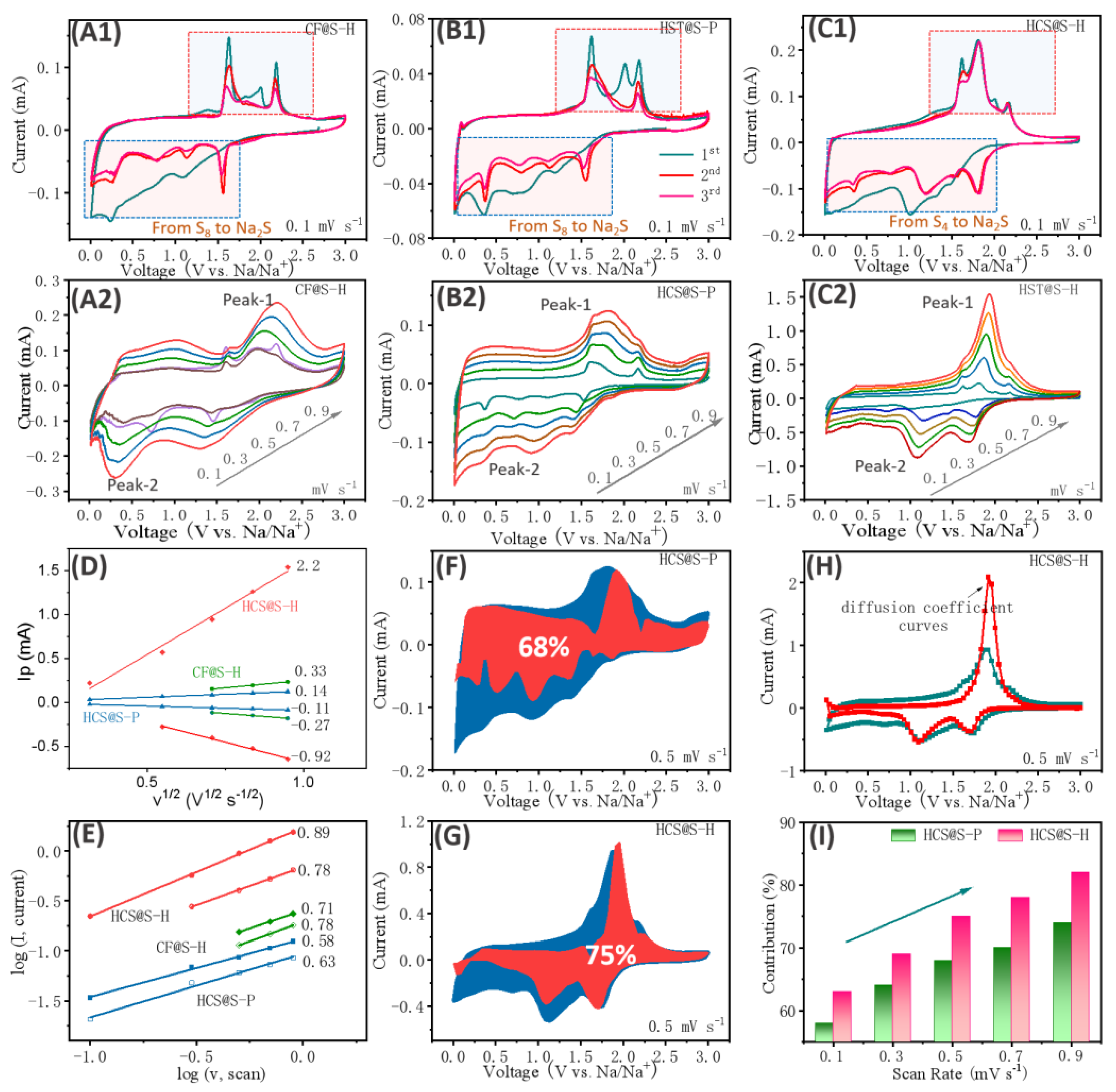
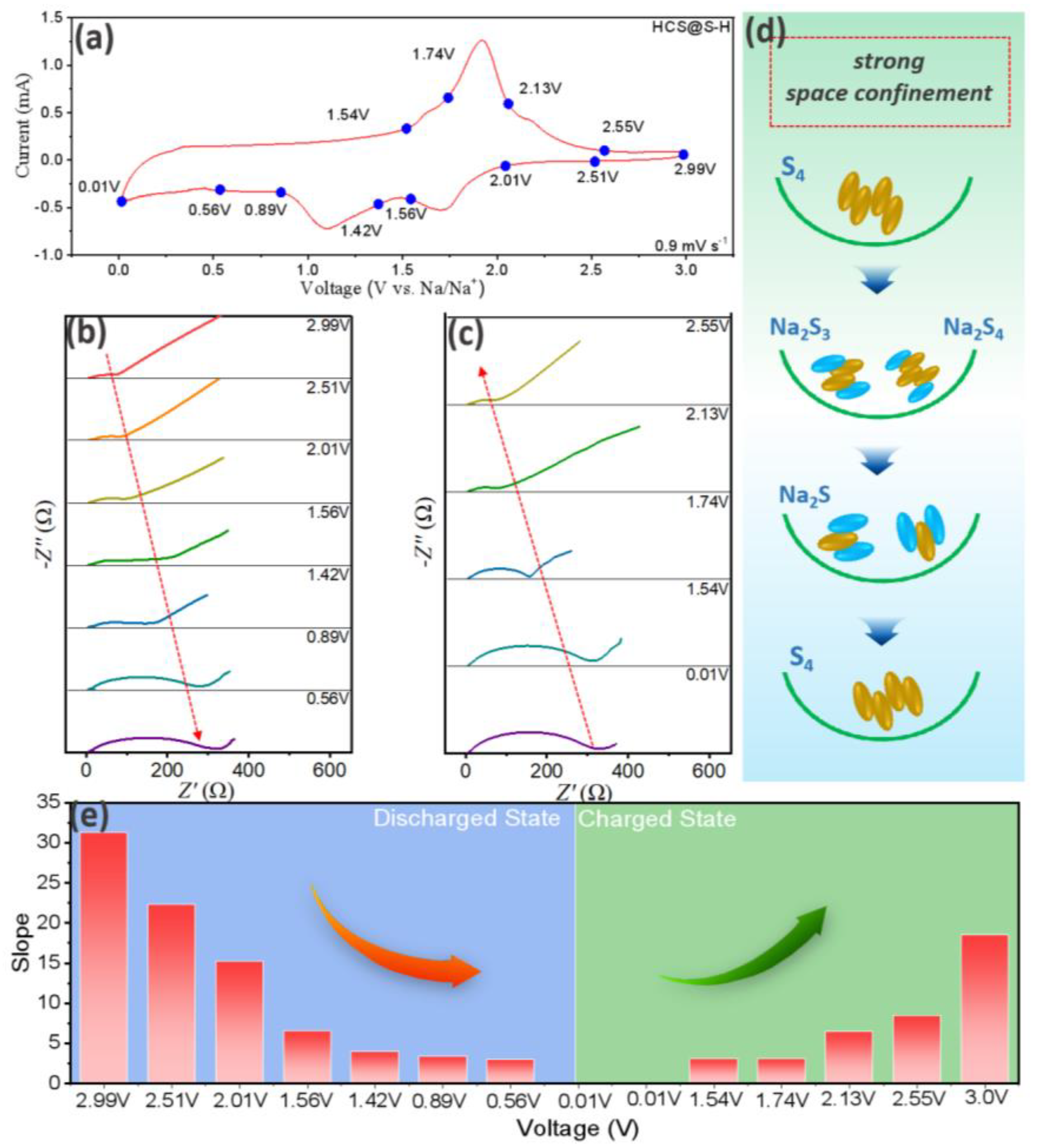
| Discharge State (V) | 2.99 | 2.51 | 2.01 | 1.56 | 1.42 | 0.89 | 0.56 |
|---|---|---|---|---|---|---|---|
| Diffusion coefficients (10−14 cm2 s−1) | 0.95 | 1.86 | 3.99 | 22.1 | 58 | 82 | 104 |
| Charge State (V) | 0.01 | 1.54 | 1.74 | 2.13 | 2.55 | ||
| Diffusion coefficients (10−14 cm2 s−1) | 100.3 | 97.6 | 22.3 | 13.7 | 2.7 |
Publisher’s Note: MDPI stays neutral with regard to jurisdictional claims in published maps and institutional affiliations. |
© 2022 by the authors. Licensee MDPI, Basel, Switzerland. This article is an open access article distributed under the terms and conditions of the Creative Commons Attribution (CC BY) license (https://creativecommons.org/licenses/by/4.0/).
Share and Cite
Wang, G.; Chen, Y.; Yuan, S.; Ge, P. Designing Hollow Carbon Sphere with Hierarchal Porous for Na-S Systems with Ultra-Long Cycling Stabilities. Molecules 2022, 27, 5880. https://doi.org/10.3390/molecules27185880
Wang G, Chen Y, Yuan S, Ge P. Designing Hollow Carbon Sphere with Hierarchal Porous for Na-S Systems with Ultra-Long Cycling Stabilities. Molecules. 2022; 27(18):5880. https://doi.org/10.3390/molecules27185880
Chicago/Turabian StyleWang, Gongke, Yumeng Chen, Shaohui Yuan, and Peng Ge. 2022. "Designing Hollow Carbon Sphere with Hierarchal Porous for Na-S Systems with Ultra-Long Cycling Stabilities" Molecules 27, no. 18: 5880. https://doi.org/10.3390/molecules27185880