Article

An Integrated Electrochemical System for Synergistic Cathodic Nitrate Reduction and Anodic Sulfite Oxidation

1
Tianjin Key Laboratory of Chemical Process Safety, Hebei Collaborative Innovation Center of Modern Marine Chemical Technology, Engineering Research Center of Seawater Utilization of Ministry of Education, School of Chemical Engineering and Technology, Hebei University of Technology, Tianjin 300130, China
2
Department of Chemical and Biochemical Engineering, Western University, London, ON N6A 5B9, Canada
*
Authors to whom correspondence should be addressed.
Molecules 2023, 28(12), 4666; https://doi.org/10.3390/molecules28124666
Submission received: 17 May 2023 / Revised: 7 June 2023 / Accepted: 7 June 2023 / Published: 9 June 2023
(This article belongs to the Special Issue Wastewater Treatment: Functional Materials and Advanced Technology)

Abstract

:
Electrochemical reduction of nitrate has broad application prospects. However, in traditional electrochemical reduction of nitrate, the low value of oxygen produced by the anodic oxygen evolution reaction and the high overpotential limit its application. Seeking a more valuable and faster anodic reaction to form a cathode–anode integrated system with nitrate reaction can effectively accelerate the reaction rate of the cathode and anode, and improve the utilization of electrical energy. Sulfite, as a pollutant after wet desulfurization, has faster reaction kinetics in its oxidation reaction compared to the oxygen evolution reaction. Therefore, this study proposes an integrated cathodic nitrate reduction and anodic sulfite oxidation system. The effect of operating parameters (cathode potential, initial NO3–N concentration, and initial SO32−–S concentration) on the integrated system was studied. Under the optimal operating parameters, the nitrate reduction rate in the integrated system reached 93.26% within 1 h, and the sulfite oxidation rate reached 94.64%. Compared with the nitrate reduction rate (91.26%) and sulfite oxidation rate (53.33%) in the separate system, the integrated system had a significant synergistic effect. This work provides a reference for solving nitrate and sulfite pollution, and promotes the application and development of electrochemical cathode–anode integrated technology.

1. Introduction

In recent years, accelerated industrialization and increasing human activities have led to severe nitrate pollution [1]. Compared with other techniques, such as biological and adsorption methods, the electrochemical reduction of nitrate technology has the advantages of fast removal rate, low cost, and no chemical additives [2,3,4]. It can directly convert harmful nitrate into valuable ammonia, making it a promising nitrate treatment technology. In the traditional electrochemical reduction of nitrate process, the anodic half-reaction is the oxygen evolution reaction (OER), and the economic value of oxygen is limited, so it is usually directly released into the air. In addition, the occurrence of OER requires a high overpotential, which to some extent limits the nitrate reduction rate and causes energy waste [5]. Up to now, researchers have always been keen to develop new materials to obtain higher nitrate reduction rates and product selectivity in exploring the electrochemical reduction of nitrate, and there is almost no research focusing on the application of anodic reactions.
Seeking more valuable anodic reactions to match with nitrate reduction reactions to form an integrated cathodic reduction–anodic oxidation system is highly desirable. In contrast to a single anode or cathode reaction, the integrated cathode reduction–anode oxidation system simultaneously focuses on the anode and cathode reactions, achieving matching reaction rates in a unit system [6]. As a result, the electrochemical cathode–anode integrated system has significant advantages: (1) the matching reaction between the cathode and anode synergistically improves the reaction rates; (2) integrated cathode–anode can simultaneously treat two systems, significantly reducing process costs; and (3) cathode–anode coupling replaces the hydrogen evolution reaction (HER) and oxygen evolution reaction (OER) in separate oxidation and reduction processes, improving energy utilization efficiency [7,8,9].
Sulfite is the main product after wet desulfurization; excess sulfite will cause water and soil pollution, decomposition will release SO2 again, and timely oxidation of sulfite to sulfate can effectively avoid secondary pollution [10,11]. Compared to OER, the oxidation reaction of sulfite (SOR) generated in the desulfurization process exhibits faster kinetics [9,12]. Therefore, by combining cathodic nitrate reduction with anodic sulfite oxidation through electrochemical reactions, synergistic efficiency can be achieved in treating wastewater containing nitrate and sulfite.
In this study, the anodic sulfite oxidation reaction (SOR) was employed to replace the OER, and an electrochemical system integrating cathodic NO3RR with anodic SOR was constructed for the synergistic treatment of both wastewaters. The optimal treatment conditions of the coupled system were determined by investigating the influencing factors including the cathodic potential, initial nitrate concentration, and initial sulfite concentration. The development of this integrated system could provide valuable insights into the development and applications of synergistic electrochemical technology.

2. Results and Discussion

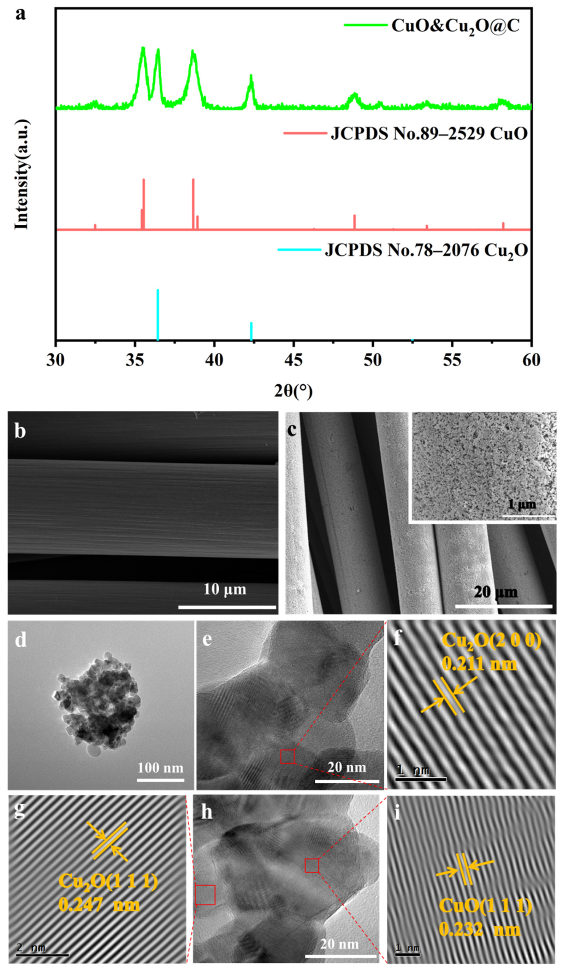
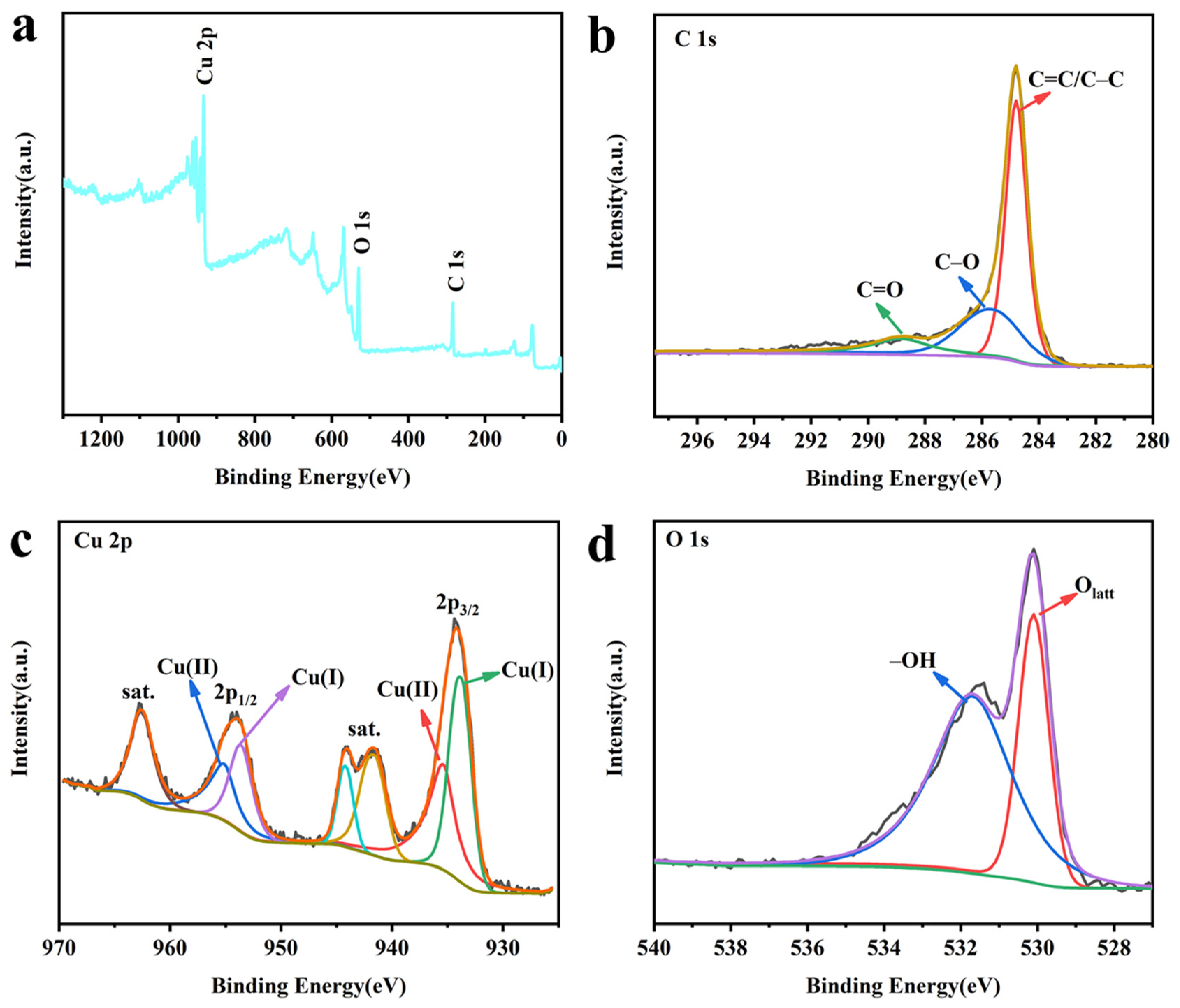
2.1. Characterizations of CuO&Cu2O@C Electrode

The physical phases of the constructed electrode were analyzed via XRD. Figure 1a shows the electrode as a mixed composition of CuO (JCPDS No. 78–2076) and Cu2O (JCPDS No. 89–2529). The strong diffraction peaks at 36.4° and 42.3° are attributed to the (1 1 1) and (2 0 0) crystal planes of Cu2O. The characteristic diffraction peaks at 35.6°, 38.7°, 48.8°, and 58.2° are associated with the (−1 1 1) (1 1 1) (−2 0 2) (2 0 0) crystalline plane of CuO. SEM characterization was used to analyze the surface morphology of the prepared electrode. As shown in Figure 1b,c, the surface of the CC substrate material was uncontaminated, and the constructed electrode surface formed uniform nanoparticles. In order to further clarify the composition and microstructure of the surface nanoparticles, TEM characterization was performed. The TEM image in Figure 1d further shows that nanoparticles were forming on the CC surface. In the HRTEM image (Figure 1e–i), the lattice spacing of the stripes with 0.211 nm, 0.247 nm, and 0.232 nm is attributed to the (2 0 0) and (1 1 1) crystal faces of Cu2O and the (1 1 1) crystal face of CuO [13,14], respectively. This is consistent with the XRD results and fully demonstrates that the composition of the nanoparticles formed on the electrode surface is CuO and Cu2O.
In order to gain a deeper understanding of the nanoparticles on the electrode surface, the element composition and related valence states of the electrode were analyzed via XPS characterization. The XPS full spectrum (Figure 2a) shows the presence of Cu and O elements on the electrode surface, further proving the existence of Cu–related species on the electrode surface. As shown in Figure 2b, the high-resolution C1s spectrum was deconvoluted into three peaks, which could be assigned as C=C/C–C (284.8 eV), C–O (285.6 eV), and C=O (288.4 eV), respectively [13]. The high-resolution Cu 2p spectrum (Figure 2c) contains characteristic peaks of Cu(I) and Cu(II). The peaks at 933.8 eV and 953.6 eV are attributed to the Cu 2p3/2 and Cu 2p1/2 of Cu2O, respectively [15]. A clear satellite peak appears near the peaks at 935.4 eV and 955.1 eV, which is a typical feature of Cu(II) [16]. The high-resolution O 1s spectra (Figure 2d) can be deconvoluted into two peaks, which are hydroxyl oxygen (–OH, 531.7 eV) and lattice oxygen (Olatt, 530.1 eV) [17]. The XPS results are consistent with the TEM results, further proving the synthesis of the CuO&Cu2O@C electrode.

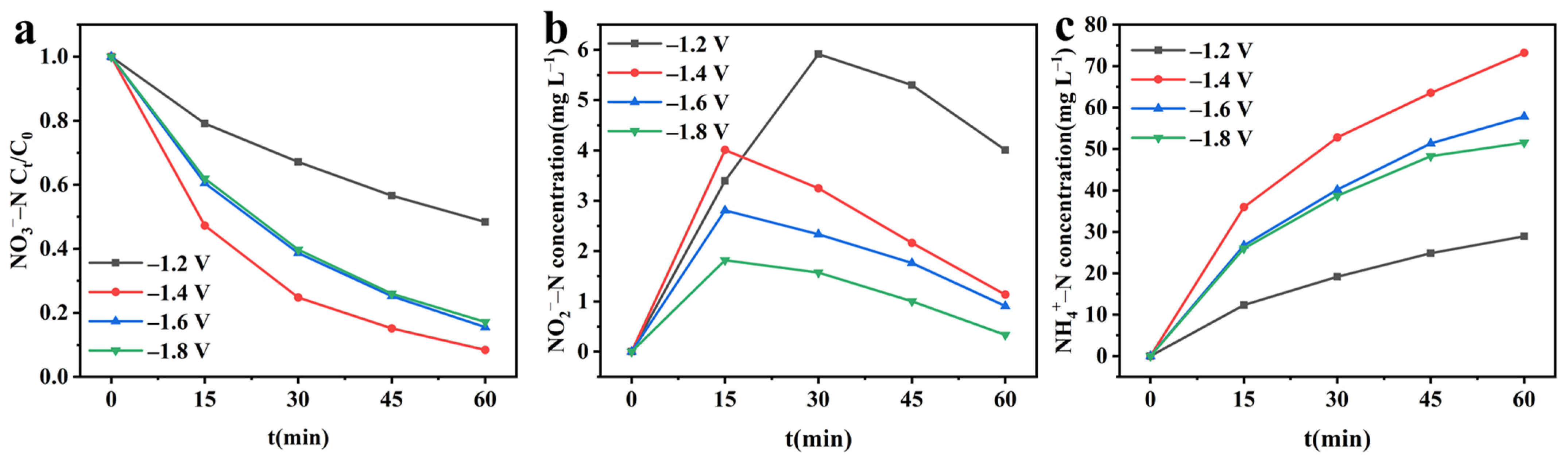
2.2. Electrochemical Reduction of Nitrate

After confirming the structure of the CuO&Cu2O@C electrode, the nitrate reduction activity of this electrode was investigated using different cathodic potentials. Figure 3a shows a significant decay trend of nitrate concentration within 60 min under different potentials, indicating that CuO/Cu2O@C electrode can effectively reduce nitrate. As the potential increases from −1.2 V to −1.8 V, the removal rate shows a volcano-like change. When applying −1.2 V cathodic potential, the removal rate is the lowest, at only 51.59%. This is because at a lower potential, there are not enough electrons provided to reduce nitrate [18]. As the cathodic potential further increases to −1.4 V, the nitrate removal rate increases to 91.61%. This is because the increase in the cathodic potential results in an increase in the amount of electron transfer in the system. When the cathodic potential becomes more negative than −1.4 V, the competitive hydrogen evolution reaction gradually increases, leading to the inhibition of nitrate reduction reaction and a gradual decrease in the removal rate [19]. In order to evaluate the rate of electrochemical reduction of nitrate, the nitrate reduction process was fitted with a pseudo-first-order kinetic model, and the result is shown in Figure S1. R2 indicates that the nitrate reduction conforms to the pseudo-first-order kinetic model and has the fastest reaction rate at −1.4 V, with a kinetic constant (kr) of 2.4386 h−1.
To investigate the reduction products of nitrate, the concentration changes of NO2–N and NH4+–N were continuously detected. In the early stage of the reaction, the concentrations of both NO2–N and NH4+–N showed an increasing trend. However, in the later stages of the reaction, the concentration of NO2–N showed a decreasing trend, while NH4+–N continued to increase (Figure 3b,c). This indicates that NO2–N is the intermediate product of NO3–N reduction, and NH4+–N is the final product of nitrate reduction [20]. The cumulative amount of NH4+–N increases with the increase of cathodic potential, which is consistent with the change law of nitrate removal rate, and also shows a volcano-like shape. This is because the decay of nitrate determines the generation of the final product NH4+–N. At high nitrate removal rates, it allows more NO3–N to be converted to NH4+–N.

2.3. Self-Oxidation and Anodic Electro-Oxidation of Sulfite

To investigate the electro-oxidation performance of SO32−–S on a Pt sheet electrode, a separate study of the electrochemical oxidation of sulfite was conducted, and self-oxidation experiments were conducted to eliminate the effect of air on sulfite oxidation. As shown in Figure 4, the SO32−–S concentration remained essentially constant during the self-oxidation, indicating that SO32−–S was not oxidized by air in the H-type sealed electrolytic cell. In addition, the oxidation of SO32−–S was all electrically driven during the electro-oxidation process. As the cathodic potential increased from −1.2 V to −1.8 V, the oxidation rate of SO32−–S increased from 13.5% to 100%; moreover, the oxidation was complete within 45 min at −1.8 V. This demonstrates that the Pt electrode possessed effective SO32−–S oxidization capability. The electro-oxidation process was fitted with a pseudo-first-order kinetic model, and the kinetic constants obtained for different cathodic potentials indicated that the electro-oxidation process of SO32−–S conforms to the pseudo-first-order kinetic process (Figure S2). As the cathodic potential increases, the kinetic constant of the electro-oxidation process of SO32−–S also increases, which is because at higher potentials, more electrons are generated, thereby accelerating the reaction rate [21].

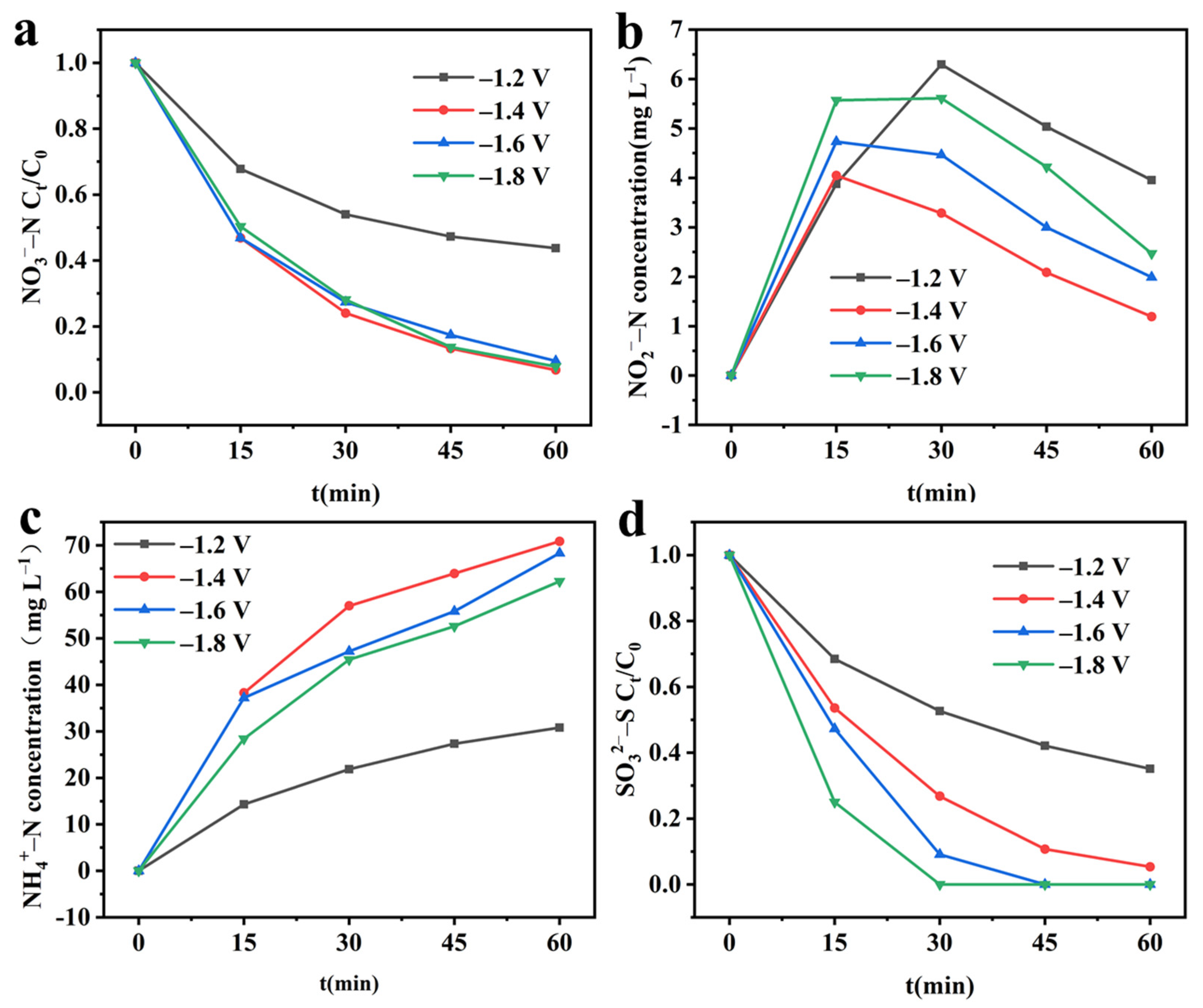
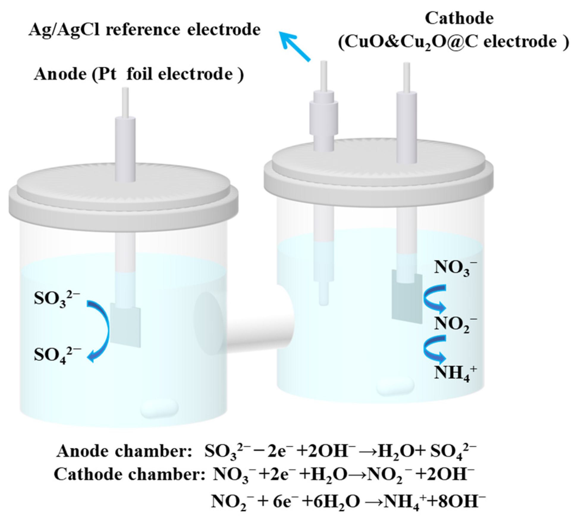
2.4. Integrated Electrochemical System

Based on the single system of electrochemical reduction of nitrate and sulfite oxidation, the two were paired to construct an integrated system to achieve simultaneous treatment of nitrate and sulfite.

2.4.1. Effect of the Applied Cathode Potentials
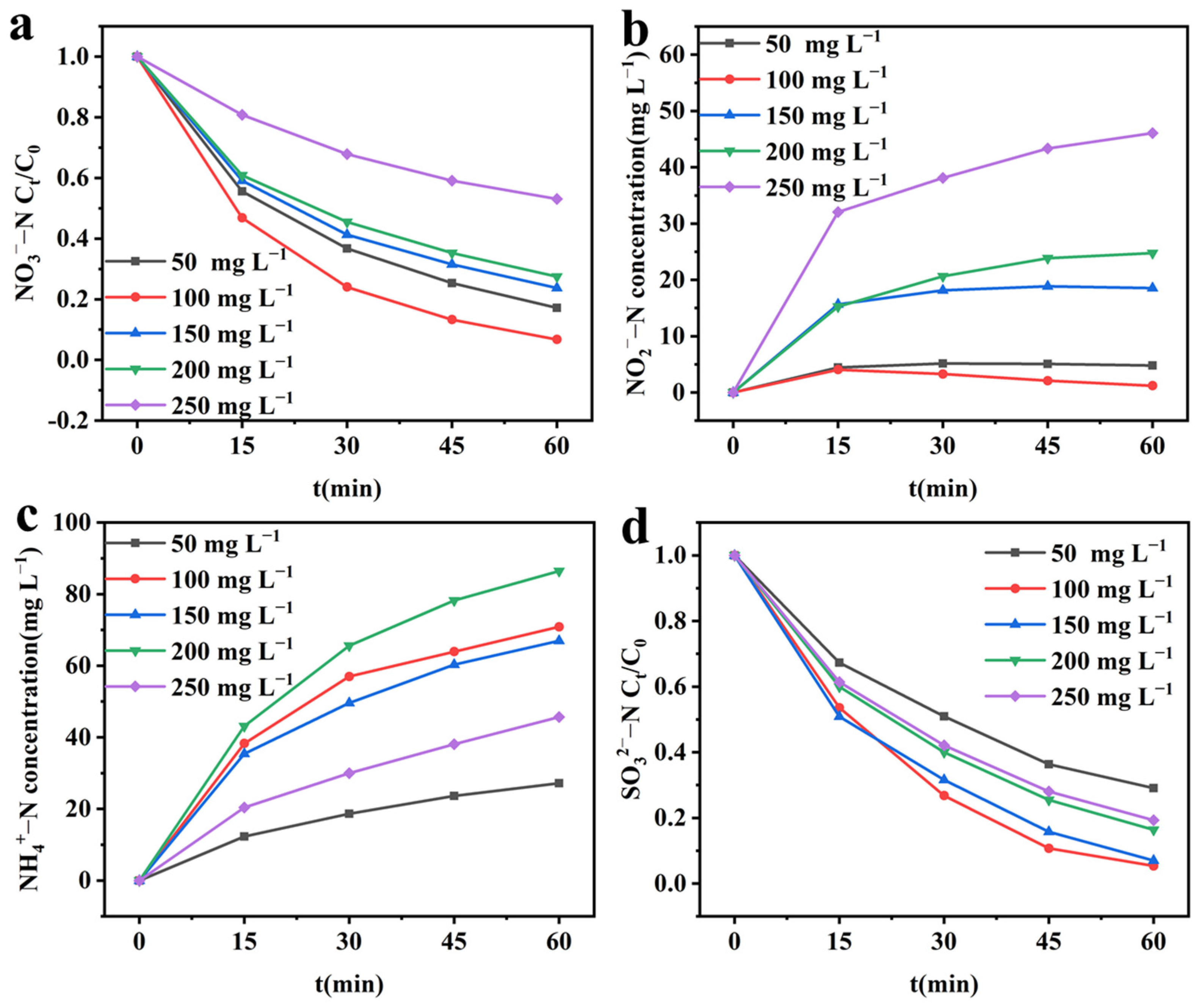
In electrochemical reactions, electrode potential plays a crucial role; therefore, the effect of cathode potential on the integrated system was explored. As shown in Figure 5a, in the integrated system, as the cathode potential increases from −1.2 V to −1.4 V, the NO3–N removal rate increases from 56.28% to 93.26%. Continuing to improve the cathode potential to −1.8 V, the removal rate remains above 90%. The pseudo-first-order kinetic model fitting results for NO3–N reduction (Figure S3a) indicate that NO3–N reduction in the integrated system still belongs to the pseudo-first-order kinetic process. The reaction kinetic constant is highest at a cathode potential of −1.4 V, reaching 2.6622 h−1. Figure 5b,c shows the changes in the products NO2–N and NH4+–N in the integrated system at different potentials. The accumulation of NO2–N remains at a low level of 5 mg L−1 for 1 h at different potentials. The accumulation of NH4+–N increases first and then decreases with the increase of potential, and the highest accumulation was −1.4 V. The reason for the above phenomenon is consistent with that in the single reduction system. At lower potentials, the insufficient electrons produced eventuate NO3–N removal, while at higher potentials, a large amount of hydrogen evolution reaction becomes the primary reaction, hindering the conversion of NO3–N [22]. As shown in Figure 5d, with the increase of cathode potential, the oxidation rate of SO32−–S in the integrated system increases from 64.91% to 100%. As shown in Figure S3b, the oxidation of SO32−–S in the integrated system is also a pseudo-first-order kinetic process.
Table 1 shows the comparison of performance parameters between single electrochemical systems and integrated electrochemical systems. In the integrated system, the removal rate of NO3–N and the oxidation rate of SO32−–S are both improved at different cathode potentials. This implies that the constructed integrated system has synergistic effects. This is because in the single NO3–N reduction system, the anode reaction is oxygen evolution, while in the integrated system, the anode reaction is SO32−–S oxidation, which has lower activation energy and only requires two electrons to complete the reaction, while the oxygen evolution reaction has higher activation energy and requires four electrons. As a result, the oxidation reaction rate SO32−–S is faster in the integrated system, making for a higher reaction current, which promotes the reduction of NO3–N [12]. As for the single sulfite reaction system, the cathode is hydrogen evolution reaction, and the hydrogen evolution reaction rate of the prepared CuO&Cu2O@C electrode is slow. However, in the integrated system, the CuO&Cu2O@C electrode accelerates the reduction rate of NO3–N, and thus elevates the ability of the anode to oxidize SO32−–S. It is worth noting that the enhancement amplitude of NO3–N removal is low at lower potentials of −1.2 V and −1.4 V, while it is significant at higher potentials of −1.6 V and −1.8 V. This is because at high negative potentials, a large amount of hydrogen evolution reaction occurs in the single reduction system, which inhibits the reduction of NO3–N, while at low potentials, the hydrogen evolution reaction does not occur violently [23]. In the integrated system, SO32−–S oxidation inhibits the occurrence of hydrogen evolution reaction [24], and therefore the magnitude of the potentiation varies at different potentials. In addition, the increase of NH4+–N selectivity at different potentials is consistent with the pattern of NO3RR increase. This is due to the fact that NO3RR is directly related to the formation of the final product NH4+–N [25].
By comparing various performance indicators, it can be seen that the NO3–N removal rate is optimal at −1.4 V, the NO2–N selectivity is the lowest, the NH4+–N selectivity is the highest, and although the SO32−–S oxidation rate is not the highest, it still exhibits excellent performance. Therefore, it was reasonable to choose −1.4 V for the subsequent experiments.

2.4.2. Effect of Initial NO3–N Concentration

In integrated electrochemical systems, changes in the half-reaction rate can affect the overall system reaction rate [26]. Changes in the initial NO3–N concentration affect the cathodic reaction NO3RR rate [27], so the effect of different initial NO3–N concentrations on the integrated system was investigated. As shown in Figure 6a and Figure S4a, as the initial NO3–N concentration increases from 50 mg L−1 to 100 mg L−1, the NO3–N removal rate first increases and reaches a maximum of 93.26% at 100 mg L−1, with the fastest reaction rate. As the initial NO3–N concentration continues to increase, the NO3–N removal rate continues to decrease, with the lowest removal rate at 250 mg L−1, only 46.91%, and the slowest reaction rate. The lower removal rate at a low initial NO3–N concentration is due to the limited binding capacity of NO3–N, which leads to a decrease in the effective collision frequency of active molecules [28]. At higher concentrations, the lower NO3–N removal rate is due to the limited catalytic active sites on the CuO&Cu2O@C electrode surface [29]. As shown in Figure 6b,c, with the increase of initial NO3–N concentration, the selectivity of NO2–N first increases and then decreases, while the selectivity of NH4+–N shows the opposite trend. This is because at low initial NO3–N concentrations, the rate of conversion of NO3–N to the intermediate product NO2–N is lower than the rate of conversion of NO2–N to NH4+–N, while at higher initial NO3–N concentrations, the rate of conversion of NO3–N to the intermediate product NO2–N is higher than the rate of conversion of NO2–N to NH4+–N.
As shown in Figure 6d, as the initial NO3–N concentration increases from 50 mg L−1 to 100 mg L−1, the SO32−–S oxidation rate increases from 70.91% to 94.64%. As the initial NO3–N concentration further increases, the SO32−–S oxidation rate gradually decreases and decreases to 80.70% at 250 mg L−1. As shown in Figure S4b, the oxidation kinetic constant ko first increases and then decreases with the rise in initial NO3–N concentration, which is consistent with the changing trend of cathodic reduction NO3–N kinetic constant. This indicates that the change in the cathodic reaction rate will cause the same change trend in the anodic reaction rate, which is due to the mutual matching relationship between the cathodic and anodic reaction rates. When the rates of the two half-reactions do not match, they will decrease simultaneously.
By comparing the NO3–N reduction rate, SO32−–S oxidation rate, NO2–N selectivity, and NH4+–N selectivity, it is easy to find that the initial NO3–N concentration of 100 mg L−1 showed excellent performance in all the above indexes, so it was chosen as the initial NO3–N concentration for the subsequent study.

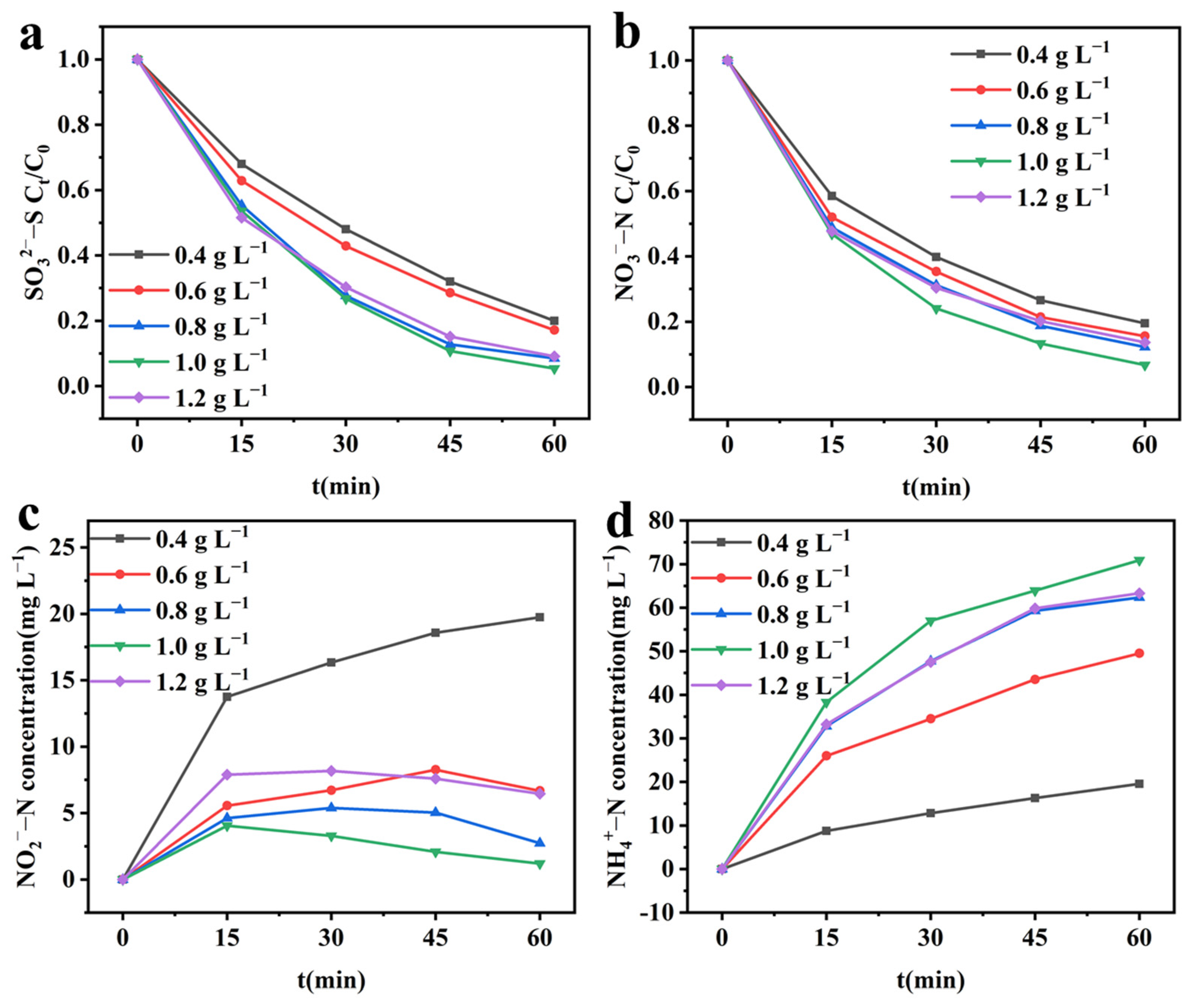
2.4.3. Effect of Initial SO32−–S Concentration on Integrated Electrochemical System

The initial SO32−–S concentration in the anode chamber is closely related to the SOR rate [30], which affects the cathodic reaction rate. Based on this, the effect of initial SO32−–S concentration on the integrated system was investigated. As shown in Figure 7a, as the initial SO32−–S concentration increases from 0.4 g L−1 to 1.0 g L−1, the SO32−–S oxidation rate increases continuously from 80.00% to 94.64%. When the initial SO32−–S concentration is further increased to 1.2 g L−1, the SO32−–S oxidation rate decreases to 90.91%. As the initial SO32−–S concentration increases, the oxidation kinetic constant ko shows a trend of first increasing and then declining (Figure S5a). At concentrations of 0.4, 0.6, 0.8, 1.0, and 1.2 g L−1, the reduction rates of NO3–N are 80.51%, 84.42%, 87.80%, 93.26%, and 86.37%, respectively (Figure 7b). The fitting results of cathodic reduction NO3–N to first-order kinetics show (Figure S5b) that as the initial SO32−–S concentration continuously increases, kr increases from 1.5891 h−1 to 2.6622 h−1 and then decreases to 1.9384 h−1. This changing trend is consistent with the SO32−-S oxidation kinetic constant trend. This once again indicates that at lower initial SO32−–S concentration, the anodic oxidation reaction cannot match the cathodic reduction reaction, resulting in a decrease in the cathodic and anodic reaction rates in the integrated system. As the initial SO32−–S concentration increases, the anodic and cathodic reactions gradually match, resulting in the highest rates of sulfite oxidation and nitrate reduction at an initial SO32−–S concentration of 1.0 g L−1. When the initial SO32−–S concentration continues to increase to 1.2 g L−1, this mismatch reappears, resulting in a decrease in the performance of the integrated system.
Figure 7c,d shows the changes of the products NO2–N and NH4+–N at different initial SO32−–S concentrations, respectively. The accumulation of NO2–N first decreased with the increase of initial SO32−–S concentration, reaching a minimum at 1.0 g L−1, and then increased with the further increase in SO32−–S concentrations. The NH4+–N production showed a trend of increasing and then decreasing, with the highest production at the initial SO32−–S concentration of 1.0 g L−1. This indicates that the decrease in the reaction rate during the cathodic reduction of nitrate leads to the accumulation of intermediate products, affecting the transformation of intermediate products to final products.
In this system, NO3 is converted to NH4+ at the cathode and SO32− is converted to SO42− at the anode. The final products could be recycled via crystallization and utilized to form valuable compounds such as magnesium ammonia phosphate (struvite precipitate, NH4MgPO4·6H2O) [31,32], calcium sulfate (CaSO4), barium sulfate (BaSO4), Ettringite (Ca6Al2(SO4)3(OH)12) [33], etc., thus achieving more effective treatment of nitrate and sulfite in wastewater.

3. Materials and Methods

3.1. Reagents

The reagents in this work are of analytical grade or above and were used without further purification.

3.2. Fabrication of CuO&Cu2O@C Electrode

In this study, a Pt foil (1 cm × 1.5 cm × 0.1 mm) was used as the anode, and a Ag/AgCl electrode was used as the reference electrode. To investigate the accelerating effect of the SOR instead of OER, a highly NO3RR-efficient CuO&Cu2O@C electrode (effective area of 1 cm × 1.5 cm) was synthesized and used as the cathode.
The CuO&Cu2O@C electrode was constructed using a redox strategy based on the previously reported research protocol with modifications [1,34]. Specifically, a carbon cloth (1 cm × 2 cm) was subjected to ultrasound treatment with a mixture of nitric acid (10 wt.% HNO3) and sulfuric acid (10 wt.% H2SO4), acetone, ethanol, and deionized water for 1 h to remove surface impurities. Subsequently, 8 mL of ethylene glycol, 8 mL of ethanol, and 3 mmol Cu(NO3)2·3H2O were added to a beaker, and the mixture was thoroughly stirred for 1 h to obtain a transparent blue solution. The pretreated carbon cloth was then immersed in the solution for 4 h, and the entire system was transferred to a 25 mL hydrothermal autoclave and reacted at 180 ℃ for 6 h. After the hydrothermal autoclave was cooled to room temperature, the modified carbon cloth was taken out and sonicated in anhydrous ethanol for 15 s, washed several times with water and ethanol, and dried at 60 ℃ in a vacuum oven for 6 h. Finally, the modified carbon cloth was annealed in a muffle furnace at 350 °C for 2 h to obtain the CuO&Cu2O@C electrode.

3.3. Characterizations

X-ray diffraction (XRD, Bruker, Billerica, MA, USA, D8 FOCUS) was used to analyze the physical phase of the electrode. Scanning electron microscopy (SEM, Zeiss, Oberkochen, Germany, G300) and transmission electron microscopy (TEM, FEI, Tecnai G2 F30) were used to record the morphology and crystal lattice information. X-ray photoelectron spectroscopy (XPS, Thermo, Waltham, MA, USA, ESCALAB 250XI, Al Kα) was applied to examine the chemical and binding states of the CuO&Cu2O@C electrode. The binding energy was calibrated using C 1s spectrum at 284.8 eV.

3.4. Batch Experiments

Batch experiments were conducted in an H-type electrolytic cell (Figure 8), with an anode and cathode distance of 8 cm, separated by a Nafion 117 proton exchange membrane, and using Ag/AgCl as the reference electrode.

3.4.1. Single Electrochemical Reduction of Nitrate

In a three-electrode system, a mixture of 30 mL of 100 mg L−1 (K)NO3–N and 0.5 mol L−1 K2SO4 solution was added to the cathode chamber, and 30 mL 0.5 mol L−1 K2SO4 solution was added to the anode chamber. The cathodic potentials of −1.2 V, −1.4 V, −1.6 V, and −1.8 V (vs. Ag/AgCl) were applied to drive the reactions to study the electrochemical reduction of nitrate systems alone.

3.4.2. Self-Oxidation and Single Electro-Oxidation of Sulfite

In a three-electrode system, 30 mL of 0.5 mol L−1 K2SO4 solution was added to the cathode chamber, and a mixture of 30 mL of 1.0 g L−1 (K2)SO32−–S and 0.5 mol L−1 K2SO4 solution was added to the anode chamber. The study on sulfite self-oxidation was conducted without applying an electric current. In the single electrochemical oxidation of sulfite, in order to investigate the oxidation rate in the absence of nitrate reduction reaction, the aforementioned potential was still used for the study.

3.4.3. Integrated Electrochemical Batch Experiments

The cathode compartment was filled with a mixed solution of 30 mL of 1.0 g L−1 (K2)SO32−–S and 100 mg L−1 (K)NO3–N, while the anode compartment was filled with 30 mL of 1.0 g L−1 (K2)SO32−–S and 0.5 mol L−1 K2SO4 mixed solution. Both the cathode and anode compartments were stirred at 300 rpm, and the batch experiments were conducted for 1 h. At a time interval of 15 min, 0.4 mL of solution was taken from the cathode compartment to detect the concentrations of NO3–N, NO2–N, and NH4+–N, and 1 mL of solution was taken from the anode compartment to detect the concentration of SO32−–S. The method for the determination of ion concentrations and calculation for removal rate and selectivity were illustrated in the supporting information. Additionally, this study investigated the effects of different cathode potentials (−1.2 V, −1.4 V, −1.6 V, −1.8 V vs. Ag/AgCl), initial NO3–N concentration (50 mg L−1, 100 mg L−1, 150 mg L−1, 200 mg L−1, 250 mg L−1), and initial SO32−–S concentration (0.4 g L−1, 0.6 g L−1, 0.8 g L−1, 1.0 g L−1, 1.2 g L−1) on the integrated system.

4. Conclusions

In summary, a cathode material for efficient electrochemical reduction of nitrate was designed, which achieved effective removal of nitrate. However, in the single reduction process, the anodic oxygen evolution reaction (OER) has certain limitations and wastes energy. Therefore, an electrochemical reduction of nitrate integrated with a sulfite oxidation system was developed. By exploring the operating parameters (cathode potential, initial nitrate concentration, and initial sulfite concentration) in the integrated system, the results show that compared with the single reduction and oxidation system, the integrated system has a faster reaction rate while achieving simultaneous treatment of harmful nitrate and sulfite. At −1.4 V (vs. Ag/AgCl) cathodic potential, 100 mg L−1 initial nitrate, and 1.0 g L−1 sulfite concentrations, the nitrate removal rate and sulfite oxidation rate within 1 h reached 93.26% and 94.64%, respectively. This study provides more references for solving the mutual constraint between half-reactions.

Supplementary Materials

The following supporting information can be downloaded at: https://www.mdpi.com/article/10.3390/molecules28124666/s1, Figure S1: Fitting results of pseudo-first-order kinetic model for single electrochemical reduction of nitrate at different potentials. Figure S2. Fitting results of pseudo-first-order kinetic model for single electrochemical oxidation of sulfite at different potentials. Figure S3. Fitting results of pseudo-first-order kinetic model for integrated electrochemical system at different potentials; (a) nitrate reduction reaction; (b) sulfite oxidation reaction. Figure S4. Fitting results of pseudo-first-order kinetic model for integrated electrochemical system at different initial NO3–N concentrations; (a) nitrate reduction reaction; (b) sulfite oxidation reaction. Figure S5. Fitting results of pseudo-first-order kinetic model for integrated electrochemical system at different initial SO32−–S concentrations; (a) sulfite oxidation reaction; (b) nitrate reduction reaction.

Author Contributions

Conceptualization, B.C., Y.Z. and S.R.; Methodology, B.C., S.W., Y.Z. and S.R.; Validation, B.C., S.W. and X.G.; Investigation, X.G. and S.R.; Resources, Y.Z.; Writing—original draft, B.C.; Writing—review & editing, Y.Z. and S.R.; Visualization, S.W. and X.G.; Supervision, Y.Z.; Project administration, Y.Z.; Funding acquisition, Y.Z. All authors have read and agreed to the published version of the manuscript.

Funding

This work was funded by the Tianjin Science and Technology Project (20JCZDJC00450), Natural Science Foundation of Hebei Province (B2020202029), Central Guidance on Local Science and Technology Development Fund of Hebei Province (226Z3102G), and Fundamental Research Funds of Hebei University of Technology (JBKYTD2001).

Institutional Review Board Statement

Not applicable.

Informed Consent Statement

Not applicable.

Data Availability Statement

The datasets used and analyzed in the present study are available from the corresponding author upon reasonable request.

Conflicts of Interest

The authors declare no conflict of interest.

Sample Availability

Samples of the compounds are available from the authors.

References

  1. Chen, M.; Huang, X.; Wang, N.; Wang, T.; Yang, J.; Wei, Y.; Dao, X.; Zhou, L.; Hao, H. Cu2O Nanoparticles Modified BiO2−x Nanosheets for Efficient Electrochemical Reduction of Nitrate-N and Nitrobenzene from Wastewater. Sep. Purif. Technol. 2022, 289, 120728. [Google Scholar] [CrossRef]
  2. Yao, D.; Tang, C.; Wang, P.; Cheng, H.; Jin, H.; Ding, L.X.; Qiao, S.Z. Electrocatalytic Green Ammonia Production beyond Ambient Aqueous Nitrogen Reduction. Chem. Eng. Sci. 2022, 257, 117735. [Google Scholar] [CrossRef]
  3. Ren, T.; Ren, K.; Wang, M.; Liu, M.; Wang, Z.; Wang, H.; Li, X.; Wang, L.; Xu, Y. Concave-Convex Surface Oxide Layers over Copper Nanowires Boost Electrochemical Nitrate-to-Ammonia Conversion. Chem. Eng. J. 2021, 426, 130759. [Google Scholar] [CrossRef]
  4. Yuan, S.; Xue, Y.; Ma, R.; Ma, Q.; Chen, Y.; Fan, J. Advances in Iron-Based Electrocatalysts for Nitrate Reduction. Sci. Total Environ. 2023, 866, 161444. [Google Scholar] [CrossRef]
  5. Vass, Á.; Kormányos, A.; Kószo, Z.; Endrődi, B.; Janáky, C. Anode Catalysts in CO2 Electrolysis: Challenges and Untapped Opportunities. ACS Catal. 2022, 12, 1037–1051. [Google Scholar] [CrossRef]
  6. Zou, J.P.; Chen, Y.; Liu, S.S.; Xing, Q.J.; Dong, W.H.; Luo, X.B.; Dai, W.L.; Xiao, X.; Luo, J.M.; Crittenden, J. Electrochemical Oxidation and Advanced Oxidation Processes Using a 3D Hexagonal Co3O4 Array Anode for 4-Nitrophenol Decomposition Coupled with Simultaneous CO2 Conversion to Liquid Fuels via a Flower-like CuO Cathode. Water Res. 2019, 150, 330–339. [Google Scholar] [CrossRef]
  7. Li, D.; Yang, J.; Lian, J.; Yan, J.; Liu, S. Recent Advances in Paired Electrolysis Coupling CO2 Reduction with Alternative Oxidation Reactions. J. Energy Chem. 2023, 77, 406–419. [Google Scholar] [CrossRef]
  8. Ali, I.; Barros de Souza, A.; De Laet, S.; Van Eyck, K.; Dewil, R. Anodic Oxidation of Sulfamethoxazole Paired to Cathodic Hydrogen Peroxide Production. Chemosphere 2023, 319, 137984. [Google Scholar] [CrossRef]
  9. Chen, S.; Zhou, W.; Ding, Y.; Zhao, G.B.; Gao, J.H. Energy-Saving Cathodic Hydrogen Production Enabled by Anodic Oxidation of Aqueous Sodium Sulfite Solutions. Energy Fuels 2020, 34, 9058–9063. [Google Scholar] [CrossRef]
  10. Wang, L.; Wang, J.; Xu, P.; Li, Q.; Zhang, W.; Cui, S. Selectivity of Transition Metal Catalysts in Promoting the Oxidation of Solid Sulfites in Flue Gas Desulfurization. Appl. Catal. A Gen. 2015, 508, 52–60. [Google Scholar] [CrossRef]
  11. Wang, L.; Xing, L.; Liu, J.; Qi, T.; Zhang, S.; Ma, Y.; Ning, P. Construction of Lattice-Confined Co-MCM-48 for Boosting Sulfite Oxidation in Wet Desulfuration. Chem. Eng. J. 2021, 407, 127210. [Google Scholar] [CrossRef]
  12. Han, J.; Cheng, H.; Zhang, L.; Fu, H.; Chen, J. Trash to Treasure: Use Flue Gas SO2 to Produce H2 via a Photoelectrochemical Process. Chem. Eng. J. 2018, 335, 231–235. [Google Scholar] [CrossRef]
  13. Dubale, A.A.; Ahmed, I.N.; Zhang, Y.J.; Yang, X.L.; Xie, M.H. A Facile Strategy for Fabricating C@Cu2O/CuO Composite for Efficient Photochemical Hydrogen Production with High External Quantum Efficiency. Appl. Surf. Sci. 2020, 534, 147582. [Google Scholar] [CrossRef]
  14. Du, F.; Cui, G.H.; Yang, B.L.; Zhang, D.S.; Song, R.F.; Li, Z.X. Ingenious Design of One Mixed-Valence Dual-Net Copper Metal-Organic Framework for Deriving Cu2O/CuO Heterojunction with Highly Electrocatalytic Performances from NO3 to NH3. J. Power Sources 2022, 543, 231832. [Google Scholar] [CrossRef]
  15. Liang, X.; Chen, X.; Xiang, Z.; Yan, R.; Xi, H.; Bian, T.; Zhang, J.; Zhao, J.; Cai, Q.; Wang, H. Design and Synthesis of Surface-Controlled CuOx /RGO Nanocomposites with Unusually High Efficiency in Catalytic Conversion of Organic Reactants in the Presence of NaBH 4. Appl. Surf. Sci. 2018, 459, 716–722. [Google Scholar] [CrossRef]
  16. Moghanlou, A.O.; Sadr, M.H.; Bezaatpour, A.; Salimi, F.; Yosefi, M. RGO/Cu2O-CuO Nanocomposite as a Visible-Light Assisted Photocatalyst for Reduction of Organic Nitro Groups to Amines. Mol. Catal. 2021, 516, 111997. [Google Scholar] [CrossRef]
  17. Li, J.; Guo, J.; Zhang, J.; Sun, Z.; Gao, J. Surface Etching and Photodeposition Nanostructures Core-Shell Cu2O@CuO-Ag with S-Scheme Heterojunction for High Efficiency Photocatalysis. Surf. Interfaces 2022, 34, 102308. [Google Scholar] [CrossRef]
  18. Jiang, G.; Peng, M.; Hu, L.; Ouyang, J.; Lv, X.; Yang, Z.; Liang, X.; Liu, Y.; Liu, H. Electron-Deficient Cuδ+ Stabilized by Interfacial Cu–O-Al Bonding for Accelerating Electrocatalytic Nitrate Conversion. Chem. Eng. J. 2022, 435, 134853. [Google Scholar] [CrossRef]
  19. Xu, Y.; Ren, K.; Ren, T.; Wang, M.; Wang, Z.; Li, X.; Wang, L.; Wang, H. Ultralow-Content Pd in-Situ Incorporation Mediated Hierarchical Defects in Corner-Etched Cu2O Octahedra for Enhanced Electrocatalytic Nitrate Reduction to Ammonia. Appl. Catal. B Environ. 2022, 306, 121094. [Google Scholar] [CrossRef]
  20. He, L.; Yao, F.; Zhong, Y.; Tan, C.; Hou, K.; Pi, Z.; Chen, S.; Li, X.; Yang, Q. Achieving High-Performance Electrocatalytic Reduction of Nitrate by N-Rich Carbon-Encapsulated Ni-Cu Bimetallic Nanoparticles Supported Nickel Foam Electrode. J. Hazard. Mater. 2022, 436, 129253. [Google Scholar] [CrossRef]
  21. Lăboșel, M.A.; Dima, G.D.; Duca, D.A.; Vaszilcsin, N.; Laurentiu Dan, M. Anodic Sulphite Oxidation on Lead Electrode in a Neutral Environment. Mater. Today Proc. 2022, 78, 302–307. [Google Scholar] [CrossRef]
  22. Zhou, J.; Pan, F.; Yao, Q.; Zhu, Y.; Ma, H.; Niu, J.; Xie, J. Achieving Efficient and Stable Electrochemical Nitrate Removal by In-Situ Reconstruction of Cu2O/Cu Electroactive Nanocatalysts on Cu Foam. Appl. Catal. B Environ. 2022, 317, 121811. [Google Scholar] [CrossRef]
  23. Yao, F.; Jia, M.; Yang, Q.; Chen, F.; Zhong, Y.; Chen, S.; He, L.; Pi, Z.; Hou, K.; Wang, D.; et al. Highly Selective Electrochemical Nitrate Reduction Using Copper Phosphide Self-Supported Copper Foam Electrode: Performance, Mechanism, and Application. Water Res. 2021, 193, 116881. [Google Scholar] [CrossRef]
  24. Kong, Y.; Wang, L.; Jiang, H.; Li, F.; Zhao, T.; Zhuo, M.; Chen, Q.; Mao, M.; Xu, Y. Design of Counter Oxidation vs. CO2 Electroreduction for Efficient Formate Production on a Tin Cathode. J. Electroanal. Chem. 2019, 847, 113264. [Google Scholar] [CrossRef]
  25. Zhu, D.; Li, G.; Yan, X.; Geng, C.; Gao, L. Electrochemical Nitrate Reduction to High-Value Ammonia on Two-Dimensional Molybdenum Carbide Nanosheets for Nitrate-Containing Wastewater Upcycling. Sci. Total Environ. 2023, 878, 163145. [Google Scholar] [CrossRef]
  26. Bharath, G.; Hai, A.; Rambabu, K.; Kallem, P.; Haija, M.A.; Banat, F.; Theerthagiri, J.; Choi, M.Y. Fabrication of Pd/MnFe2O4 Bifunctional 2-D Nanosheets to Enhance the Yield of HCOOH from CO2 Cathodic Reduction Paired with Anodic Oxidation to CH3OH. Fuel 2022, 311, 122619. [Google Scholar] [CrossRef]
  27. Chen, M.; Bi, J.; Huang, X.; Wang, T.; Wang, Z.; Hao, H. Bi2O3 Nanosheets Arrays In-Situ Decorated on Carbon Cloth for Efficient Electrochemical Reduction of Nitrate. Chemosphere 2021, 278, 130386. [Google Scholar] [CrossRef]
  28. Fang, X.; Tan, L.; Luo, H.; Jiang, F.; Chen, H. Efficient Electrochemical Reduction of Nitrate by Bimetallic Cu-Fe Phosphide Derived from Prussian Blue Analogue. Colloids Surf. A Physicochem. Eng. Asp. 2023, 658, 130678. [Google Scholar] [CrossRef]
  29. Niu, Q.; Yang, S.; Song, Z.; Liu, C.; Li, Z.; Wang, X.; Song, L. Fabrication of Efficient and Robust Fe0/Ni2P/CC Composite and the Employment for Electrochemical Reduction of Nitrate. J. Environ. Chem. Eng. 2021, 9, 106412. [Google Scholar] [CrossRef]
  30. Enache, A.F.; Dan, M.L.; Muntean, R.; Vaszilcsin, N. New Electrodes Based on Pt-Co Alloys Used as Anodic Materials for Sulphite Oxidation in Alkaline Fuel Cells. IOP Conf. Ser. Mater. Sci. Eng. 2018, 416, 012072. [Google Scholar] [CrossRef]
  31. Yan, X.; He, L.; Zhang, W.; Chen, W.; Wu, J.; Yang, N.; Cai, X.; Li, L.; Yan, L.; Rao, P. Efficient Ammonia-Nitrogen Removal and Recovery from Wastewater via the Continuous Flat-Sheet Gas-Permeable Membranes Reactor Pretreatment. J. Water Process Eng. 2023, 52, 103571. [Google Scholar] [CrossRef]
  32. Lee, G.; Kim, K.; Chung, J.; Han, J.I. Electrochemical Ammonia Accumulation and Recovery from Ammonia-Rich Livestock Wastewater. Chemosphere 2021, 270, 128631. [Google Scholar] [CrossRef] [PubMed]
  33. Chatla, A.; Almanassra, I.W.; Abushawish, A.; Laoui, T.; Alawadhi, H.; Atieh, M.A.; Ghaffour, N. Sulphate Removal from Aqueous Solutions: State-of-the-Art Technologies and Future Research Trends. Desalination 2023, 558, 116615. [Google Scholar] [CrossRef]
  34. Shi, Y.; Xu, L.; Chen, M.; Yang, B.; Cheng, G.; Wu, C.e.; Miao, Z.; Wang, N.; Hu, X. Fabricating Cu2O-CuO Submicron-Cubes for Efficient Catalytic CO Oxidation: The Significant Effect of Heterojunction Interface. J. Ind. Eng. Chem. 2022, 105, 324–336. [Google Scholar] [CrossRef]
Figure 1. (a) XRD patterns of CuO&Cu2O@C; (b) SEM image of CC; (c) SEM images of CuO&Cu2O@C; (d) TEM image; (ei) HRTEM images of CuO&Cu2O@C.
Molecules 28 04666 g001
Figure 2. (a) XPS full-range spectra; (b) high-resolution Cu 1s; (c) high-resolution Cu 2p; (d) high-resolution O 1s of CuO&Cu2O@C.
Molecules 28 04666 g002
Figure 3. Electrochemical reduction of nitrate at different cathodic potentials. (a) NO3–N concentration; (b) NO2–N concentration; (c) NH4+–N concentration.
Molecules 28 04666 g003
Figure 4. SO32−–S concentration during self-oxidation and electro-oxidation at different potentials.
Molecules 28 04666 g004
Figure 5. Effect of cathodic potential on the performance of integrated electrochemical systems. (a) NO3–N concentration; (b) NO2–N concentration; (c) NH4+–N concentration; (d) SO32−–S concentration. Experimental conditions: initial NO3–N concentration = 100 mg L−1; initial SO32−–S concentration = 1.0 g L−1.
Molecules 28 04666 g005
Figure 6. Effect of initial NO3–N concentration on the performance of integrated electrochemical systems. (a) NO3–N concentration; (b) NO2–N concentration; (c) NH4+–N concentration; (d) SO32−–S concentration. Experimental conditions: cathodic potential = −1.4 V; initial SO32−–S concentration = 1.0 g L−1.
Molecules 28 04666 g006
Figure 7. Effect of initial SO32−–S concentration on the performance of integrated electrochemical systems. (a) SO32−–S concentration; (b) NO3–N concentration; (c) NO2–N concentration; (d) NH4+–N concentration. Experimental conditions: cathodic potential = −1.4 V; initial NO3–N concentration = 100 mg L−1.
Molecules 28 04666 g007
Figure 8. H-type electrolytic cell and SO32−, NO3 transformation process.
Molecules 28 04666 g008
Table 1. Comparison of single system and integrated system performance parameters.
R (NO3–N)/%S (NO2–N)/%S (NH4+–N)/%O (SO32−–S)/%
SingleIntegratedSingleIntegratedSingleIntegrateSingleIntegrated
−1.2 V51.5956.287.646.8055.1453.5013.1564.91
−1.4 V91.6193.261.221.2578.4174.9053.3394.64
−1.6 V84.4690.461.052.1067.2173.2081.82100.00
−1.8 V82.8992.190.402.6061.3966.70100.00100.00
Disclaimer/Publisher’s Note: The statements, opinions and data contained in all publications are solely those of the individual author(s) and contributor(s) and not of MDPI and/or the editor(s). MDPI and/or the editor(s) disclaim responsibility for any injury to people or property resulting from any ideas, methods, instructions or products referred to in the content.

