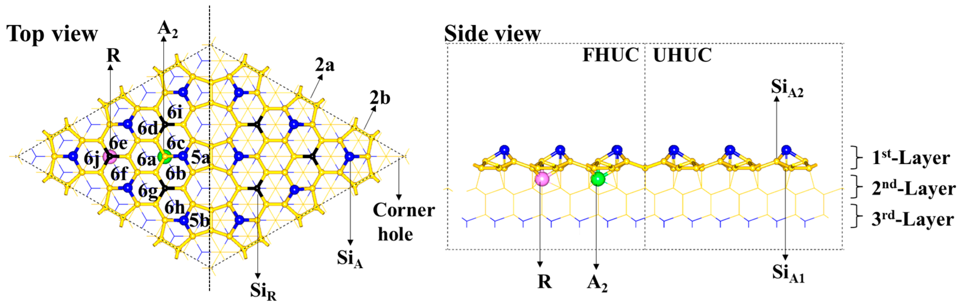
2.1. The DASF Surface Structure
The DASF model consists of a faulted half-unit cell (FHUC) and an unfaulted half-unit cell (UHUC), as is shown in
Scheme 1. Within each unit cell, there are three rest atoms (represented by Si
R) and six adatoms (represented by Si
A). The Si
R atoms are 0.81 Å lower than the Si
A atoms. The Si
R and Si
A atoms differ in their coordination environment. The coordination number of the Si
R atom is three and the average Si–Si bond length is 2.41 Å. The coordination number of the Si
A atom is four (coordinated with one Si
A1 atom and three Si
A2 atoms) and the average Si–Si bond length is 2.48 Å. Both the Si
A1 and Si
A2 atoms are four-coordinated but differ in the coordination environment, which is close to a tetrahedron for Si
A1 but greatly distorted from a tetrahedron for Si
A2. The Si
A adatom is nonequivalent sp
3 hybridized and strongly polarized. On the DASF surface, there are two kinds of five-membered rings (represented by
5a and
5b, respectively) and three kinds of six-membered Si rings (represented by
6a for the first kind,
6b~
6g for the second kind, and
6h~
6j for the third kind, respectively), according to symmetry. The main structural difference between the two cells is that the third layer Si atoms (blue lines) are located just below the center of these six-membered Si rings in the FHUC, whereas the second layer Si atoms (yellow lines) are located just below the center of these six-membered Si rings in the UHUC. In addition, there is a hole in the corner of the cell. Along the contacted edge of the two half-unit cells are dimers consisting of two Si atoms on the surface, which are represented by
2a and
2b with lengths of 2.43 Å and 2.46 Å, respectively.
2.2. The Adsorption of Fe Atoms on the Upmost Surface
For a single Fe atom in the FHUC region, the binding energy (
Eb) is −4.05 eV at the
6a site, −4.23 eV at the
6b site, and −3.99 eV at the
5a,
5b, and
6h sites. It indicates that the Fe atom is adsorbed at the
6b site, as shown by the
S1 model in
Scheme 2. In the
S1 model, the distance between the Fe and Si
A atoms is 0.12 Å shorter than that between the Fe and Si
R atoms (2.28 Å vs. 2.40 Å). Similarly, in the UHUC region, the Fe atom is more stable at the
6b site than at any other site; the distance between the Fe and Si
A atoms is closer to that between the Fe and Si
R atoms (2.33 Å and 2.30 Å, respectively). However, the
Eb value for the Fe atom at the
6b site in the FHUC region is more negative by 0.25 eV than that in the UHUC region (−4.23 eV vs. −3.98 eV). The result shows that the Fe atom prefers the
6b site in the FHUC region rather than that in the UHUC region, consistent with the experimental result by Thibaudau et al. [
19] that the dissociated Fe(CO)
5 leaves the Fe atom in the FHUC region where the Si
R atoms are the intrinsic sites for dissociative adsorption of Fe(CO)
5. Next, we focused on the adsorption of more Fe atoms in the FHUC region.
By keeping the first Fe atom at the
6b site and moving the second Fe atom from one site to another, we studied the adsorption of the second Fe atom and accessed the system stability according to the
Eb_ave value. The
Eb_ave value is −4.25 eV at the
6a site, −4.41 eV at the
6c site, −4.20 eV at the
6d site, −4.08 eV at the
6e site, −4.08 eV at the
6f site, −4.22 eV at the
6g site, −4.24 eV at the
6h site, −4.18 eV at the
6i site, −4.07 eV at the
6j site, and −4.40 eV at the
5a site for the second Fe atom. We also explored the adsorption positions around or above the first Fe atom to check the possibility of the Fe–Fe bond formation and found that the
Eb_ave values range from −3.75 eV to −4.03 eV. The result indicates that the second Fe atom prefers the
6c site (
Scheme 2 S2); the Fe-Si interaction is stronger than the Fe-Fe interaction because there is no Fe–Fe bond formed. Because the difference in the
Eb_ave values between the cases with and without the Fe–Fe bond formation is large, we will not discuss the case of Fe adsorption with the Fe–Fe bond formation when the number of Fe atoms is not very large.
Similarly, the geometry for the coadsorption of three Fe atoms is optimized by keeping two Fe atoms at the
6b and
6c sites, and testing the adsorption of the third Fe atom at each six-membered Si ring. In this case, the coadsorption of three Fe atoms is the most stable with the
Eb_ave value of −4.59 eV, where they form a minimum triangular pattern by being distributed, respectively, at the
6b,
6c, and
6a sites, as shown by the
S3 model in
Scheme 2. In the
S3 model, the distance between the Fe atoms at the
6b and
6c sites is 3.694 Å, and that between the Fe atoms at the
6a and
6b (or
6c) sites is greater at 4.022 Å. Also, we expanded the Fe positions to those five-membered Si rings. It may be possible to find a stable coadsorption of the three Fe atoms by placing two of them, respectively, at the
6b and
5a sites, since the
Eb_ave for only two Fe atoms adsorbed at the
6b and
5a sites is just 0.01 eV higher than the most stable adsorption at the
6b and
6c sites. In this case, however, we found that the
Eb_ave value for three Fe atoms, respectively, at the
6b,
5a, and
6c sites becomes less negative by 0.02 eV than that for three Fe atoms, respectively, at the
6b,
6c, and
6a sites. Thus, three Fe atoms adsorbed, respectively, at the
6b,
6c, and
6a sites lead to the
S3 model as the most stable geometry.
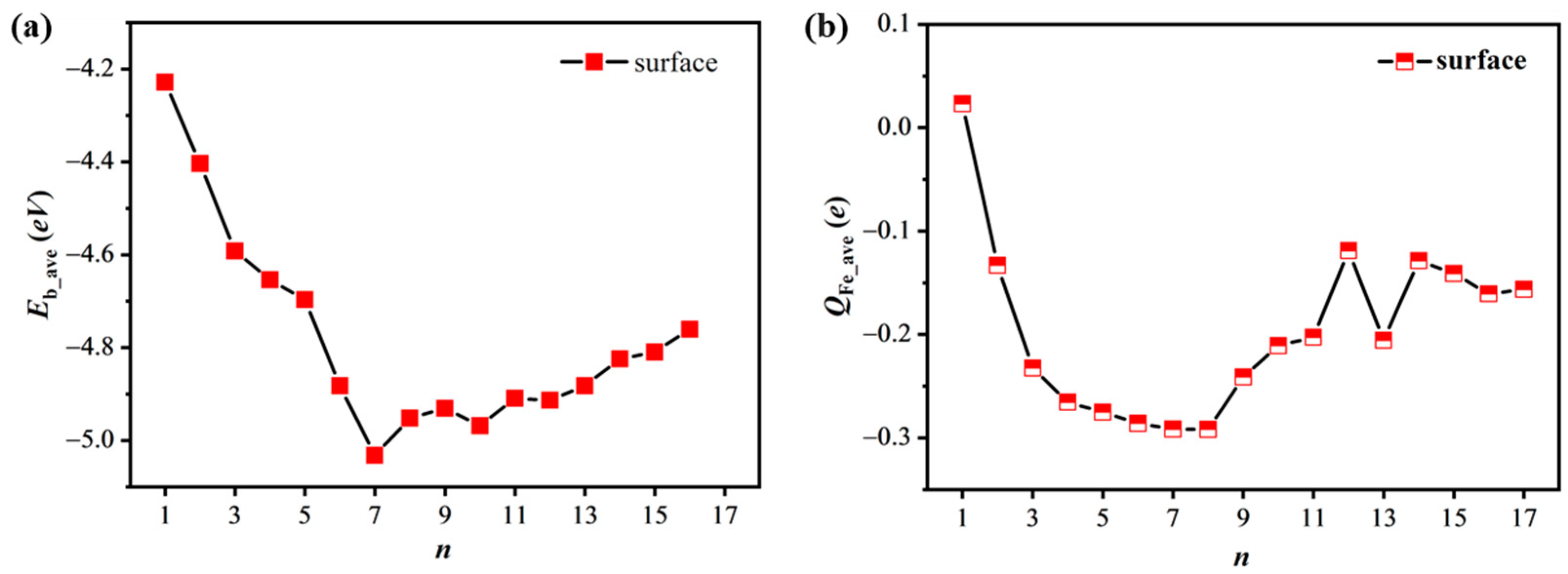
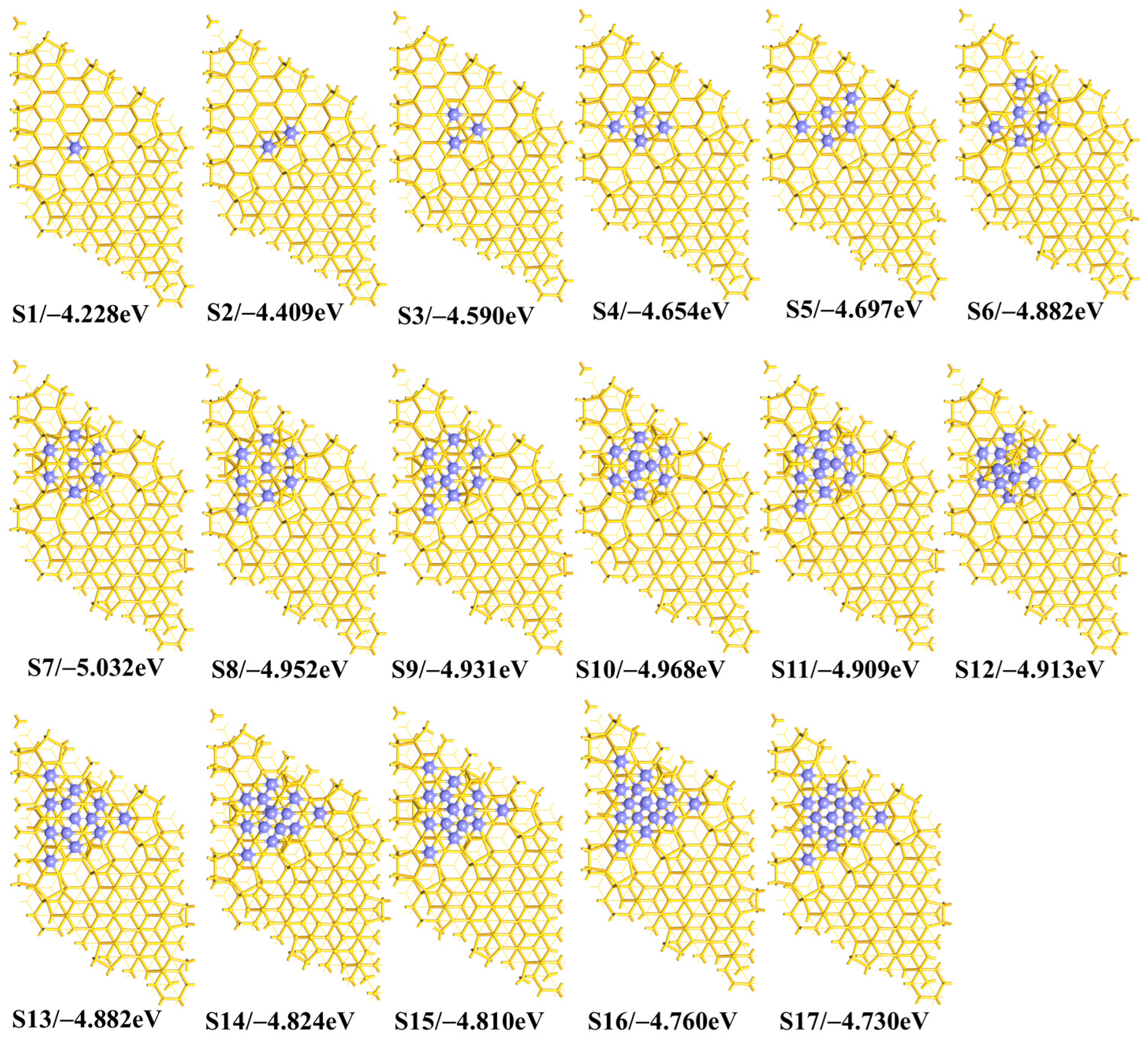
As the number
n is further increased, the
Eb_ave value becomes more negative until it reaches the minimum value of −5.032 eV when there are seven Fe atoms on the surface (
Scheme 2 S7), as shown in
Figure 1a and
Table S1 of the Supplementary Materials. The fourth and fifth Fe atoms are adsorbed at the
6d and
6g sites, respectively. The sixth and seventh Fe atoms are adsorbed at the
6e and
6s sites, respectively. We concluded that the Fe atoms prefer to stay at the six-membered ring sites close to each other on the surface. In this way, the seven Fe atoms form a wheel-like 7Fe geometry, with one Fe atom at the center and the other six atoms around the center. The presence of the wheel-like 7Fe geometry is related to the location of the first free Fe atoms, according to the energetically preferred path of these Fe atoms. Since the triangular pattern makes the system stable, as demonstrated theoretically by the case of coadsorption of three Fe atoms in the early part of this work, more triangular structures are generated by these seven Fe atoms through forming the wheel-like 7Fe geometry.
Compared to the
n = 7 case, the
Eb_ave value becomes less negative as the number
n increases. The eighth Fe atom is just beside the wheel (
Scheme 2 S8) but the ninth Fe atom is above the wheel (
Scheme 2 S9). When there are ten Fe atoms on the surface, the last three Fe atoms are all above the wheel (
Scheme 2 S10). As the number
n increases from 8 to 13, the
Eb_ave value presents a slight oscillation. In the
n = 13 case, all the six-membered ring sites are covered by Fe atoms, as is shown by
Scheme 2 S13. As the number
n increases from 13 to 17, the
Eb_ave value becomes less negative, because of the formation of fewer Fe–Si bonds but more Fe–Fe bonds. A general trend of the
Eb_ave ~
n variation thus is clear, that the
Eb_ave value first increases and then decreases, and reaches the minimum value at
n = 7, from which we conclude that the S7 model is more stable than the others in the case of Fe adsorption only on the surface.
Here, we wish to discuss the reason(s) for the trend of the
Eb_ave ~
n variation. In the case of a single Fe atom (
Scheme 2 S1), the Fe atom is positively charged by 0.023
e, which is consistent with common sense in that the Fe atom has slightly lower electronegativity than the silicon atom. In the cases of
n > 1, however, these
nFe atoms are negatively charged in the most stable geometries, because there are some Si atoms shared by these Fe atoms which limits the charge transfer from Fe to Si but facilitates the reversed charge transfer. The result is in agreement with the experimental result [
17] that the electronic binding energy of the Fe becomes smaller after the deposition of Fe on DASF. As shown in
Figure 1b, the average Bader charge (
QFe_ave) of Fe atoms becomes more negative from the cases
n = 1 (
Scheme 2 S1) to
n = 7 (
Scheme 2 S7) and then less negative as the number
n increases to 12. This trend of the
QFe_ave ~
n variation is very similar to that of the
Eb_ave ~
n variation. The charge transfer is strongest at
n = 7. In the
S7 case, the Bader charge of the central Fe atom is −0.387
e, which is much more negative than the
QFe_ave value of −0.276
e for the other six Fe atoms, because the central Fe atom is surrounded by fewer second-order neighboring Si atoms. However, the further increased Fe atoms interact weakly with the model. Note that the
QFe_ave value in the case of
n = 12 (
Scheme 2 S12) is less negative than in the cases of
n = 11 and
n = 13 (
Scheme 2 S11 and
S13), because there are more Fe–Fe bonds presented at
n = 12. These results suggest that what makes the wheel-like 7Fe geometry relatively stable is structurally due to the greater number of triangular structures formed by the Fe atoms than in the cases of
n < 7 and electronically due to the stronger charge transfer from Si to Fe atoms than the cases of
n > 7.
2.3. The Determining Factor(s) for Stabilizing the Wheel-like 7Fe Geometry
As is discussed above, the wheel-like 7Fe geometry has more triangular structures than other geometries generated by these seven Fe atoms. Next, it is important to study the stability of the minimum triangular structure at
n = 3 (
Scheme 2 S3) to understand the determining factor(s) for stabilizing the wheel-like 7Fe geometry.
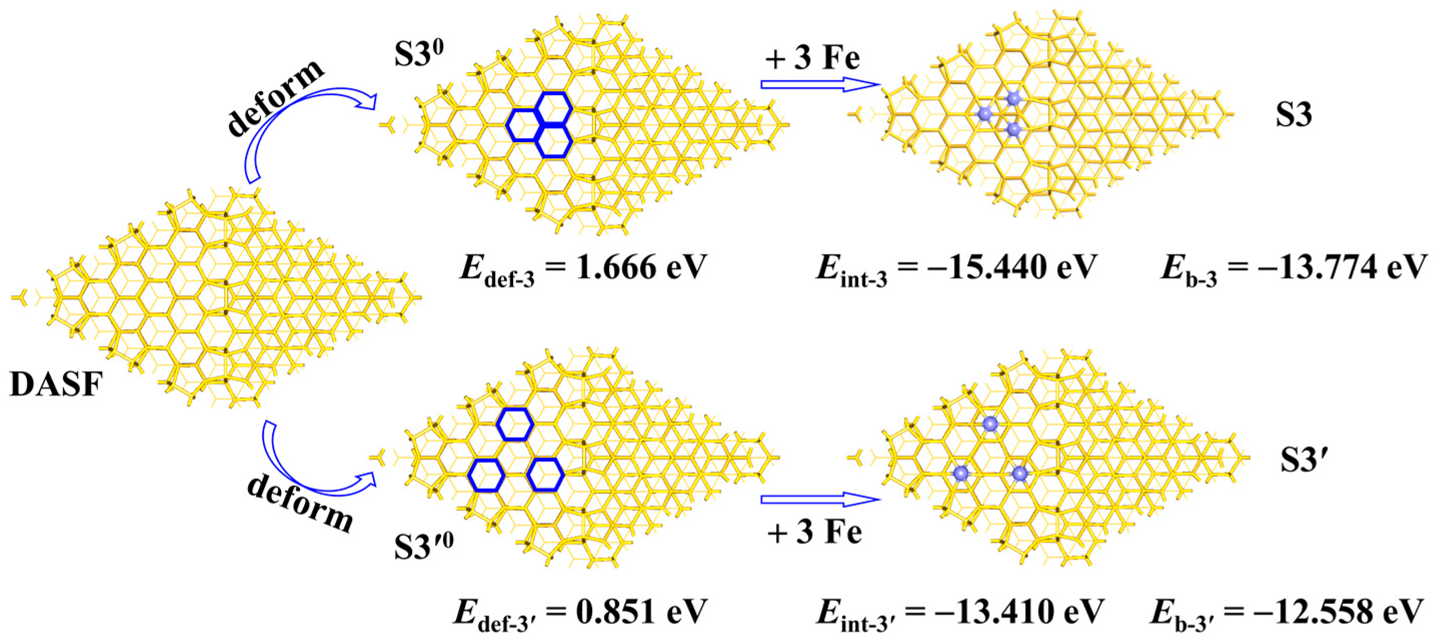
In
Scheme 3, we assumed a procedure to generate the
S3 structure and compared it with the formation process of the larger triangular structure
S3′. The
S3 structure is 1.216 eV more stable than the
S3′ structure, as indicated by the difference between the
Eb-3 and
Eb-3′ values. Similar methods are often used to investigate the interaction between two moieties in a system [
23,
24]. In the procedure to generate the
S3 structure, the DASF surface is first distorted to the structure
S30 taken to be same as that in
S3; the destabilization energy
Edef-3 in this step is defined by the equation
Edef-3 =
ES30 −
EDASF, where the subscript ‘‘def’’ means that the DASF geometry is deformed like that in the
S30 model;
ES30 is the total energy of the structure
S30; and
EDASF is the total energy of the DASF substrate. Lastly, three Fe atoms are added to the
S30 structure, affording the
S3 structure; in this step, the stabilization energy
Eint-3 is defined by the equation
Eint-3 =
ES3 − (
ES30 + 3
EFe), where
EFe is the total energy of the Fe atom. Obviously, the sum of
Edef-3 and
Eint-3 is equal to the value of the
Eb-3 value. Similarly, for the procedure to generate the
S3 structure, the DASF surface is first distorted to the structure
S3′0 taken to be same as that in
S3′. The destabilization energy
Edef-3′ in this step is defined by the equation
Edef-3′ =
ES3′0 −
EDASF, where the subscript ‘‘def’’ means that the DASF geometry is deformed like that in the
S3′0 model;
ES3′0 is the total energy of the structure
S3′0. Finally, three Fe atoms are added to the
S3′0 structure, with the formation of the
S3′ structure; in this step, the stabilization energy
Eint-3′ is defined by the equation
Eint-3′ =
ES3′ − (
ES3′0 + 3
EFe). The sum of
Edef-3′ and
Eint-3′ is equal to the value of the
Eb-3′ value.
The result shows that the Eint-3 value in the S3 case is considerably more negative by 2.030 eV than the Eint-3′ value in the S3′ case (−15.440 eV vs. −13.410 eV), meaning that the Fe-Si interaction is stronger in the S3 geometry than in the S3′ geometry. The QFe_ave value of the 3Fe atoms is −0.232 e in the S3 geometry but 0.024 e in the S3′ geometry, indicating that the charge transfer between the Fe and Si atoms is stronger in the S3 geometry than in the S3′ geometry, supporting the change in the Eint values. The Edef-3 value is much more positive by 0.81 eV than the Edef-3′ value (1.661 eV eV vs. 0.851 eV). This is reasonable because the large deformation is usually caused by the strong interaction. From the S3 case to the S3′ case, the decreased Edef value (0.81 eV) from the S30 geometry to the S3′0 geometry is much smaller than the increased Eint value (2.03 eV), showing that the Eint term plays a more important role in stabilizing the S3 geometry than does the S3′ geometry. It is indirectly proved that the system would become stable when the Fe atoms are clustered but without the presence of Fe–Fe bonds when the number of Fe atoms is not too large.
Therefore, the presence of a 7Fe wheel in the adsorption of Fe atoms is attributed to the enhanced Fe-Si interaction compared to the other geometries with the Fe atoms more dispersed.
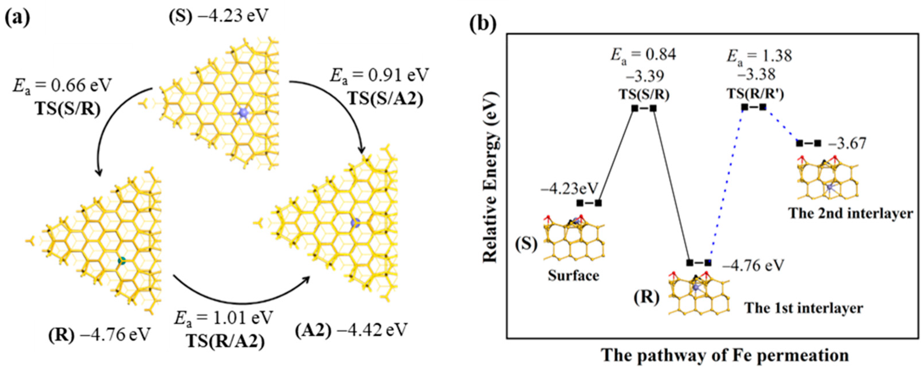
2.4. The Permeation of Fe Atoms into the Interlayer
The thermodynamic stability of Fe located in the interlayer is first compared. Below the Si
R and Si
A2 atoms are large enough spaces for Fe exitance, but with the binding energy of −4.76 eV and −4.42 eV, respectively. The difference between these two values is mainly resulting from the difference in the coordination environment that the Si
R atom is three-coordinated while the Si
A2 atom is four-coordinated. Thus, the Fe atom is energetically more stable just below the Si
R atom than below the Si
A2 atom. Then, the kinetic stability of Fe located in the interlayer is considered, as is shown in
Figure 2a. The activation barrier (
Ea) of the
S→
R step is 0.66 eV for the Fe atom on the surface permeating to position
R just below the Si
R atom through the transition state
TS(S/R), which is smaller than the 0.91 eV of the
S→
A2 step for the Fe atom on the surface permeating to position
A2 just below the Si
A2 atom through
TS(S/A2), indicating that the surface Fe atom shifts to position
R more easily than to position
A2. The
Ea value of the
R→
A2 step is 1.01 eV for the Fe atom just below the Si
R atom moving to position
A2 through
TS(R/A2); this step is endothermic by 0.32 eV. Since the total energy of
TS(R/A2) is 0.43 eV lower than that of
TS(S/A2), the surface Fe kinetically prefers to move first to position
R and then to position
A2 (
S→
R→
A2) rather than directly to position
A2 (
R→
A2). Thermodynamically, the Fe atom at position
R is more stable than at position
A2. As is shown in
Figure 2b, further permeation into the deep layer is difficult due to the large
Ea value of 1.38 eV and endothermicity of 1.09 eV, so the thickness for Fe deposition is about 0.6 nm. These results suggested that the Fe atom at position
R is thermodynamically and kinetically stable. Next, we expanded the discussion to the location of Fe atoms permeating freely into the first interlayer.
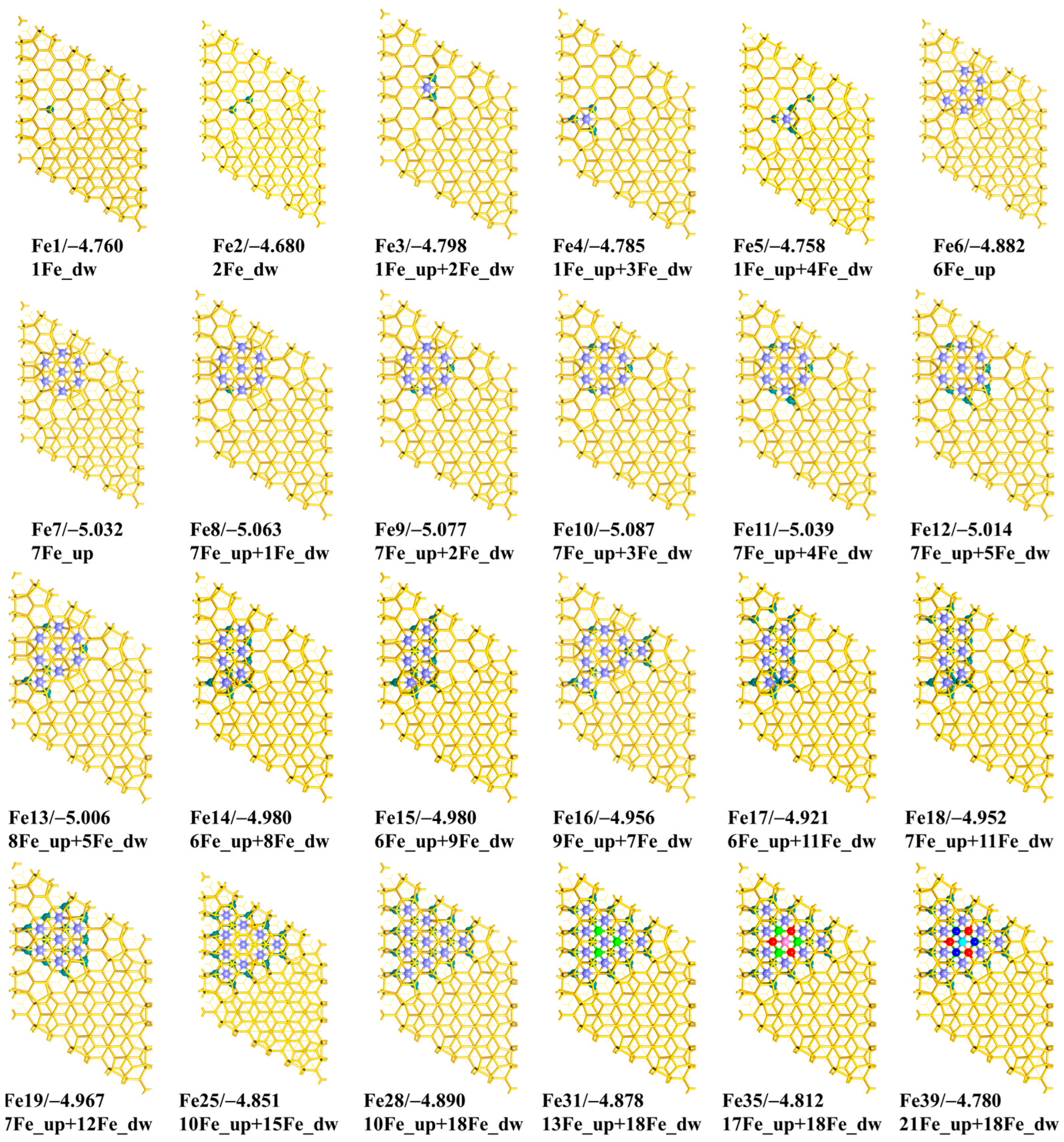
As is shown in
Scheme 4, the most stable structures of
nFe deposition are found with
x Fe atoms deposited to the upmost surface (represented by
xFe_up) and
y Fe atoms permeating into the first interlayer (represented by
yFe_dw) (
n =
x +
y). When
n = 2, the most stable geometry has one Fe atom at position
R and the other Fe atom at position
A2 (
Scheme 4 Fe1 and
Fe2). Because a single Fe atom is the most stable at one of the R positions, we thus checked the other
R positions for the second Fe atom when the first Fe atom does not move but found that the
Eb_ave value in this case will decrease slightly (by 0.01 eV). When
n = 3, 4, and 5 (
Scheme 4 Fe3,
Fe4, and
Fe5, respectively), there is only one Fe atom adsorbed on the six-membered ring. When
n = 6 and 7 (
Scheme 4 Fe6 and
Fe7), all the Fe atoms are adsorbed on the surface. In particular, the most stable geometry at
n = 7 (
Scheme 4 Fe7) is the same as the wheel 7Fe geometry above (
Scheme 2 S7), even when the Fe atoms are considered to penetrate freely from the surface into the interlayer. In the cases from
n = 7 to
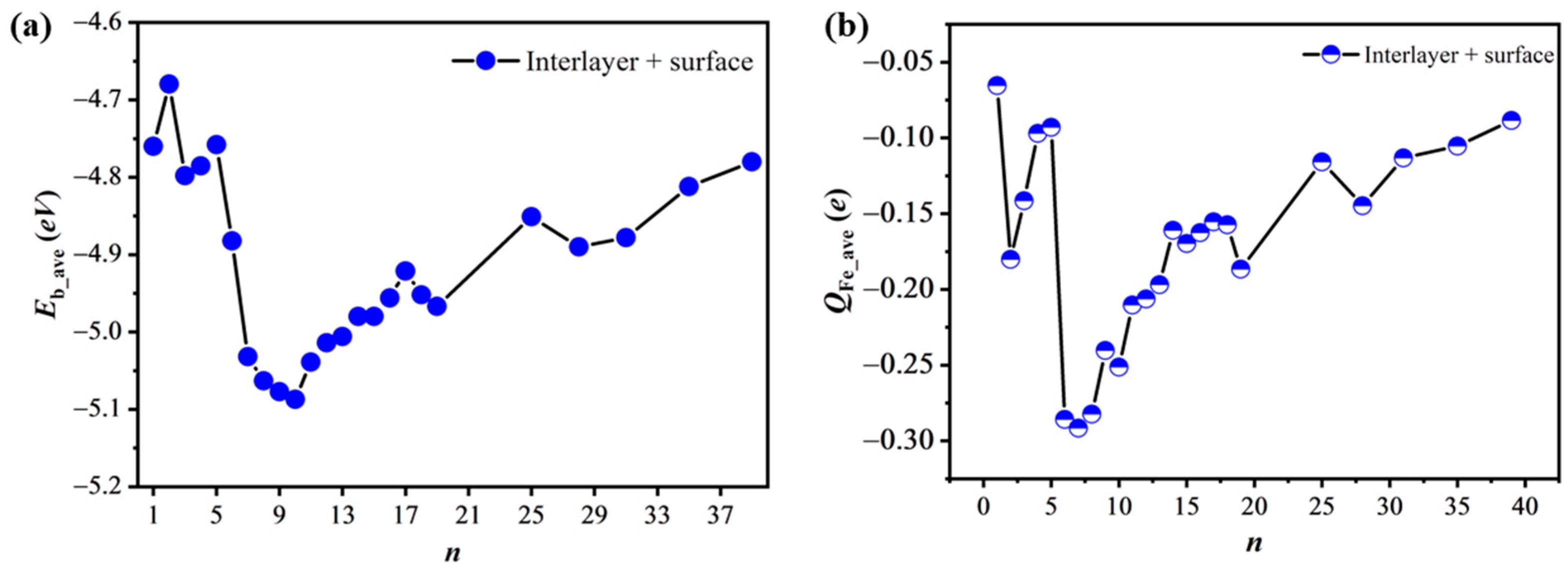
n = 13, the most stable geometry still appears to be the wheel 7Fe structure. As shown in
Figure 3a and
Table S2 of the Supplementary Materials, the
Eb_ave value first becomes more negative and then less negative, and reaches the minimum −5.09 eV at
n = 10 (
Scheme 4 Fe10). Until the number
n increases to 28 (
Scheme 4 Fe28), all the positions in the interlayer are occupied by 18 Fe atoms and all the positions on the six-membered rings are adsorbed by the remaining 10 Fe atoms. To further increase the
n value, the
Eb_ave value become much smaller than at
n = 28, due to the formation of Fe–Fe bonds, as shown by the
Fe31,
Fe35, and
Fe39 models in
Scheme 4. These results show that the
Fe10 model is more stable than the others in the case that the Fe atom permeates freely from the surface to the interlayer.
Although we have obtained the geometries of nFe/DASF with the most negative Eb_ave values, there are limitations in a real experiment at finite temperatures. The influence of the entropy effect and phononic contributions to the free energy, which we have not considered in this work, might change the relative stabilities of geometries with and without Fe permeation, because the differences in Eb_ave values between two models are not very large. For example, the difference in the Eb_ave values between the Fe7 and Fe10 models is just 0.055 eV. When considering such an influence, these energy differences will become smaller and the relative stability of them might be altered. Therefore, it is difficult to conclude which phase(s) would occur or coexist in a real situation at finite temperatures, and it is not clear whether Fe diffuses into the surface or not with the present approach.
In the case of Fe permeation, the
Eb_ave ~
n variation is generally similar to the trend of the
QFe_ave ~
n variation (
Figure 3b), suggesting that the bonding interaction is the main determining factor for the trends. The
QFe_ave value of two Fe atoms (
Scheme 4 Fe2) is −0.18
e, which is 0.11
e more negative than the −0.07
e for the single Fe atom (
Scheme 4 Fe1). The spin densities of the two Fe atoms are 1.58
μB and −0.69
μB, which are much smaller than the 1.74
μB for the single Fe atom, suggesting that the spin-pairing interaction between the Fe and Si atoms is stronger in
Fe2 than in
Fe1. From
n = 3 to
n = 17, the
QFe_ave value first becomes more negative and then less negative with the minimum value presented at
n = 7, as shown in
Figure 3b. Although the
Eb_ave value at
n = 10 (
Scheme 4 Fe10) is 0.055 eV more negative than that at
n = 7 (
Scheme 4 Fe7), the
QFe_ave value is 0.04
e less negative at
n = 10 than that at
n = 7. The average spin density at
n = 10 is 0.06
μB, which is smaller than the 0.15
μB at
n = 7, indicating that the spin-pairing interaction between the Fe atoms and Si atoms is stronger at
n =10 than at
n = 7. In the
Fe10 model, the Bader charge of the central Fe of the “7Fe wheel” is −0.348
e; the
QFe_ave value of the six Fe atoms along the ring of the “7Fe wheel” is −0.288
e and that of the three Fe atoms below the “7Fe wheel” is −0.145
e. In the cases from the
S7 model (
Scheme 2) to the
Fe10 model (
Scheme 4), the Bader charge of the central Fe of the “7Fe wheel” becomes less negative by 0.039
e while the
QFe_ave value for the six Fe atoms along the ring of the “7Fe wheel” becomes more negative by 0.012
e. From these results, it can be predicted that the reactivities of the two models are similar, as we will discuss below, because these differences are not very large.
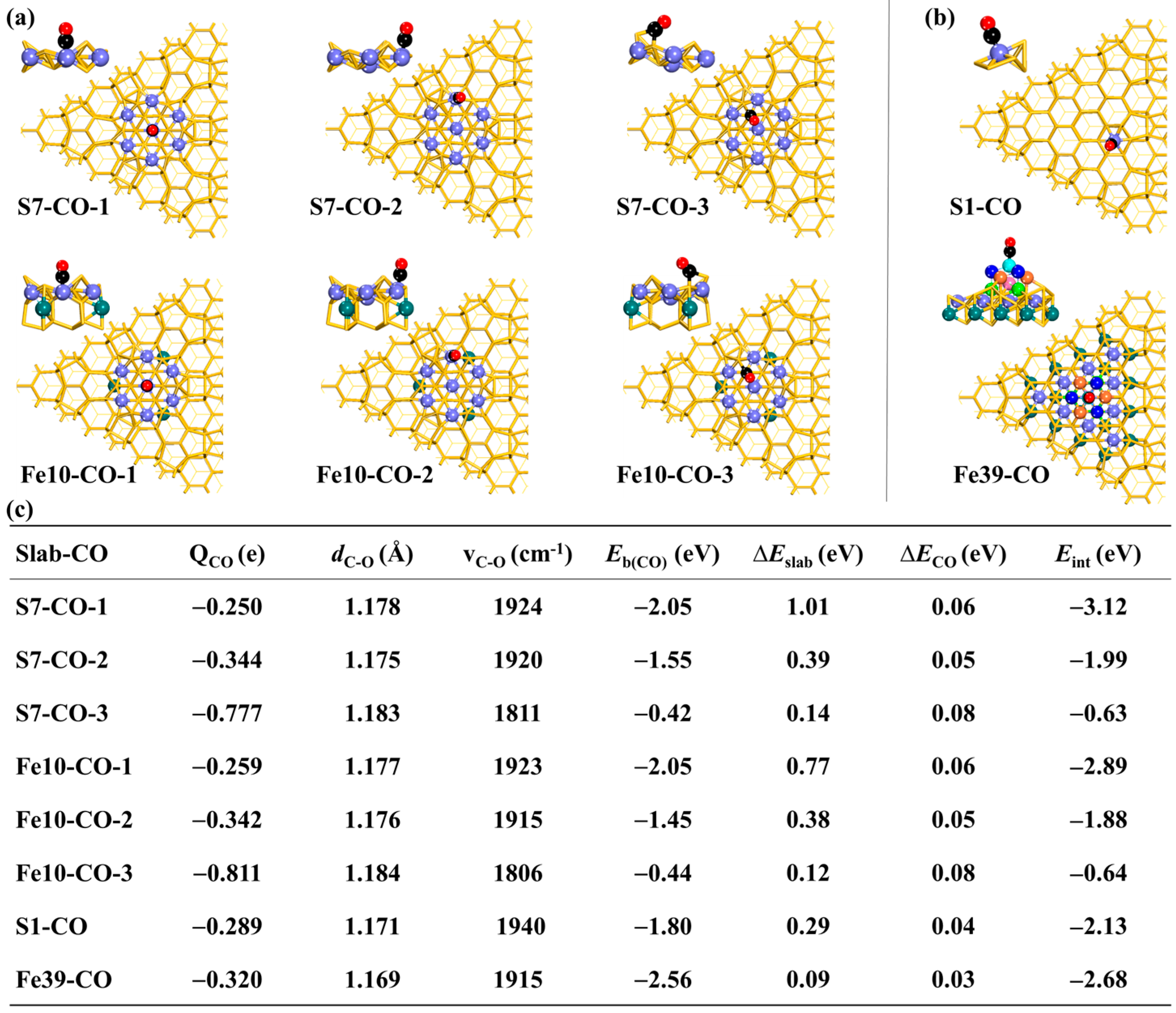
2.5. CO Adsorption
The surface reactivity of
nFe/DASF is explored taking CO adsorption to them as an example, because CO adsorption is often studied to evaluate the surface reactivity of many materials. Koo et al. [
25] carried out experiments and theoretical calculations about CO adsorption on the DASF without Fe atoms, and reported that the adsorption of CO molecules occurs on the Si
A atoms. However, the interaction of CO with the Fe atoms on the DASF surface remains unclear. We studied the adsorption of CO on the models of
S7 in
Scheme 2 and
Fe10 in
Scheme 4, because they are more stable than other geometries. As shown in
Scheme 5, the geometries and energies of the CO adsorption on the
S7 and
Fe10 models are parallel to those of the CO adsorption on the
S1 and
Fe39 models for easy comparison. Generally, the CO adsorption at the central Fe site of both the
S7 and
Fe10 models is stronger than in the
S1 model, but is weaker than in the
Fe39 model where CO does not interact with Si atoms, suggesting that the CO adsorption in the
nFe/DASF model is greatly influenced by the surrounding Si atoms. The influence of Si atoms on CO adsorption is discussed in detail below.
In the
S7 case, the CO molecule binds to the central Fe site of the “7Fe wheel”, according to the
S7-CO-1 geometry, with a binding energy (
Eb(CO)) of −2.05 eV. The CO adsorption becomes weak when it binds with the Fe atom along the ring of the “7Fe wheel”, as is shown by the
S7-CO-2 geometry with an
Eb(CO) value of −1.55 eV. Compared with
S7-CO-1 and
S7-CO-2, the CO adsorption in
S7-CO-3 is much weaker. There is a C–Fe bond but no C–Si bond formed in
S7-CO-1 and
S7-CO-2, whereas
S7-CO-3 has a C–Si bond but no C–Fe bond. In
S7-CO-3, the C atom of CO binds to two Si atoms, where the C–Si distances are 1.917 Å (with the adatom Si) and 2.224 Å (with the other Si), very close to the result by Shong et al. [
26]. In the cases from
S7-CO-1 to
S7-CO-3, the C–O distance (
dC-O) lengthens moderately from 1.178 Å to 1.183 Å and the C−O stretching frequency (
vCO) decreases from 1924 cm
−1 to 1811 cm
−1. Therefore, the CO molecule prefers the Fe atom to the Si atom in the
S7 model.
When going from
S7-CO-1 to
S7-CO-2 and to
S7-CO-3, the deformation energy of the CO (∆
ECO) changes little; however, the deformation energy of the model (∆
Eslab) decreases greatly. The interaction energy (
Eint) between the model and the CO molecule becomes less negative from −3.12 eV to −1.99 eV and to −0.63 eV, suggesting that the charge transfer between the model and the CO molecule is expected to be weaker in the order of
S7-CO-1 >
S7-CO-2 >
S7-CO-3. The Bader charge (
QCO) of CO is negative and becomes more negative from −0.250
e in
S7-CO-1 to −0.344
e in
S7-CO-2 and to −0.777
e in
S7-CO-3, which is because the central Fe atom compared to the other Fe atoms is much more negatively charged (as is discussed in
Section 2.1) and its
d orbitals thus are occupied by more electrons than the other Fe atoms, suppressing its ability to accept electrons but promoting its ability to donate electrons. The charge of −0.777
e for CO in
S7-CO-3 is mainly contributed by the charge transfer from the Si atom to the CO molecule.
The CO adsorption on the Fe10 model is very similar to the S7 model, whether from the aspect of the Eb(CO) term or from the aspects of the QCO, dC-O, and vCO terms. The result shows that the adsorption of CO is little influenced by the permeation of three additional Fe atoms into the interlay, which is reasonable because each of the Fe atoms shares only one Si atom with the central Fe atom of the “7Fe wheel” and no Fe–Fe bond is formed between them. The ∆ECO values are very similar for both models but the Fe10 model deforms less than the S7 model, which is consistent with the more negative Eb_ave value in the Fe10 model than in the S7 model (−5.087 eV vs. −5.032 eV), as well as the distribution of the electron density in these two models.


 ,
, 


