


Concerns on the Effects of Electrode Positions in Electrolyte Container for the Oxygen Evolution Reaction

Abstract
:1. Introduction
2. Results and Discussion
3. Materials and Methods
3.1. Materials
3.2. Electrochemical Characterizations
4. Conclusions
Author Contributions
Funding
Institutional Review Board Statement
Informed Consent Statement
Data Availability Statement
Conflicts of Interest
References
- Hassan, Q.; Sameen, A.Z.; Salman, H.M.; Jaszczur, M.; Al-Jiboory, A.K. Hydrogen energy future: Advancements in storage technologies and implications for sustainability. J. Energy Storage 2023, 72, 108404. [Google Scholar] [CrossRef]
- Megía, P.J.; Vizcaíno, A.J.; Calles, J.A.; Carrero, A. Hydrogen Production Technologies: From Fossil Fuels toward Renewable Sources. A Mini Review. Energy Fuels 2021, 35, 16403–16415. [Google Scholar] [CrossRef]
- Wang, Y.; Vogel, A.; Sachs, M.; Sprick, R.S.; Wilbraham, L.; Moniz, S.J.A.; Godin, R.; Zwijnenburg, M.A.; Durrant, J.R.; Cooper, A.I.; et al. Current understanding and challenges of solar-driven hydrogen generation using polymeric photocatalysts. Nat. Energy 2019, 4, 746–760. [Google Scholar] [CrossRef]
- Zhu, J.; Hu, L.; Zhao, P.; Lee, L.Y.S.; Wong, K.-Y. Recent Advances in Electrocatalytic Hydrogen Evolution Using Nanoparticles. Chem. Rev. 2020, 120, 851–918. [Google Scholar] [CrossRef] [PubMed]
- Terlouw, T.; Bauer, C.; McKenna, R.; Mazzotti, M. Large-scale hydrogen production via water electrolysis: A techno-economic and environmental assessment. Energy Environ. Sci. 2022, 15, 3583–3602. [Google Scholar] [CrossRef]
- Kibsgaard, J.; Chorkendorff, I. Considerations for the scaling-up of water splitting catalysts. Nat. Energy 2019, 4, 430–433. [Google Scholar] [CrossRef]
- Song, J.; Wei, C.; Huang, Z.-F.; Liu, C.; Zeng, L.; Wang, X.; Xu, Z.J. A review on fundamentals for designing oxygen evolution electrocatalysts. Chem. Soc. Rev. 2020, 49, 2196–2214. [Google Scholar] [CrossRef] [PubMed]
- Li, H.; Pan, Y.; Wu, L.; He, R.; Qin, Z.; Luo, S.; Yang, L.; Zeng, J. IrO2 deposited on RuO2 as core-shell structured RuO2@IrO2 for oxygen evolution reaction in electrochemical water electrolyzer. Mol. Catal. 2023, 551, 113619. [Google Scholar] [CrossRef]
- Wu, Z.-Y.; Chen, F.-Y.; Li, B.; Yu, S.-W.; Finfrock, Y.Z.; Meira, D.M.; Yan, Q.-Q.; Zhu, P.; Chen, M.-X.; Song, T.-W.; et al. Non-iridium-based electrocatalyst for durable acidic oxygen evolution reaction in proton exchange membrane water electrolysis. Nat. Mater. 2023, 22, 100–108. [Google Scholar] [CrossRef]
- Qin, Y.; Yu, T.; Deng, S.; Zhou, X.-Y.; Lin, D.; Zhang, Q.; Jin, Z.; Zhang, D.; He, Y.-B.; Qiu, H.-J.; et al. RuO2 electronic structure and lattice strain dual engineering for enhanced acidic oxygen evolution reaction performance. Nat. Commun. 2022, 13, 3784. [Google Scholar] [CrossRef]
- Mamaca, N.; Mayousse, E.; Arrii-Clacens, S.; Napporn, T.W.; Servat, K.; Guillet, N.; Kokoh, K.B. Electrochemical activity of ruthenium and iridium based catalysts for oxygen evolution reaction. Appl. Catal. B Environ. 2012, 111–112, 376–380. [Google Scholar] [CrossRef]
- Yang, L.; Liu, Z.; Zhu, S.; Feng, L.; Xing, W. Ni-based layered double hydroxide catalysts for oxygen evolution reaction. Mater. Today Phys. 2021, 16, 100292. [Google Scholar] [CrossRef]
- Khan, N.A.; Rashid, N.; Junaid, M.; Zafar, M.N.; Faheem, M.; Ahmad, I. NiO/NiS Heterostructures: An Efficient and Stable Electrocatalyst for Oxygen Evolution Reaction. ACS Appl. Energy Mater. 2019, 2, 3587–3594. [Google Scholar] [CrossRef]
- He, D.; Song, X.; Li, W.; Tang, C.; Liu, J.; Ke, Z.; Jiang, C.; Xiao, X. Active Electron Density Modulation of Co3O4-Based Catalysts Enhances their Oxygen Evolution Performance. Angew. Chem. Int. Ed. 2020, 59, 6929–6935. [Google Scholar] [CrossRef] [PubMed]
- Li, S.; Hao, X.; Abudula, A.; Guan, G. Nanostructured Co-based bifunctional electrocatalysts for energy conversion and storage: Current status and perspectives. J. Mater. Chem. A 2019, 7, 18674–18707. [Google Scholar] [CrossRef]
- Xu, X.; Su, C.; Shao, Z. Fundamental Understanding and Application of Ba0.5Sr0.5Co0.8Fe0.2O3−δ Perovskite in Energy Storage and Conversion: Past, Present, and Future. Energy Fuels 2021, 35, 13585–13609. [Google Scholar] [CrossRef]
- Xu, X.; Wang, W.; Zhou, W.; Shao, Z. Recent Advances in Novel Nanostructuring Methods of Perovskite Electrocatalysts for Energy-Related Applications. Small Methods 2018, 2, 1800071. [Google Scholar] [CrossRef]
- Nong, H.N.; Falling, L.J.; Bergmann, A.; Klingenhof, M.; Tran, H.P.; Spöri, C.; Mom, R.; Timoshenko, J.; Zichittella, G.; Knop-Gericke, A.; et al. Key role of chemistry versus bias in electrocatalytic oxygen evolution. Nature 2020, 587, 408–413. [Google Scholar] [CrossRef]
- Kang, W.; Wei, R.; Yin, H.; Li, D.; Chen, Z.; Huang, Q.; Zhang, P.; Jing, H.; Wang, X.; Li, C. Unraveling Sequential Oxidation Kinetics and Determining Roles of Multi-Cobalt Active Sites on Co3O4 Catalyst for Water Oxidation. J. Am. Chem. Soc. 2023, 145, 3470–3477. [Google Scholar] [CrossRef]
- Huang, Z.-F.; Song, J.; Du, Y.; Xi, S.; Dou, S.; Nsanzimana, J.M.V.; Wang, C.; Xu, Z.J.; Wang, X. Chemical and structural origin of lattice oxygen oxidation in Co–Zn oxyhydroxide oxygen evolution electrocatalysts. Nat. Energy 2019, 4, 329–338. [Google Scholar] [CrossRef]
- Righi, G.; Plescher, J.; Schmidt, F.-P.; Campen, R.K.; Fabris, S.; Knop-Gericke, A.; Schlögl, R.; Jones, T.E.; Teschner, D.; Piccinin, S. On the origin of multihole oxygen evolution in haematite photoanodes. Nat. Catal. 2022, 5, 888–899. [Google Scholar] [CrossRef]
- Haase, F.T.; Bergmann, A.; Jones, T.E.; Timoshenko, J.; Herzog, A.; Jeon, H.S.; Rettenmaier, C.; Cuenya, B.R. Size effects and active state formation of cobalt oxide nanoparticles during the oxygen evolution reaction. Nat. Energy 2022, 7, 765–773. [Google Scholar] [CrossRef]
- Wang, X.; Xi, S.; Huang, P.; Du, Y.; Zhong, H.; Wang, Q.; Borgna, A.; Zhang, Y.-W.; Wang, Z.; Wang, H.; et al. Pivotal role of reversible NiO6 geometric conversion in oxygen evolution. Nature 2022, 611, 702–708. [Google Scholar] [CrossRef] [PubMed]
- Jia, H.; Yao, N.; Yu, C.; Cong, H.; Luo, W. Unveiling the Electrolyte Cations Dependent Kinetics on CoOOH-Catalyzed Oxygen Evolution Reaction. Angew. Chem. Int. Ed. 2023, 62, e202313886. [Google Scholar] [CrossRef] [PubMed]
- Zhao, K.; Tao, Y.; Fu, L.; Li, C.; Xu, B. Bifunctional Near-Neutral Electrolyte Enhances Oxygen Evolution Reaction. Angew. Chem. Int. Ed. 2023, 62, e202308335. [Google Scholar] [CrossRef]
- Liang, Q.; Brocks, G.; Bieberle-Hütter, A. Oxygen evolution reaction (OER) mechanism under alkaline and acidic conditions. J. Phys. Energy 2021, 3, 026001. [Google Scholar] [CrossRef]
- Tang, J.; Xu, X.; Tang, T.; Zhong, Y.; Shao, Z. Perovskite-Based Electrocatalysts for Cost-Effective Ultrahigh-Current-Density Water Splitting in Anion Exchange Membrane Electrolyzer Cell. Small Methods 2022, 6, 2201099. [Google Scholar] [CrossRef]
- Stevens, M.B.; Enman, L.J.; Batchellor, A.S.; Cosby, M.R.; Vise, A.E.; Trang, C.D.M.; Boettcher, S.W. Measurement Techniques for the Study of Thin Film Heterogeneous Water Oxidation Electrocatalysts. Chem. Mater. 2017, 29, 120–140. [Google Scholar] [CrossRef]
- Bard, A.J.; Faulkner, L.R. Electrochemical Methods: Fundamentals and Applications, 2nd ed.; John Wiley & Sons: New York, NY, USA, 2001. [Google Scholar]
- Zhang, W.; Chen, X.; Wang, Y.; Wu, L.; Hu, Y. Experimental and Modeling of Conductivity for Electrolyte Solution Systems. ACS Omega 2020, 5, 22465–22474. [Google Scholar] [CrossRef]
- Pérez-Herranz, V.; Guiñón, J.L.; García-Antón, J. A new technique for the visualization of the concentration boundary layer in an electrodialysis cell. J. Appl. Electrochem. 2000, 30, 809–816. [Google Scholar] [CrossRef]
- Zhou, Y. Materials Engineering Fundamentals, 1st ed.; Wuhan University of Technology Press: Wuhan, China, 2011. [Google Scholar]
- Zhu, M.; Yu, Q. Thermal Engineering Fundamentals, 1st ed.; Wuhan University of Technology Press: Wuhan, China, 2014. [Google Scholar]
- Wu, B.; Gong, S.; Lin, Y.; Li, T.; Chen, A.; Zhao, M.; Zhang, Q.; Chen, L. A Unique NiOOH@FeOOH Heteroarchitecture for Enhanced Oxygen Evolution in Saline Water. Adv. Mater. 2022, 34, 2108619. [Google Scholar] [CrossRef] [PubMed]
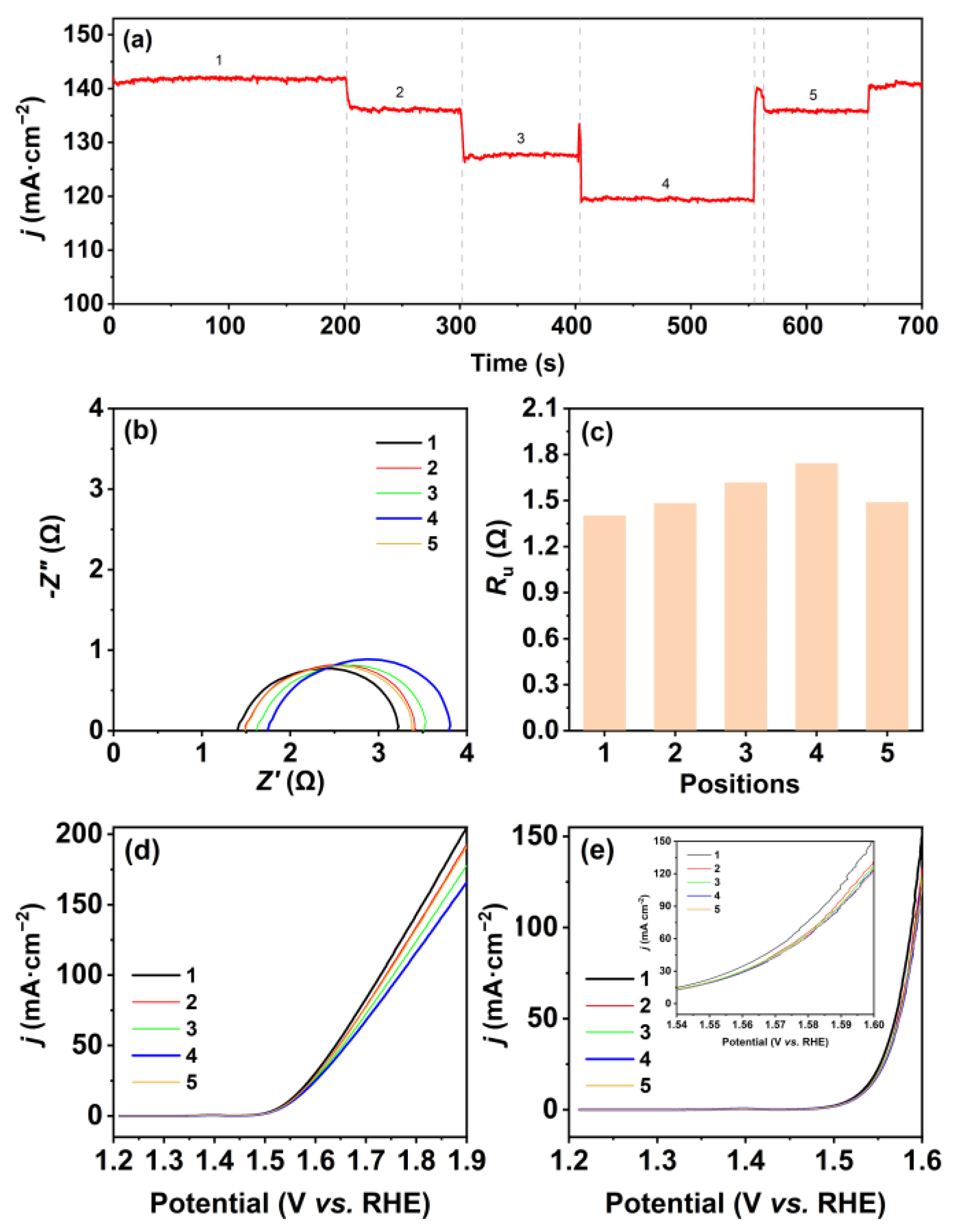
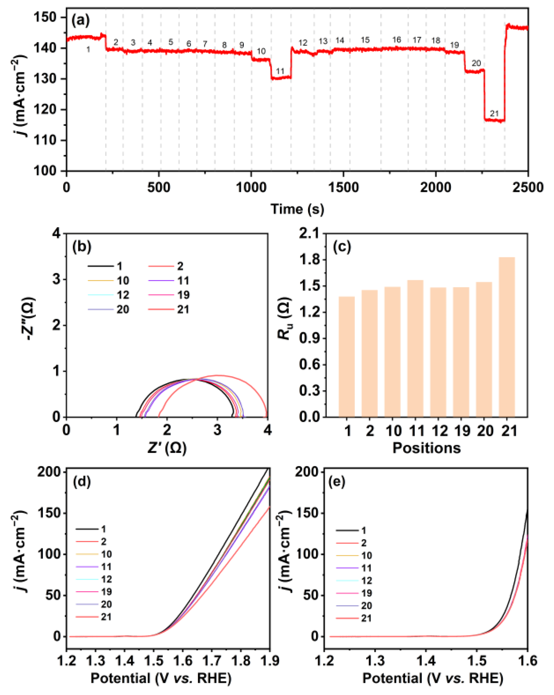
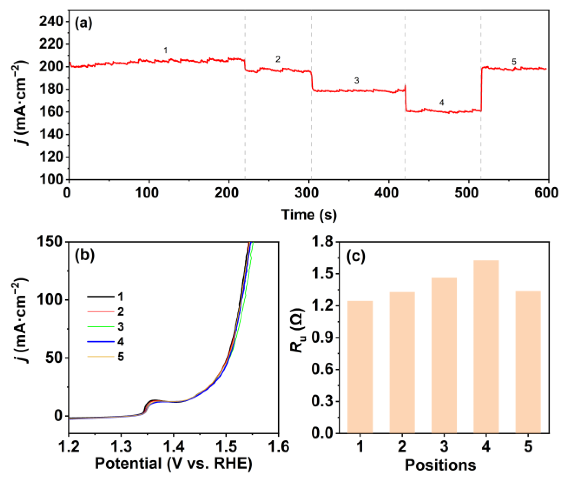
 : the three-electrode system).
: the three-electrode system).
: the three-electrode system).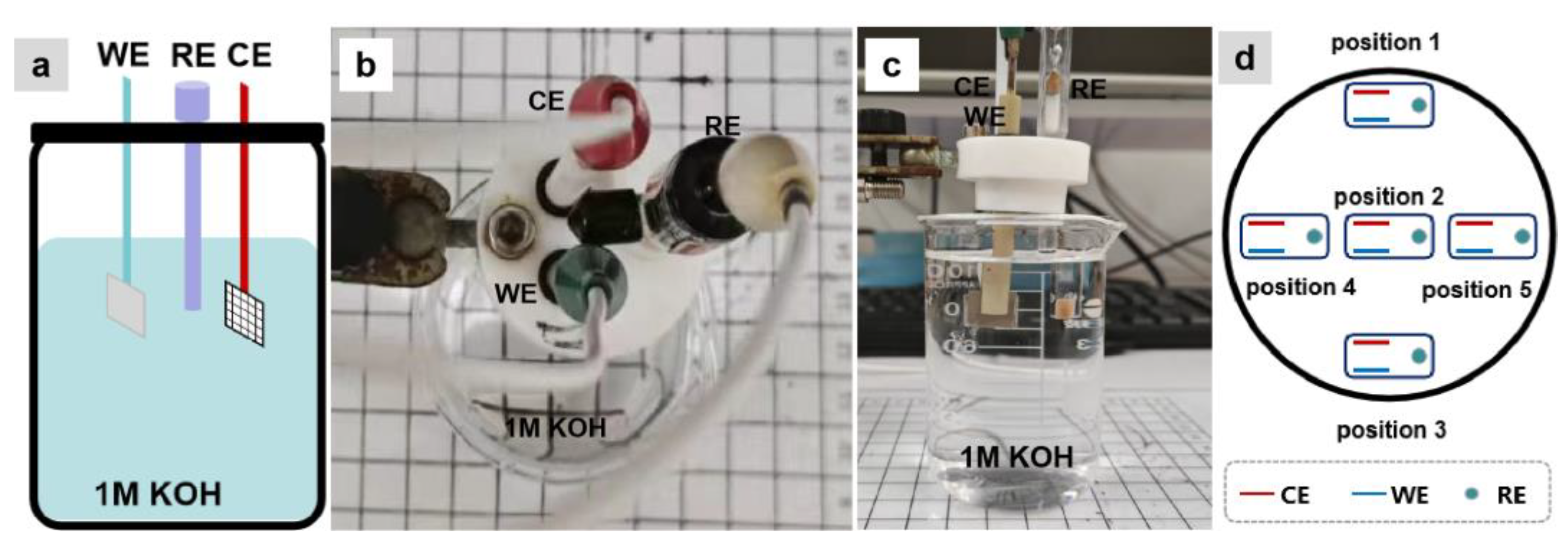
 : the three-electrode system).
: the three-electrode system).
: the three-electrode system).
Disclaimer/Publisher’s Note: The statements, opinions and data contained in all publications are solely those of the individual author(s) and contributor(s) and not of MDPI and/or the editor(s). MDPI and/or the editor(s) disclaim responsibility for any injury to people or property resulting from any ideas, methods, instructions or products referred to in the content. |
© 2023 by the authors. Licensee MDPI, Basel, Switzerland. This article is an open access article distributed under the terms and conditions of the Creative Commons Attribution (CC BY) license (https://creativecommons.org/licenses/by/4.0/).
Share and Cite
Zhang, F.; Zhao, Y.; Chen, X.; Zhao, S.; Zhou, J.; Lu, Z.; Lin, Y. Concerns on the Effects of Electrode Positions in Electrolyte Container for the Oxygen Evolution Reaction. Molecules 2023, 28, 8143. https://doi.org/10.3390/molecules28248143
Zhang F, Zhao Y, Chen X, Zhao S, Zhou J, Lu Z, Lin Y. Concerns on the Effects of Electrode Positions in Electrolyte Container for the Oxygen Evolution Reaction. Molecules. 2023; 28(24):8143. https://doi.org/10.3390/molecules28248143
Chicago/Turabian StyleZhang, Fan, Yayun Zhao, Xiaofeng Chen, Shengxiao Zhao, Junjie Zhou, Zhiyi Lu, and Yichao Lin. 2023. "Concerns on the Effects of Electrode Positions in Electrolyte Container for the Oxygen Evolution Reaction" Molecules 28, no. 24: 8143. https://doi.org/10.3390/molecules28248143
APA StyleZhang, F., Zhao, Y., Chen, X., Zhao, S., Zhou, J., Lu, Z., & Lin, Y. (2023). Concerns on the Effects of Electrode Positions in Electrolyte Container for the Oxygen Evolution Reaction. Molecules, 28(24), 8143. https://doi.org/10.3390/molecules28248143