Communication

Concerns on the Effects of Electrode Positions in Electrolyte Container for the Oxygen Evolution Reaction

1
Renewable Energy Engineering Institute, Power China Huadong Engineering Corporation Limited, Hangzhou 311122, China
2
Key Laboratory of Advanced Fuel Cells and Electrolyzers Technology of Zhejiang Province, Ningbo Institute of Materials Technology and Engineering, Chinese Academy of Sciences, Ningbo 315201, China
3
Key Laboratory of Far-Shore Wind Power Technology of Zhejiang Province, Hangzhou 311122, China
4
University of Chinese Academy of Sciences, Beijing 100049, China
*
Authors to whom correspondence should be addressed.
Molecules 2023, 28(24), 8143; https://doi.org/10.3390/molecules28248143
Submission received: 11 November 2023 / Revised: 29 November 2023 / Accepted: 7 December 2023 / Published: 18 December 2023

Abstract

:
Water electrolysis is currently a major technique to produce clean hydrogen, which is regarded as a promising and sustainable energy carrier. The efficiency of water electrolysis is highly dependent on the oxygen evolution reaction (OER) on the anode. The evaluation of an OER electrocatalyst is frequently carried out on a three-electrode system in a container of electrolyte. Herein, we found that the electrode positions in the electrolyte container could significantly affect the data acquisition of OER performance. After a detailed investigation, we reveal that the difference of the OER activity of an electrocatalyst at a different position is originated from their different iRu drop and the gas diffusion resistance. For the first time, this work evokes concerns on the accurate evaluation of electrocatalysts regarding the electrode position. For fair comparisons and reliable results, it is strongly suggested to keep the electrode position unchanged in the electrochemical measurements. In addition, the establishment of a standard electrolyzer setup for electrocatalysis evaluation in the electrochemical community is also called for.

1. Introduction

Hydrogen, as a sustainable energy carrier, possesses broad and abundant resources and high energy density and is not constrained by geographical limitations, thus distinguishing it from other renewable energy technologies such as tidal, solar, and wind energy [1,2]. Furthermore, the combustion of hydrogen only generates water as a byproduct, thereby not only addressing energy-related concerns but also mitigating environmental issues associated with conventional fossil fuels [3,4]. Within the hydrogen energy technology chain, hydrogen production plays a pivotal role and water electrolysis exhibits the potential for large-scale hydrogen generation while also enabling coupling with other forms of renewable energy for hydrogen–electric cycles [5]. Water electrolysis produces hydrogen on the cathode, while its efficiency is highly dependent on the oxygen evolution reaction (OER) on the anode. Currently, the sluggish kinetics of electrochemical OER hampers the widespread application of water electrolysis technology [6,7]. To date, substantial studies have been devoted to exploring efficient OER electrocatalysts, focusing on the subsequent three areas: (1) the design and optimization of catalysts with high OER efficiency, which play a crucial role in the OER reaction, including the exceptionally superior noble-metal-based metallic catalysts (such as IrO2 and RuO2) and some materials with unique electronic structures and chemical properties, such as cobalt-based and nickel-based catalysts, and so on [8,9,10,11,12,13,14,15,16,17]; (2) in-depth study of OER mechanisms and the detailed processes, including the formation and transformation of intermediates, as well as the reaction pathways and rate-determining steps, which have been revealed by utilizing advanced experimental techniques and theoretical calculations, thereby providing important theoretical foundations for guiding the design and optimization of catalysts [18,19,20,21,22,23]; (3) optimization of efficient and stable electrolyte systems, including electrolyte types (e.g., the electrolyte cations) and important parameters (e.g., pH value and composition of the electrolytes) [24,25,26,27].
However, OER in practical conditions exhibits remarkable complexity and remains inadequately understood, despite more than a century of study. Part of the reason is that the inconsistency of some easily overlooked experimental and sample-related factors during testing make the results poorly repeatable or make the interpretation of resulting responses challenging. For example, Boettcher and colleagues found that the reference electrode (RE) to working electrode (WE) distance is positively correlated with the value of the uncompensated resistance (Ru) for a Au electrode (0.8 cm−2) with or without a Ni(Fe)OxHy catalyst film [28]. Minor errors in Ru may lead to significant variations in data analysis, particularly at high current levels. They also pointed out that the WE and the counter electrode (CE) positions would have an impact on the magnitude of Ru.
Herein, we found that the electrode position in the electrolyte also has a significant effect on the OER data. To our knowledge, there is no previous report concerning this issue. Specifically, we used a three-electrode system, including Ni sheet as the WE, Pt mesh as the CE, and Hg/HgO as the RE, to investigate the effects of three-electrode system positions in the container on the alkaline OER. The variations in the current densities of the electrodes at different positions in two circular electrolytic containers with different diameters were recorded by chronoamperometry, and the polarization curves were obtained by linear sweep voltammetry (LSV). We reveal that the difference in the OER activity at different positions is caused by their different solution resistances due to the concentration boundary layer of electrolyte and their different gas diffusion resistance.

2. Results and Discussion

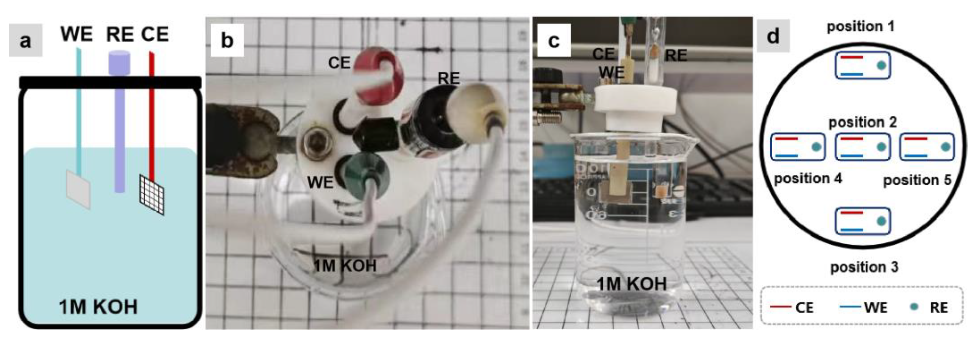
During the electrochemical testing, we kept the three-electrode system as an integrated unit. This implies that the distances of WE to RE, WE to CE, and RE to CE were fixed, and the Ni sheet (WE) was kept parallel to the Pt mesh (CE), as shown in Figure 1a–c. We initially used a small cylindrical container with a diameter of ~5.5 cm and a height of ~7.5 cm as the electrolyte container. The three-electrode system was placed into the electrolyte container, with the WE and CE aligned along a central axis of the container. The electrode position with the CE near and approximately parallel to the container wall served as the starting point (position 1), and then the container was moved to change the position of the three-electrode system in the container according to the position trajectory shown in Figure 1d.
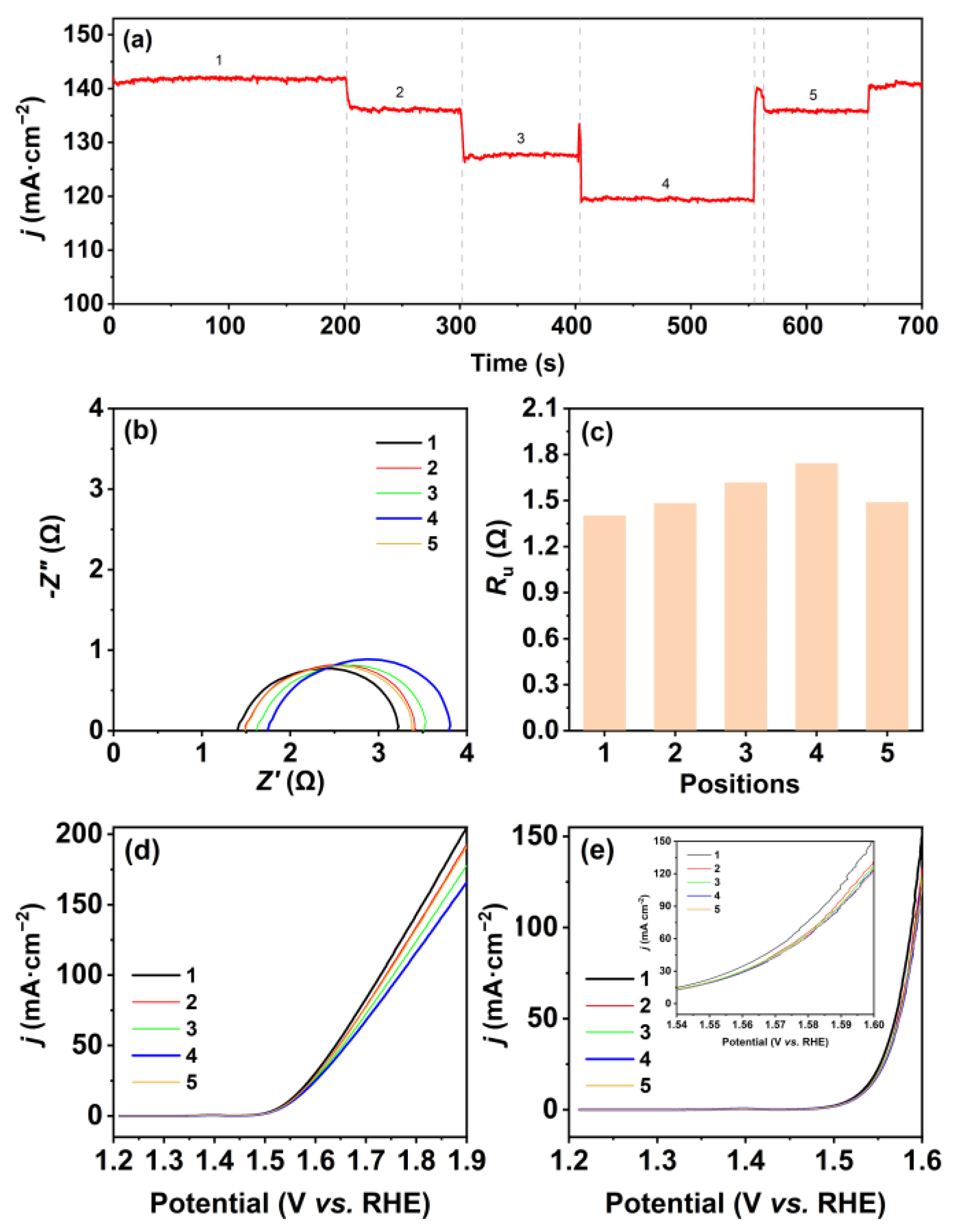
The changes in current density were recorded through the chronoamperometric curve while moving. As shown in Figure 2a, the current density is the highest when the three-electrode system is put at position 1, followed by a 3.5% decrease at position 2, where the WE is located in the center of the container. Another decline in current density with 6.6% is found at position 3, where the CE is placed parallel to and adjacent to the container wall. The current density drops to the lowest value when the WE and CE are located vertically close to the container wall (position 4) and then increased to a similar level to that at position 5, where the RE is near the container wall. The current density can be restored to its initial level when the electrode is relocated back to position 1. This trend was consistent with the results of polarization curves before iRu compensation. As shown in Figure 2d, the polarization curve of the WE at position 1 is located at the top, while the polarization curve of the WE at position 5 is situated at the bottom. Additionally, the polarization curve of the WE at position 3 is positioned below the curves of the WE at position 2 and 4. Ru is responsible for correcting the uncompensated potential drop due to the ionic current flowing through the electrolyte as between the WE and the RE [28]. We suspect the Ru value in different locations of the electrolytic container may vary due to the concentration boundary layer of electrolyte. So, we obtained their corresponding Ru values from Nyquist plots (Figure 2b), which are listed in Figure 2c. The Ru reaches its peak at position 1 with minimum current density and, conversely, the Ru is at its lowest at position 4, experiencing the highest current density. After iRu corrected, the differences in the potential between different positions have significantly decreased, as exhibited in Figure 2e. This indicates that the differences in potentials at different positions are mainly caused by Ru. In addition, a slight difference is still observed in overpotential between the electrodes at position 1 and the electrodes at other positions, which can be ascribed to their different gas diffusion resistances.
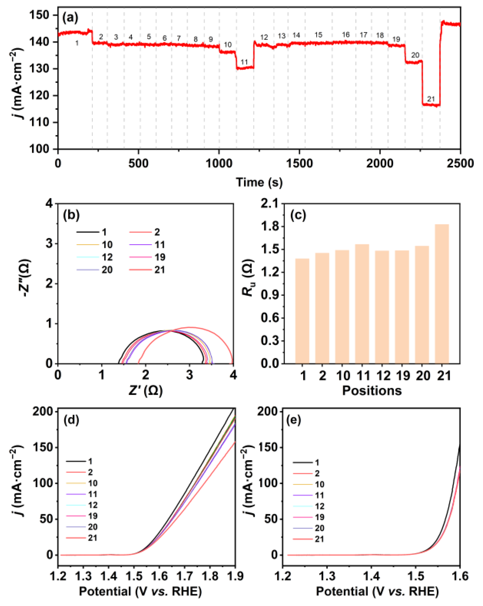
Because of the constrained space within the small electrolytic container and the limited availability of adjustable positions for the three-electrode system, we then employed a bigger container with a diameter of ~12.5 cm and a height of ~7.5 cm to investigate the changes in the current density at different positions (Figure 3a,b). The position trajectory of the electrode system in the bigger electrolytic container is shown in Figure 3c. As expected, the chronoamperometric curve shows multiple steps with the current density changing from 145 to 116.6 mA cm−2 when moving in the electrolytic container (Figure 4a). The current density starts at its peak when the electrode system is at position 1, where the WE and CE lie on the central axis and the CE is near the container wall. A drop of 2.7% in the current density is found when the electrodes move to position 2, followed by infinitesimal fluctuation around 138 mA cm−2 from position 3 to position 9. Then, the current density decreases by 1.4% at position 10 and further decreases by 4.4% at position 11, which is the opposite of position 1, with the WE near the container wall. The current density recovered to 138 mA cm−2 when the electrodes move to position 12, where the RE is near the container wall whereas the WE and CE are vertical to the wall. Prior to the electrodes reaching position 19, the current density undergoes marginal fluctuations. The current density decreases by 4.3% at position 20 and, subsequently, it drops by 12% to reach its lowest value at position 21, where the WE and CE are vertically positioned close to the container wall. The results align with the variation trend of polarization curves prior to iRu compensation, as well as being in line with the results of small electrolytic container experiments (Figure 2a and Figure 4d).
As expected, the variation in Ru is likewise in agreement with the results from the small electrolytic container experiments, i.e., the resistance is lowest at the position that shows the highest current density and vice versa. The values of Ru and the polarization curves corrected by iRu are shown in Figure 4c,e. It can be seen that the fluctuations in current density that occur at different positions during the chronoamperometry test are mainly attributed to alterations in Ru magnitude; therefore, the polarization curves after iRu compensation are nearly coincident for the WE at most positions, except for position 1. The Ru can be calculated by Equation (1) for a simple planar electrode:
R u = x κ A
where x is the distance from the tip of RE to WE, A is the area of the WE, and κ is the solution conductivity [28,29]. When the distance from the tip of RE to WE and the area of the WE are given fixed values, the Ru become affected by the solution conductivity only. In this work, we treated the three-electrode system as a whole and adjusted the position of the electrode system in the container via moving the container itself, so the distance of the RE tip to WE and the area of the WE are constants; therefore, the Ru variation in different positions in the container is mainly caused by the conductivity of the electrolyte solution in the container, which is related to the concentration of ions in the electrolyte solution [30].
According to the theory of the concentration boundary layer, when a fluid flows past a solid wall, a concentration gradient exists within the fluid in the vertical direction of the wall if there is a dissimilarity between the concentration of a component in the fluid and that of the solid wall [31,32], and the concentration gradient diminishes progressively from the wall towards the mainstream liquid [33]. This results in the variations in Ru at different positions in the container and higher Ru in positions closer to the container wall. From the results of the iRu corrected polarization curves, a majority of curves are overlapped by the compensation (Figure 2e and Figure 4e). However, there are certain curves located above or below the overlapped curves (e.g., the curves of position 1 in the small or big circular container) as a result of the gas diffusion resistance, which can hinder the attainment of accurate and reliable data and interfere with the fair comparison of materials’ overpotential for OER.
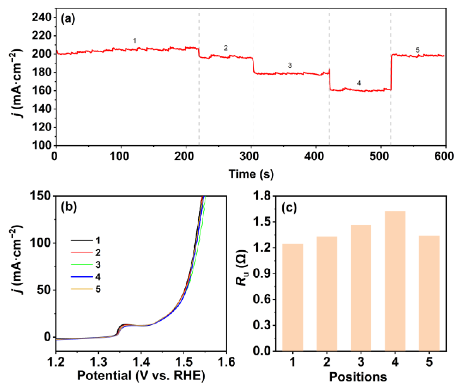
In order to verify the generalization of this phenomenon, we attempted to use NiFe-layered double hydroxide (LDH) grown on Ni foam as the WE, Hg/HgO electrode as the RE, a Pt mesh as the CE, and 1 M NaOH solution as the electrolyte to investigate the fluctuations in current density during the electrode’s movement, and the position trajectory of the three-electrode system in the small circular container was the same as the trajectory in Figure 1d. As show in Figure 5, the electrochemical test results further prove that the variations in Ru at different positions are the primary factor behind the fluctuations in current density during movement. Hence, for fair comparisons and reliable results, it is advisable to place the electrodes in the central region of the electrolytic container and maintain the electrode positions unchanged throughout electrochemical experiments. It is important to emphasize the need to evaluate the Ru whenever there are changes in the container setup during testing.

3. Materials and Methods

3.1. Materials

Potassium hydroxide (KOH), sodium hydroxide (NaOH), nickel nitrate hydrate (Ni(NO3)2·6H2O), ferric nitrate hydrate (Fe(NO3)3·9H2O), ammonium fluoride (NH4F), urea (CH4N2O), acetone, and ethanol were purchased from Sinopharm Chemical Reagent Co., Ltd. (Shanghai, China), which were directly used without further purification. Ni sheets and Ni foam were obtained from Hefei Wenghe Metal Materials Co., Ltd. (Hefei, China). Ni sheets were cleaned with acetone, ethanol, and deionized water for 30 min each before use as electrodes, and Ni foams were pretreated with sonication for 10 min in acetone, hydrochloric acid solution (1 M), deionized water, and ethanol before use.
NiFe-LDH was grown on Ni foam by hydrothermal method according to the previous work [34]. Typically, Ni(NO3)2·6H2O (0.291 g), Fe(NO3)3·9H2O (0.404 g), NH4F (0.224 g), and urea (0.6 g) were dissolved in 30 mL deionized water under stirring. The clear solution and Ni foams were transferred into a 50 mL Teflon-lined stainless-steel autoclave for solvothermal treatment at 120 °C for 12 h, and then the products were washed with water and dried at 70 °C in a vacuum oven.

3.2. Electrochemical Characterizations

Electrochemical measurements were performed in an electrolytic container with a three-electrode system at room temperature (~298 K) by using an electrochemical workstation (CHI 760E). The working electrode was a Ni sheet or NiFeLDH with dimensions of 1 cm × 1 cm, the reference electrode was a Hg/HgO electrode, and the counter electrode was a Pt mesh. OER performance of the Ni sheet was tested in a 1.0 M KOH solution. Prior to conducting the electrochemical measurements, 100 cyclic voltametric (CV) scans were performed to activate the working electrode at a scan rate of 50 mV s−1 within the voltage range of 0.3 to 1.0 V (vs. RHE). After electrochemical preactivation, the current change at different positions of the electrode was observed through chronoamperometry performed at 0.9 V (vs. Hg/HgO electrode). The values of Ru at different positions were tested by electrochemical impedance spectroscopy (EIS) measurements, which were carried out at 0.65 V (vs. Hg/HgO electrode) from 100 kHz to 0.1 Hz. Polarization curves were obtained using LSV at a scan rate of 2 mV s−1. The measured potentials were converted to the RHE scale, according to Equation (2), and the potential drops generated from Ru were manually corrected by following Ohm’s law, according to Equation (3):
ERHE = EHg/HgO + 0.0592 pH + 0.098 V,
ERHE (corrected) = ERHE (uncorrected)iRu,

4. Conclusions

We have employed a movable electrolyte container setup to gain insights into the effects of electrode positions in the electrolytic container for the accurate evaluation of an OER electrocatalyst. The results indicate that the current density fluctuations when adjusting the electrodes’ position in the container are primarily caused by their different iRu drop and the gas diffusion resistance. The Ru values at different positions, along with the recorded LSV curves before and after performing iRu compensation, unveil a clear correlation between Ru and the position of the electrodes in the container. We also observed that the gas diffusion is significantly higher when the electrode is placed parallel to the container compared to the positions vertical to the container wall. For accurate data analysis and fair comparisons, the electrode positions are highly recommended to be fixed in the central region in the electrolytic container and, if any movement occurs, it will be necessary to remeasure the resistance. Moreover, it is imperative to establish a standard electrolyzer setup for electrochemical assessments in the electrochemical community.

Author Contributions

Conceptualization, Y.L. and F.Z.; methodology, F.Z., S.Z. and X.C.; validation, S.Z., X.C. and Z.L.; formal analysis, X.C. and J.Z.; investigation, J.Z.; data curation, Y.Z.; writing—original draft preparation, F.Z. and Y.Z.; writing—review and editing, Y.L. and Y.Z.; supervision, Y.L.; project administration, Y.L.; funding acquisition, Y.L and Y.Z. All authors have read and agreed to the published version of the manuscript.

Funding

This research was funded by “Pioneer” and “Leading Goose” R&D Program of Zhejiang (No. 2022C01029), National Natural Science Foundation of China (No. 52271232), Bellwethers Project of Zhejiang Research and Development Plan (No. 2022C01158), Ningbo S&T Innovation 2025 Major Special Program (Nos. 2020Z107, 2022Z205), Natural Science Foundation of Zhejiang Province (Nos. LY21E020008, LXR22B030001 and LD21E020001), Youth Innovation Promotion Association, CAS (No. 2020300), Ningbo Natural Science Foundation (No. 2023J354), and Jiangbei Science and Technology planning project (No. 202301A09).

Institutional Review Board Statement

Not applicable.

Informed Consent Statement

Not applicable.

Data Availability Statement

Data are contained within the article.

Conflicts of Interest

Author Fan Zhang was employed by the Power China Huadong Engineering Corporation Limited and Key Laboratory of Far-shore Wind Power Technology of Zhejiang Province. The remaining authors declare that the research was conducted in the absence of any commercial or financial relationships that could be construed as a potential conflict of interest.

References

  1. Hassan, Q.; Sameen, A.Z.; Salman, H.M.; Jaszczur, M.; Al-Jiboory, A.K. Hydrogen energy future: Advancements in storage technologies and implications for sustainability. J. Energy Storage 2023, 72, 108404. [Google Scholar] [CrossRef]
  2. Megía, P.J.; Vizcaíno, A.J.; Calles, J.A.; Carrero, A. Hydrogen Production Technologies: From Fossil Fuels toward Renewable Sources. A Mini Review. Energy Fuels 2021, 35, 16403–16415. [Google Scholar] [CrossRef]
  3. Wang, Y.; Vogel, A.; Sachs, M.; Sprick, R.S.; Wilbraham, L.; Moniz, S.J.A.; Godin, R.; Zwijnenburg, M.A.; Durrant, J.R.; Cooper, A.I.; et al. Current understanding and challenges of solar-driven hydrogen generation using polymeric photocatalysts. Nat. Energy 2019, 4, 746–760. [Google Scholar] [CrossRef]
  4. Zhu, J.; Hu, L.; Zhao, P.; Lee, L.Y.S.; Wong, K.-Y. Recent Advances in Electrocatalytic Hydrogen Evolution Using Nanoparticles. Chem. Rev. 2020, 120, 851–918. [Google Scholar] [CrossRef] [PubMed]
  5. Terlouw, T.; Bauer, C.; McKenna, R.; Mazzotti, M. Large-scale hydrogen production via water electrolysis: A techno-economic and environmental assessment. Energy Environ. Sci. 2022, 15, 3583–3602. [Google Scholar] [CrossRef]
  6. Kibsgaard, J.; Chorkendorff, I. Considerations for the scaling-up of water splitting catalysts. Nat. Energy 2019, 4, 430–433. [Google Scholar] [CrossRef]
  7. Song, J.; Wei, C.; Huang, Z.-F.; Liu, C.; Zeng, L.; Wang, X.; Xu, Z.J. A review on fundamentals for designing oxygen evolution electrocatalysts. Chem. Soc. Rev. 2020, 49, 2196–2214. [Google Scholar] [CrossRef] [PubMed]
  8. Li, H.; Pan, Y.; Wu, L.; He, R.; Qin, Z.; Luo, S.; Yang, L.; Zeng, J. IrO2 deposited on RuO2 as core-shell structured RuO2@IrO2 for oxygen evolution reaction in electrochemical water electrolyzer. Mol. Catal. 2023, 551, 113619. [Google Scholar] [CrossRef]
  9. Wu, Z.-Y.; Chen, F.-Y.; Li, B.; Yu, S.-W.; Finfrock, Y.Z.; Meira, D.M.; Yan, Q.-Q.; Zhu, P.; Chen, M.-X.; Song, T.-W.; et al. Non-iridium-based electrocatalyst for durable acidic oxygen evolution reaction in proton exchange membrane water electrolysis. Nat. Mater. 2023, 22, 100–108. [Google Scholar] [CrossRef]
  10. Qin, Y.; Yu, T.; Deng, S.; Zhou, X.-Y.; Lin, D.; Zhang, Q.; Jin, Z.; Zhang, D.; He, Y.-B.; Qiu, H.-J.; et al. RuO2 electronic structure and lattice strain dual engineering for enhanced acidic oxygen evolution reaction performance. Nat. Commun. 2022, 13, 3784. [Google Scholar] [CrossRef]
  11. Mamaca, N.; Mayousse, E.; Arrii-Clacens, S.; Napporn, T.W.; Servat, K.; Guillet, N.; Kokoh, K.B. Electrochemical activity of ruthenium and iridium based catalysts for oxygen evolution reaction. Appl. Catal. B Environ. 2012, 111–112, 376–380. [Google Scholar] [CrossRef]
  12. Yang, L.; Liu, Z.; Zhu, S.; Feng, L.; Xing, W. Ni-based layered double hydroxide catalysts for oxygen evolution reaction. Mater. Today Phys. 2021, 16, 100292. [Google Scholar] [CrossRef]
  13. Khan, N.A.; Rashid, N.; Junaid, M.; Zafar, M.N.; Faheem, M.; Ahmad, I. NiO/NiS Heterostructures: An Efficient and Stable Electrocatalyst for Oxygen Evolution Reaction. ACS Appl. Energy Mater. 2019, 2, 3587–3594. [Google Scholar] [CrossRef]
  14. He, D.; Song, X.; Li, W.; Tang, C.; Liu, J.; Ke, Z.; Jiang, C.; Xiao, X. Active Electron Density Modulation of Co3O4-Based Catalysts Enhances their Oxygen Evolution Performance. Angew. Chem. Int. Ed. 2020, 59, 6929–6935. [Google Scholar] [CrossRef] [PubMed]
  15. Li, S.; Hao, X.; Abudula, A.; Guan, G. Nanostructured Co-based bifunctional electrocatalysts for energy conversion and storage: Current status and perspectives. J. Mater. Chem. A 2019, 7, 18674–18707. [Google Scholar] [CrossRef]
  16. Xu, X.; Su, C.; Shao, Z. Fundamental Understanding and Application of Ba0.5Sr0.5Co0.8Fe0.2O3−δ Perovskite in Energy Storage and Conversion: Past, Present, and Future. Energy Fuels 2021, 35, 13585–13609. [Google Scholar] [CrossRef]
  17. Xu, X.; Wang, W.; Zhou, W.; Shao, Z. Recent Advances in Novel Nanostructuring Methods of Perovskite Electrocatalysts for Energy-Related Applications. Small Methods 2018, 2, 1800071. [Google Scholar] [CrossRef]
  18. Nong, H.N.; Falling, L.J.; Bergmann, A.; Klingenhof, M.; Tran, H.P.; Spöri, C.; Mom, R.; Timoshenko, J.; Zichittella, G.; Knop-Gericke, A.; et al. Key role of chemistry versus bias in electrocatalytic oxygen evolution. Nature 2020, 587, 408–413. [Google Scholar] [CrossRef]
  19. Kang, W.; Wei, R.; Yin, H.; Li, D.; Chen, Z.; Huang, Q.; Zhang, P.; Jing, H.; Wang, X.; Li, C. Unraveling Sequential Oxidation Kinetics and Determining Roles of Multi-Cobalt Active Sites on Co3O4 Catalyst for Water Oxidation. J. Am. Chem. Soc. 2023, 145, 3470–3477. [Google Scholar] [CrossRef]
  20. Huang, Z.-F.; Song, J.; Du, Y.; Xi, S.; Dou, S.; Nsanzimana, J.M.V.; Wang, C.; Xu, Z.J.; Wang, X. Chemical and structural origin of lattice oxygen oxidation in Co–Zn oxyhydroxide oxygen evolution electrocatalysts. Nat. Energy 2019, 4, 329–338. [Google Scholar] [CrossRef]
  21. Righi, G.; Plescher, J.; Schmidt, F.-P.; Campen, R.K.; Fabris, S.; Knop-Gericke, A.; Schlögl, R.; Jones, T.E.; Teschner, D.; Piccinin, S. On the origin of multihole oxygen evolution in haematite photoanodes. Nat. Catal. 2022, 5, 888–899. [Google Scholar] [CrossRef]
  22. Haase, F.T.; Bergmann, A.; Jones, T.E.; Timoshenko, J.; Herzog, A.; Jeon, H.S.; Rettenmaier, C.; Cuenya, B.R. Size effects and active state formation of cobalt oxide nanoparticles during the oxygen evolution reaction. Nat. Energy 2022, 7, 765–773. [Google Scholar] [CrossRef]
  23. Wang, X.; Xi, S.; Huang, P.; Du, Y.; Zhong, H.; Wang, Q.; Borgna, A.; Zhang, Y.-W.; Wang, Z.; Wang, H.; et al. Pivotal role of reversible NiO6 geometric conversion in oxygen evolution. Nature 2022, 611, 702–708. [Google Scholar] [CrossRef] [PubMed]
  24. Jia, H.; Yao, N.; Yu, C.; Cong, H.; Luo, W. Unveiling the Electrolyte Cations Dependent Kinetics on CoOOH-Catalyzed Oxygen Evolution Reaction. Angew. Chem. Int. Ed. 2023, 62, e202313886. [Google Scholar] [CrossRef] [PubMed]
  25. Zhao, K.; Tao, Y.; Fu, L.; Li, C.; Xu, B. Bifunctional Near-Neutral Electrolyte Enhances Oxygen Evolution Reaction. Angew. Chem. Int. Ed. 2023, 62, e202308335. [Google Scholar] [CrossRef]
  26. Liang, Q.; Brocks, G.; Bieberle-Hütter, A. Oxygen evolution reaction (OER) mechanism under alkaline and acidic conditions. J. Phys. Energy 2021, 3, 026001. [Google Scholar] [CrossRef]
  27. Tang, J.; Xu, X.; Tang, T.; Zhong, Y.; Shao, Z. Perovskite-Based Electrocatalysts for Cost-Effective Ultrahigh-Current-Density Water Splitting in Anion Exchange Membrane Electrolyzer Cell. Small Methods 2022, 6, 2201099. [Google Scholar] [CrossRef]
  28. Stevens, M.B.; Enman, L.J.; Batchellor, A.S.; Cosby, M.R.; Vise, A.E.; Trang, C.D.M.; Boettcher, S.W. Measurement Techniques for the Study of Thin Film Heterogeneous Water Oxidation Electrocatalysts. Chem. Mater. 2017, 29, 120–140. [Google Scholar] [CrossRef]
  29. Bard, A.J.; Faulkner, L.R. Electrochemical Methods: Fundamentals and Applications, 2nd ed.; John Wiley & Sons: New York, NY, USA, 2001. [Google Scholar]
  30. Zhang, W.; Chen, X.; Wang, Y.; Wu, L.; Hu, Y. Experimental and Modeling of Conductivity for Electrolyte Solution Systems. ACS Omega 2020, 5, 22465–22474. [Google Scholar] [CrossRef]
  31. Pérez-Herranz, V.; Guiñón, J.L.; García-Antón, J. A new technique for the visualization of the concentration boundary layer in an electrodialysis cell. J. Appl. Electrochem. 2000, 30, 809–816. [Google Scholar] [CrossRef]
  32. Zhou, Y. Materials Engineering Fundamentals, 1st ed.; Wuhan University of Technology Press: Wuhan, China, 2011. [Google Scholar]
  33. Zhu, M.; Yu, Q. Thermal Engineering Fundamentals, 1st ed.; Wuhan University of Technology Press: Wuhan, China, 2014. [Google Scholar]
  34. Wu, B.; Gong, S.; Lin, Y.; Li, T.; Chen, A.; Zhao, M.; Zhang, Q.; Chen, L. A Unique NiOOH@FeOOH Heteroarchitecture for Enhanced Oxygen Evolution in Saline Water. Adv. Mater. 2022, 34, 2108619. [Google Scholar] [CrossRef] [PubMed]
Figure 1. (a) Schematic of the container setup with WE, CE, and RE in 1 M KOH aqueous solution; (b) top-view photo and (c) side-view photo of the three-electrode system in the small electrolyte container; (d) the position trajectory of the three-electrode system in the small circular container (Molecules 28 08143 i001: the three-electrode system).
Molecules 28 08143 g001
Figure 2. (a) Chronoamperometric curve for the WE at different positions in the small electrolytic container at 0.9 V (vs. Hg/HgO electrode); (b) Nyquist plots of the WE and (c) the responding Ru at different positions in the small electrolytic container; OER polarization curves of the WE (d) without iRu compensation and (e) with iRu compensation for the WE at different positions in the small circular container after chronoamperometry. Note: the number 1–5 refer to the numbers of different positions.
Molecules 28 08143 g002
Figure 3. (a) Top-view photo and (b) side-view photo of the three-electrode system in the big circular container; (c) the position trajectory of the three-electrode system in the big circular container (Molecules 28 08143 i002: the three-electrode system).
Molecules 28 08143 g003
Figure 4. (a) Chronoamperometric curve for the WE at different positions in the big electrolytic container at 0.9 V (vs. Hg/HgO electrode); (b) Nyquist plots of the WE and (c) the responding Ru at different positions in the big circular container; OER polarization curves of the WE (d) without iRu compensation and (e) with iRu compensation for the WE at different positions in the big circular container after chronoamperometry. Note: the numbers 1–21 refer to the numbers of different positions.
Molecules 28 08143 g004
Figure 5. (a) Chronoamperometric curve for the NiFeLDH at different positions in the small electrolytic container at 0.9 V (vs. Hg/HgO electrode); (b) OER polarization curves of the NiFeLDH with iRu compensation and (c) the responding Ru at different positions in the small circular container after chronoamperometry. Note: the numbers 1–5 refer to the numbers of different positions.
Molecules 28 08143 g005
Disclaimer/Publisher’s Note: The statements, opinions and data contained in all publications are solely those of the individual author(s) and contributor(s) and not of MDPI and/or the editor(s). MDPI and/or the editor(s) disclaim responsibility for any injury to people or property resulting from any ideas, methods, instructions or products referred to in the content.