
Recent Progress in Silicon−Based Materials for Performance−Enhanced Lithium−Ion Batteries

 and
and
Abstract
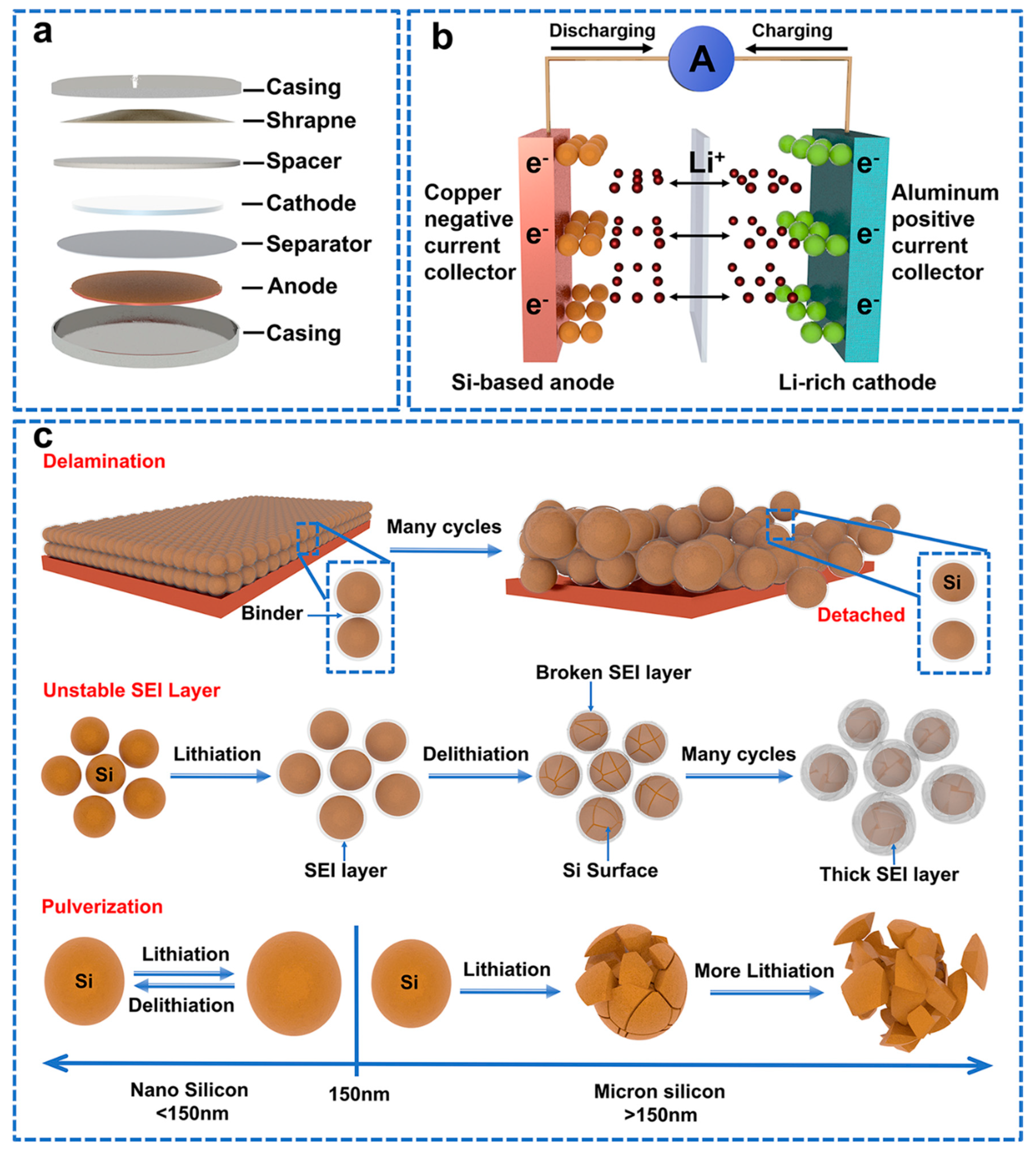
:1. Introduction
2. Silicon−Based Material Modification Strategies
2.1. Micro/Nanometer Architecture Design
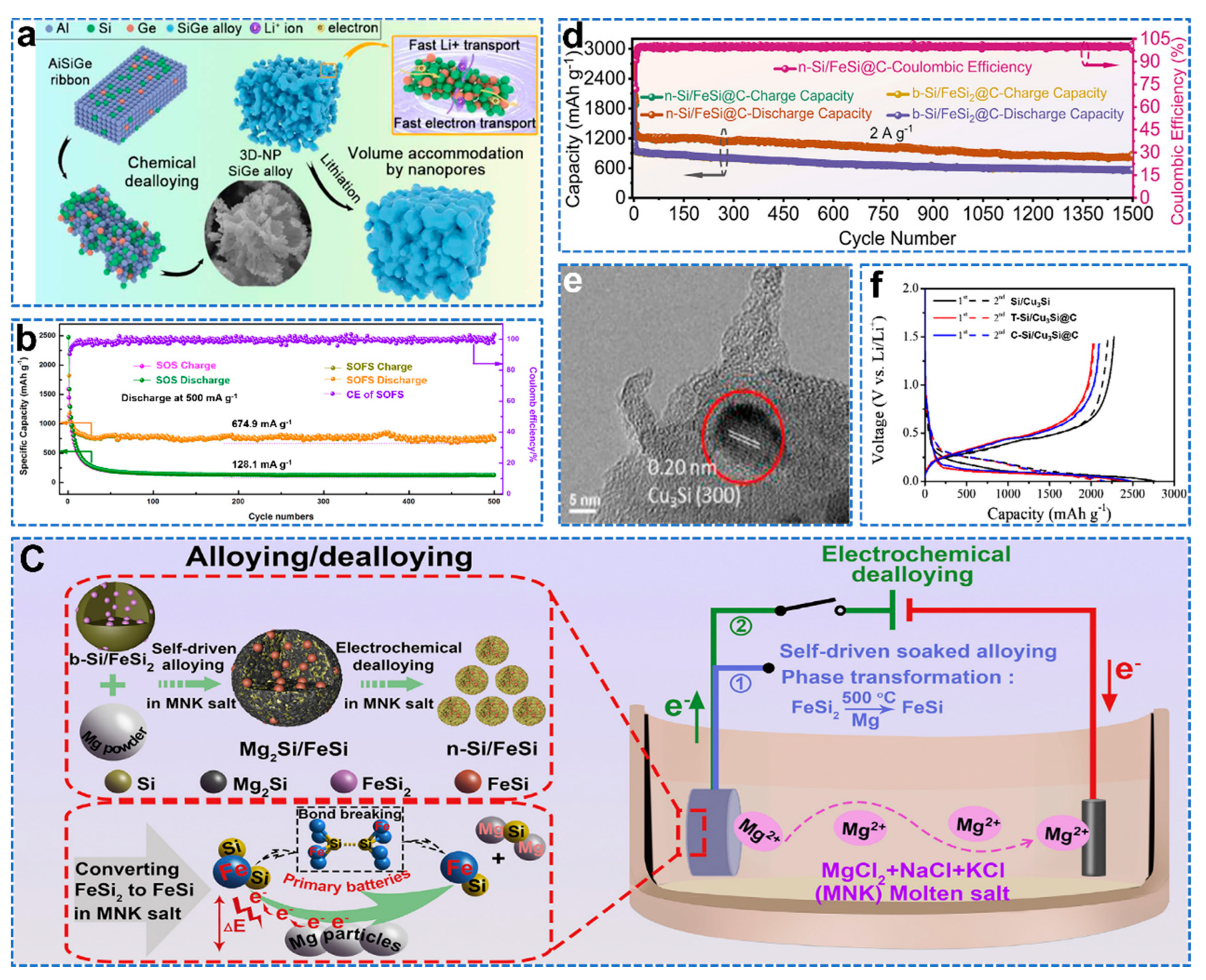
2.2. Si Alloy Structure Control
2.3. SiOx (0 < x < 2)
2.4. Composite Structure of Si/Si Oxide

3. Advanced Modification Strategies for Si−Based Cells
3.1. Pre−Lithiation
3.2. Surface Engineering

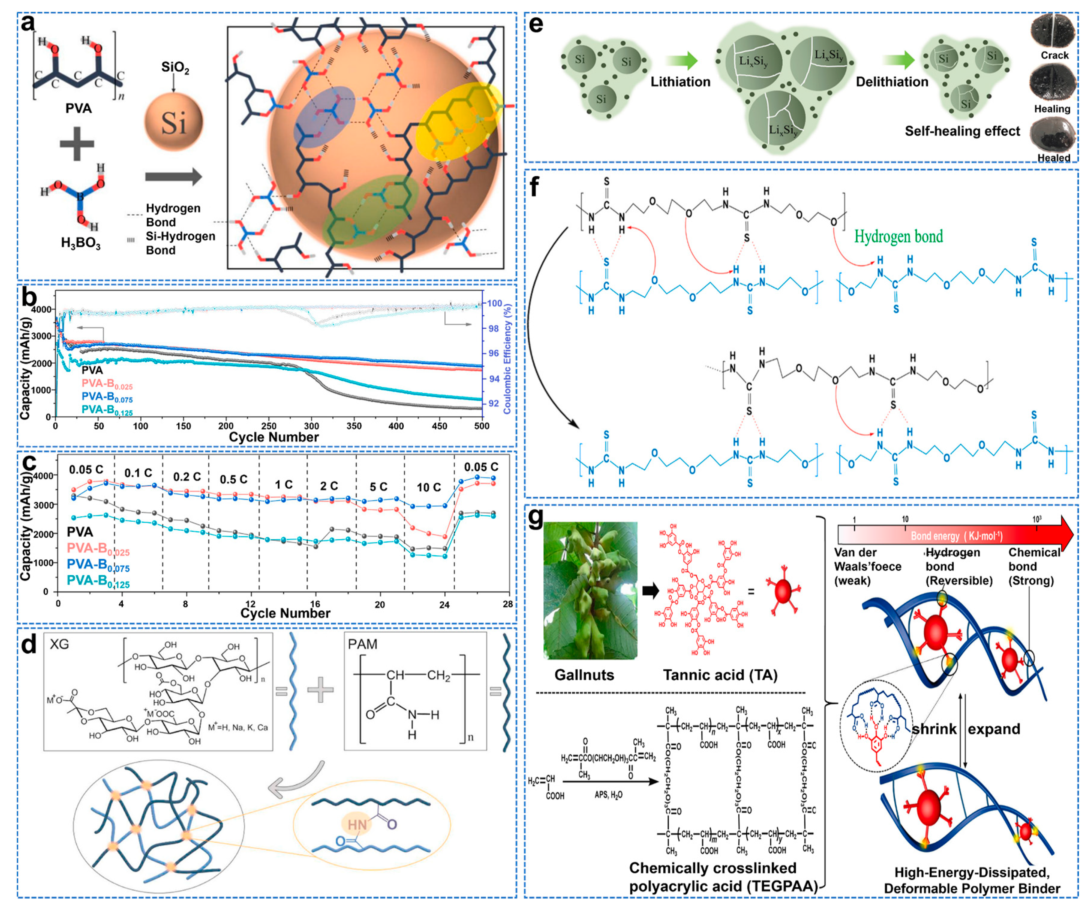
3.3. Binders

3.4. Electrolyte and Electrolyte Additives
3.5. Collectors
4. Advanced Characterization Techniques and Mechanisms
4.1. Morphological Changes and Lithiation Mechanism of a Pure Si Anode
4.2. Structural Controlling and Lithiation/De−Lithiation Mechanism of Si/C Composites

4.3. Formation Mechanism of SEI on Si−Based Anodes
4.4. Optimal Surface Oxide Layers of Si−Based Anodes
5. Conclusions and Perspectives
Author Contributions
Funding
Institutional Review Board Statement
Informed Consent Statement
Data Availability Statement
Conflicts of Interest
References
- Lu, L.; Han, X.; Li, J.; Hua, J.; Ouyang, M. A review on the key issues for lithium−ion battery management in electric vehicles. J. Power Sources 2013, 226, 272–288. [Google Scholar] [CrossRef]
- Fasakin, O.; Oyedotun, K.O.; Kebede, M.; Rohwer, M.; Roux, L.L.; Mathe, M.; Eleruja, M.A.; Ajayi, E.O.B.; Manyala, N. Preparation and physico−chemical investigation of anatase TiO2 nanotubes for a stable anode of lithium−ion battery. Energy Rep. 2020, 6, 92–101. [Google Scholar] [CrossRef]
- Zhang, Y.; Zhang, X.G.; Zhang, H.L.; Zhao, Z.G.; Li, F.; Liu, C.; Cheng, H.M. Composite anode material of silicon/graphite/carbon nanotubes for Li−ion batteries. Electrochim. Acta 2006, 51, 4994–5000. [Google Scholar] [CrossRef]
- Jung, C.H.; Kim, K.H.; Hong, S.H. Stable silicon anode for lithium−ion batteries through covalent bond formation with a binder via esterification. ACS Appl. Mater. Inter. 2019, 11, 26753–26763. [Google Scholar] [CrossRef]
- Rehman, W.U.; Wang, H.; Manj RZ, A.; Luo, W.; Yang, J. When silicon materials meet natural sources: Opportunities and challenges for low−cost lithium storage. Small 2021, 17, e1904508. [Google Scholar] [CrossRef]
- Ge, M.; Cao, C.; Biesold, G.M.; Sewell, C.D.; Hao, S.M.; Huang, J.; Zhang, W.; Lai, Y.; Lin, Z. Recent advances in silicon−based electrodes: From fundamental research toward practical applications. Adv. Mater. 2021, 33, e2004577. [Google Scholar] [CrossRef]
- Boukamp, B.A.; Lesh, G.C.; Huggins, R.A. All-solid lithium electrodes with mixed-conductor matrix. J. Electrochem. Soc. 2019, 128, 725–729. [Google Scholar] [CrossRef]
- Uchida, S.; Mihashi, M.; Yamagata, M.; Ishikawa, M. Electrochemical properties of non-nano-silicon negative electrodes prepared with a polyimide binder. J. Power Sources 2015, 273, 118–122. [Google Scholar] [CrossRef]
- Agubra, V.A.; Fergus, J.W. The formation and stability of the solid electrolyte interface on the graphite anode. J. Power Sources 2014, 268, 153–162. [Google Scholar] [CrossRef]
- Li, P.; Zhao, G.; Zheng, X.; Xu, X.; Yao, C.; Sun, W.; Dou, S.X. Recent progress on silicon-based anode materials for practical lithium-ion battery applications. Energy Storage Mater. 2018, 15, 422–446. [Google Scholar] [CrossRef]
- Shen, X.; Tian, Z.; Fan, R.; Shao, L.; Zhang, D.; Cao, G.; Kou, L.; Bai, Y. Research progress on silicon/carbon composite anode materials for lithium-ion battery. J. Energy Chem. 2018, 27, 1067–1090. [Google Scholar] [CrossRef] [Green Version]
- Thackeray, M.M.; Wolverton, C.; Isaacs, E.D. Electrical energy storage for transportation-approaching the limits of, and going beyond, lithium-ion batteries. Energy Environ. Sci. 2012, 5, 7854–7863. [Google Scholar] [CrossRef]
- Meng, Q.; Li, G.; Yue, J.; Xu, Q.; Yin, Y.X.; Guo, Y.G. High-performance lithiated SiOx anode obtained by a controllable and efficient prelithiation strategy. ACS Appl. Mater. Inter. 2019, 11, 32062–32068. [Google Scholar] [CrossRef]
- Wang, J.; Liao, L.; Li, Y.; Zhao, J.; Shi, F.; Yan, K.; Pei, A.; Chen, G.; Li, G.; Lu, Z.; et al. Shell-protective secondary silicon nanostructures as pressure-resistant high-volumetric-capacity anodes for lithium-ion batteries. Nano Lett. 2018, 18, 7060–7065. [Google Scholar] [CrossRef]
- Chan, C.K.; Peng, H.; Liu, G.; McIlwrath, K.; Zhang, X.F.; Huggins, R.A.; Cui, Y. High-performance lithium battery anodes using silicon nanowires. Nat. Nanotechnol. 2008, 3, 31–35. [Google Scholar] [CrossRef]
- Tian, H.; Tian, H.; Yang, W.; Zhang, F.; Yang, W.; Zhang, Q.; Wang, Y.; Liu, J.; Silva SR, P.; Liu, H.; et al. Stable hollow-structured silicon suboxide-based anodes toward high-performance lithium-ion batteries. Adv. Funct. Mater. 2021, 31, 2101796. [Google Scholar] [CrossRef]
- Zhang, W.; Weng, Y.; Shen, W.; Lv, R.; Kang, F.; Huang, Z.-H. Scalable synthesis of lotus-seed-pod-like Si/SiOx@CNF: Applications in freestanding electrode and flexible full lithium-ion batteries. Carbon 2020, 158, 163–171. [Google Scholar] [CrossRef]
- Kowalski, D.; Mallet, J.; Thomas, S.; Nemaga, A.W.; Michel, J.; Guery, C.; Molinari, M.; Morcrette, M. Electrochemical synthesis of 1D core-shell Si/TiO2 nanotubes for lithium ion batteries. J. Power Sources 2017, 361, 243–248. [Google Scholar] [CrossRef]
- Zhou, J.; Lin, N.; Han, Y.; Zhou, J.; Zhu, Y.; Du, J.; Qian, Y. Cu3Si@Si core-shell nanoparticles synthesized using a solid-state reaction and their performance as anode materials for lithium ion batteries. Nanoscale 2015, 7, 15075–15079. [Google Scholar] [CrossRef]
- Jin, Y.; Zhu, B.; Lu, Z.; Liu, N.; Zhu, J. Challenges and recent progress in the development of Si anodes for lithium-ion battery. Adv. Energy Mater. 2017, 7, 422–446. [Google Scholar] [CrossRef] [Green Version]
- SShih, J.-Y.; Chen, Y.-R.; James Li, Y.-J.; Hung, T.-F.; Hsu, L.-F.; Tsai, Y.-D.; Ramaraj, S.K.; Jose, R.; Karuppiah, C.; Yang, C.-C. Suppressed volume change of a spray-dried 3D spherical-like Si/graphite composite anode for high-rate and long-term lithium-ion batteries. ACS Sustain. Chem. Eng. 2022, 10, 12706–12720. [Google Scholar] [CrossRef]
- Liu, Y.-H.; Chen, Y.-L.; Chen, Y.-S.; Huang, S.-M.; Huang, H.-M.; Lin, S.-J.; Yang, C.-Y. Utilization of Si/SiOx/Al2O3 material from recycled solar cells for high-performance lithium-ion battery anode. Green Chem. 2022, 24, 5151–5161. [Google Scholar] [CrossRef]
- Zhang, Z.; Sun, S.; Zhang, W.; Xu, J.; Wang, X.; Fang, C.; Li, Q.; Han, J. Internally inflated core-buffer-shell structural Si/EG/C composites as high-performance anodes for lithium-ion batteries. Sci. China Mater. 2022, 65, 2949–2957. [Google Scholar] [CrossRef]
- Kwon, T.W.; Choi, J.W.; Coskun, A. The emerging era of supramolecular polymeric binders in silicon anodes. Chem. Soc. Rev. 2018, 47, 2145–2164. [Google Scholar] [CrossRef] [Green Version]
- Bi, X.; Tang, T.; Shi, X.; Ge, X.; Wu, W.; Zhang, Z.; Wang, J. One-step synthesis of multi-core-void@shell structured silicon anode for high-performance lithium-ion batteries. Small 2022, 18, e2200796. [Google Scholar] [CrossRef]
- Lopez, J.; Mackanic, D.G.; Cui, Y.; Bao, Z. Designing polymers for advanced battery chemistries. Nat. Rev. Mater. 2019, 4, 312–330. [Google Scholar] [CrossRef] [Green Version]
- Peng, J.; Li, W.; Wu, Z.; Li, H.; Zeng, P.; Chen, G.; Chang, B.; Zhang, X.; Wang, X. Si/C composite embedded nano-Si in 3D porous carbon matrix and enwound by conductive CNTs as anode of lithium-ion batteries. Sustain. Mater. Techno. 2022, 32, e00410. [Google Scholar] [CrossRef]
- An, Y.; Tian, Y.; Zhang, Y.; Wei, C.; Tan, L.; Zhang, C.; Cui, N.; Xiong, S.; Feng, J.; Qian, Y. Two-dimensional silicon/carbon from commercial alloy and CO2 for lithium storage and flexible Ti3C2Tx MXene-based lithium-metal batteries. ACS Nano 2020, 14, 17574–17588. [Google Scholar] [CrossRef]
- Huang, X.; Wang, R.; Jiao, T.; Zou, G.; Zhan, F.; Yin, J.; Zhang, L.; Zhou, J.; Peng, Q. Facile preparation of hierarchical AgNP-loaded MXene/Fe3O4/polymer nanocomposites by electrospinning with enhanced catalytic performance for wastewater treatment. ACS Omega 2019, 4, 1897–1906. [Google Scholar] [CrossRef] [Green Version]
- Zhu, R.; Wang, Z.; Hu, X.; Liu, X.; Wang, H. Silicon in hollow carbon nanospheres assembled microspheres cross-linked with N-doped carbon fibers toward a binder free, high performance, and flexible anode for lithium-ion batteries. Adv. Funct. Mater. 2021, 31, 2101487. [Google Scholar] [CrossRef]
- Huang, X.; Ding, Y.; Li, K.; Guo, X.; Zhu, Y.; Zhang, Y.; Bao, Z. Spontaneous formation of the conformal carbon nanolayer coated Si nanostructures as the stable anode for lithium-ion batteries from silica nanomaterials. J. Power Sources 2021, 496, 229833. [Google Scholar] [CrossRef]
- Yan, Z.; Guo, J. High-performance silicon-carbon anode material via aerosol spray drying and magnesiothermic reduction. Nano Energy 2019, 63, 103845. [Google Scholar] [CrossRef]
- Zhao, J.; Rui, B.; Wei, W.; Nie, P.; Chang, L.; Xue, X.; Wang, L.; Jiang, J. Encapsulating silicon particles by graphitic carbon enables high-performance lithium-ion batteries. J. Colloid Interf. Sci. 2022, 607, 1562–1570. [Google Scholar] [CrossRef]
- Wang, D.; Zhou, C.; Cao, B.; Xu, Y.; Zhang, D.; Li, A.; Zhou, J.; Ma, Z.; Chen, X.; Song, H. One-step synthesis of spherical Si/C composites with onion-like buffer structure as high-performance anodes for lithium-ion batteries. Energy Storage Mater. 2020, 24, 312–318. [Google Scholar] [CrossRef]
- Ren, Y.; Xiang, L.; Yin, X.; Xiao, R.; Zuo, P.; Gao, Y.; Yin, G.; Du, C. Ultrathin Si nanosheets dispersed in graphene matrix enable stable interface and high rate capability of anode for lithium-ion batteries. Adv. Funct. Mater. 2022, 32, 2110046. [Google Scholar] [CrossRef]
- Tan, Q.; Kong, Z.; Guan, X.; Zhang, L.Y.; Jiao, Z.; Chen, H.C.; Wu, G.; Xu, B. Hierarchical zinc oxide/reduced graphene oxide composite: Preparation route, mechanism study and lithium ion storage. J. Colloid Interf. Sci. 2019, 548, 233–243. [Google Scholar] [CrossRef]
- Seredych, M.; Bandosz, T.J. Mechanism of ammonia retention on graphite oxides: Role of surface chemistry and structure. J. Phys. Chem. C 2007, 111, 15596–15604. [Google Scholar] [CrossRef]
- Hao, Q.; Hou, J.; Ye, J.; Yang, H.; Du, J.; Xu, C. Hierarchical macroporous Si/Sn composite: Easy preparation and optimized performances towards lithium storage. Electrochim. Acta 2019, 306, 427–436. [Google Scholar] [CrossRef]
- Wu, Z.S.; Sun, Y.; Tan, Y.Z.; Yang, S.; Feng, X.; Mullen, K. Three-dimensional graphene-based macro- and mesoporous frameworks for high-performance electrochemical capacitive energy storage. J. Am. Chem. Soc. 2012, 134, 19532–19535. [Google Scholar] [CrossRef]
- Kim, S.Y.; Kim, C.H.; Yang, C.-M. Binder-free silicon anodes wrapped in multiple graphene shells for high-performance lithium-ion batteries. J. Power Sources 2021, 486, 229350. [Google Scholar] [CrossRef]
- Zhu, C.; Zhang, Y.; Wu, Z.; Ma, Z.; Guo, X.; Guo, F.; Zhang, J.; Li, Y. Closely packed Si@C and Sn@C nano-particles anchored by reduced graphene oxide sheet boosting anode performance of lithium ion batteries. J. Mater. Sci. Technol. 2021, 87, 18–28. [Google Scholar] [CrossRef]
- Wang, F.; Hu, Z.; Mao, L.; Mao, J. Nano-silicon @ soft carbon embedded in graphene scaffold: High-performance 3D free-standing anode for lithium-ion batteries. J. Power Sources 2020, 450, 227692. [Google Scholar] [CrossRef]
- Xu, Q.; Sun, J.K.; Yu, Z.L.; Yin, Y.X.; Xin, S.; Yu, S.H.; Guo, Y.G. SiOx encapsulated in graphene bubble film: An ultrastable Li-ion battery anode. Adv. Mater. 2018, 30, e1707430. [Google Scholar] [CrossRef]
- Ge, X.; Li, Z.; Wang, C.; Yin, L. Metal-organic frameworks derived porous core/shell structured ZnO/ZnCo2O4/C hybrids as anodes for high-performance lithium-ion battery. ACS Appl. Mater. Inter. 2015, 7, 26633–26642. [Google Scholar] [CrossRef]
- Guo, X.; Xu, H.; Li, W.; Liu, Y.; Shi, Y.; Li, Q.; Pang, H. Embedding atomically dispersed iron sites in nitrogen-doped carbon frameworks-wrapped silicon suboxide for superior lithium storage. Adv. Sci. 2022, 10, e2206084. [Google Scholar] [CrossRef]
- Luo, H.; Wang, Q.; Wang, Y.; Xu, C.; Wang, B.; Wang, M.; Wu, H.; Zhang, Y. Nano-silicon embedded in MOFs-derived nitrogen-doped carbon/cobalt/carbon nanotubes hybrid composite for enhanced lithium ion storage. Appl. Surf. Sci. 2020, 529, 147134. [Google Scholar] [CrossRef]
- Wang, J.; Luo, X.; Young, C.; Kim, J.; Kaneti, Y.V.; You, J.; Kang, Y.-M.; Yamauchi, Y.; Wu, K.C.W. A glucose-assisted hydrothermal reaction for directly transforming metal-organic frameworks into hollow carbonaceous materials. Chem. Mater. 2018, 30, 4401–4408. [Google Scholar] [CrossRef]
- Wei, Q.; Chen, Y.M.; Hong, X.J.; Song, C.L.; Yang, Y.; Si, L.P.; Zhang, M.; Cai, Y.P. Saclike-silicon nanoparticles anchored in ZIF-8 derived spongy matrix as high-performance anode for lithium-ion batteries. J. Colloid. Interf. Sci. 2020, 565, 315–325. [Google Scholar] [CrossRef]
- Gao, R.; Tang, J.; Yu, X.; Tang, S.; Ozawa, K.; Sasaki, T.; Qin, L.-C. In situ synthesis of MOF-derived carbon shells for silicon anode with improved lithium-ion storage. Nano Energy 2020, 70, 104444. [Google Scholar] [CrossRef]
- Yoon, S.; Lee, S.-I.; Kim, H.; Sohn, H.-J. Enhancement of capacity of carbon-coated Si-Cu3Si composite anode using metal-organic compound for lithium-ion batteries. J. Power Sources 2006, 161, 1319–1323. [Google Scholar] [CrossRef]
- Yang, Y.; Liu, S.; Bian, X.; Feng, J.; An, Y.; Yuan, C. Morphology- and porosity-tunable synthesis of 3D nanoporous SiGe alloy as a high-performance lithium-ion battery anode. ACS Nano 2018, 12, 2900–2908. [Google Scholar] [CrossRef]
- Cheng, J.; Yi, S.; Park, J.S. Oxidation behavior of Nb-Si-B alloys with the NbSi2 coating layer formed by a pack cementation technique. Int. J. Refract. Met. H. 2013, 41, 103–109. [Google Scholar] [CrossRef]
- Bae, J.; Salunkhe, T.T.; Hur, J.; Kim, I.T. Novel carbon-free niobium silicide/oxide nanocomposites for lithium-ion battery anodes. Appl. Mater. Today 2021, 22, 100917. [Google Scholar] [CrossRef]
- Zhang, Y.; Chen, M.; Chen, Z.; Wang, Y.; Li, S.; Duan, P.; Zhong, Y.; Wu, Z.; Guo, X.; Yan, Z.; et al. Constructing cycle-stable Si/TiSi2 composites as anode materials for lithium ion batteries through direct utilization of low-purity Si and Ti-bearing blast furnace slag. J. Alloy. Compd. 2021, 876, 160125. [Google Scholar] [CrossRef]
- Qiu, Z.; Wu, A.; Jin, X.; Zhou, S.; Yu, W.; Huang, H. SiOx encapsulated FeSi2-Si eutectic nanoparticles as durable anode of lithium-ion batteries. Mater. Today Chem. 2021, 21, 100540. [Google Scholar] [CrossRef]
- Ma, Q.; Zhao, Y.; Hu, Z.; Qu, J.; Zhao, Z.; Xie, H.; Xing, P.; Wang, D.; Yin, H. Electrochemically converting micro-sized industrial Si/FeSi2 to nano Si/FeSi for the high-performance lithium-ion battery anode. Mater. Today Energy 2021, 21, 100817. [Google Scholar] [CrossRef]
- Wu, Y.-H.; Huang, J.-L.; Hou, S.-C.; Tsai, M.-C.; Chang, C.-C. Cu3Si enhanced crystallinity and dopamine derived nitrogen doping into carbon coated micron-sized Si/Cu3Si as anode material in lithium-ion batteries. Electrochim. Acta 2021, 387, 138495. [Google Scholar] [CrossRef]
- Xue, H.J.; Wu, Y.Q.; Zou, Y.G.; Shen, Y.B.; Liu, G.; Li, Q.; Yin, D.M.; Wang, L.M.; Ming, J. Unraveling metal oxide role in exfoliating graphite: New strategy to construct high-performance graphene-modified SiOx-based anode for lithium-ion batteries. Adv. Funct. Mater. 2020, 30, 1910657. [Google Scholar] [CrossRef]
- Ge, J.; Tang, Q.; Shen, H.; Zhou, F.; Zhou, H.; Yang, W.; Hong, J.; Xu, B.; Saddique, J. Controllable preparation of disproportionated SiOx/C sheets with 3D network as high-performance anode materials of lithium ion battery. Appl. Surf. Sci. 2021, 552, 149446. [Google Scholar] [CrossRef]
- Zhou, X.M.; Liu, Y.; Ren, Y.; Mu, T.S.; Yin, X.C.; Du, C.Y.; Huo, H.; Cheng, X.Q.; Zuo, P.J.; Yin, G.P. Engineering molecular polymerization for template-free SiOx/C hollow spheres as ultrastable anodes in lithium-ion batteries. Adv. Funct. Mater. 2021, 31, 2101145. [Google Scholar] [CrossRef]
- Xiao, Z.; Yu, C.; Lin, X.; Chen, X.; Zhang, C.; Jiang, H.; Zhang, R.; Wei, F. TiO2 as a multifunction coating layer to enhance the electrochemical performance of SiOx@TiO2@C composite as anode material. Nano Energy 2020, 77, 105082. [Google Scholar] [CrossRef]
- Tan, F.; Guo, H.; Wang, Z.; Niu, X.; Li, X.; Yan, G.; Wang, J.; Peng, W.; Hu, Q. Electrospinning-enabled SiO @TiO2/C fibers as anode materials for lithium-ion batteries. J. Alloy. Compd. 2021, 888, 161635. [Google Scholar] [CrossRef]
- Li, G.; Huang, L.-B.; Yan, M.-Y.; Li, J.-Y.; Jiang, K.-C.; Yin, Y.-X.; Xin, S.; Xu, Q.; Guo, Y.-G. An integral interface with dynamically stable evolution on micron-sized SiOx particle anode. Nano Energy 2020, 74, 161635. [Google Scholar] [CrossRef]
- Xue, H.; Cheng, Y.; Gu, Q.; Wang, Z.; Shen, Y.; Yin, D.; Wang, L.; Huang, G. An SiOx anode strengthened by the self-catalytic growth of carbon nanotubes. Nanoscale 2021, 13, 3808–3816. [Google Scholar] [CrossRef]
- Shi, L.; Wang, W.; Wang, A.; Yuan, K.; Yang, Y. Facile synthesis of scalable pore-containing silicon/nitrogen-rich carbon composites from waste contact mass of organosilane industry as anode materials for lithium-ion batteries. J. Mater. Chem. A 2014, 2, 20213–20220. [Google Scholar] [CrossRef]
- Zhang, K.; Du, W.; Qian, Z.; Lin, L.; Gu, X.; Yang, J.; Qian, Y. SiOx embedded in N-doped carbon nanoslices: A scalable synthesis of high-performance anode material for lithium-ion batteries. Carbon 2021, 178, 202–210. [Google Scholar] [CrossRef]
- Wang, X.; Li, G.; Seo, M.H.; Hassan, F.M.; Hoque, M.A.; Chen, Z. Sulfur atoms bridging few-layered MoS2 with S-doped graphene enable highly robust anode for lithium-ion batteries. Adv. Energy Mater. 2015, 5, 1501106. [Google Scholar] [CrossRef]
- Shi, L.; Li, Y.; Xing, Y.; Lin, R.; Cheng, G.; Ding, J.; Lam, K.H. SiOx microparticles embedded into 3D wrinkled N, S co-doped multilayer graphene sheets as a high-performance anode for long-life full lithium-ion batteries. Electrochim. Acta 2021, 390, 138841. [Google Scholar] [CrossRef]
- Hu, G.; Yu, R.; Liu, Z.; Yu, Q.; Zhang, Y.; Chen, Q.; Wu, J.; Zhou, L.; Mai, L. Surface oxidation layer-mediated conformal carbon coating on Si nanoparticles for enhanced lithium storage. ACS Appl. Mater. Inter. 2021, 13, 3991–3998. [Google Scholar] [CrossRef]
- Xi, F.; Zhang, Z.; Hu, Y.; Li, S.; Ma, W.; Chen, X.; Wan, X.; Chong, C.; Luo, B.; Wang, L. PSi@SiOx/nano-Ag composite derived from silicon cutting waste as high-performance anode material for Li-ion batteries. J. Hazard. Mater. 2021, 414, 125480. [Google Scholar] [CrossRef]
- Lin, X.; Chen, X.; Zhang, F.; Dong, Y.; Chen, X.; Li, A.; Song, H. Constructing 3D interconnected Si/SiOx/C nanorings from polyhedral oligomeric silsesquioxane. Small 2021, 17, e2103926. [Google Scholar] [CrossRef]
- Liu, Y.; Jing, S.X.; Luo, S.H.; Li, S.H. Non-volatile natural products in plant glandular trichomes: Chemistry, biological activities and biosynthesis. Nat. Prod. Rep. 2019, 36, 626–665. [Google Scholar] [CrossRef]
- Ren, W.-F.; Li, J.-T.; Zhang, S.-J.; Lin, A.-L.; Chen, Y.-H.; Gao, Z.-G.; Zhou, Y.; Deng, L.; Huang, L.; Sun, S.-G. Fabrication of multi-shell coated silicon nanoparticles via in-situ electroless deposition as high performance anodes for lithium ion batteries. J. Energy Chem. 2020, 48, 160–168. [Google Scholar] [CrossRef]
- Dai, X.; Liu, H.; Liu, X.; Liu, Z.; Liu, Y.; Cao, Y.; Tao, J.; Shan, Z. Silicon nanoparticles encapsulated in multifunctional crosslinked nano-silica/carbon hybrid matrix as a high-performance anode for Li-ion batteries. Chem. Eng. J. 2021, 418, 160–168. [Google Scholar] [CrossRef]
- An, S.J.; Li, J.; Daniel, C.; Mohanty, D.; Nagpure, S.; Wood, D.L. The state of understanding of the lithium-ion-battery graphite solid electrolyte interphase (SEI) and its relationship to formation cycling. Carbon 2016, 105, 52–76. [Google Scholar] [CrossRef] [Green Version]
- Feng, K.; Li, M.; Liu, W.; Kashkooli, A.G.; Xiao, X.; Cai, M.; Chen, Z. Silicon-based anodes for lithium-ion batteries: From fundamentals to practical applications. Small 2018, 14, 1702737. [Google Scholar] [CrossRef]
- Bärmann, P.; Diehl, M.; Göbel, L.; Ruttert, M.; Nowak, S.; Winter, M.; Placke, T. Impact of the silicon particle size on the pre-lithiation behavior of silicon/carbon composite materials for lithium ion batteries. J. Power Sources 2020, 464, 228224. [Google Scholar] [CrossRef]
- Wetjen, M.; Solchenbach, S.; Pritzl, D.; Hou, J.; Tileli, V.; Gasteiger, H.A. Morphological changes of silicon nanoparticles and the influence of cut off potentials in silicon-graphite electrodes. J. Electrochem. Soc. 2018, 165, A1503–A1514. [Google Scholar] [CrossRef] [Green Version]
- Kim, K.H.; Shon, J.; Jeong, H.; Park, H.; Lim, S.J.; Heo, J.S. Improving the cyclability of silicon anodes for lithium-ion batteries using a simple pre-lithiation method. J. Power Sources 2020, 459, 228066. [Google Scholar] [CrossRef]
- Yoshida, S.; Masuo, Y.; Shibata, D.; Haruta, M.; Doi, T.; Inaba, M. Li pre-doping of amorphous silicon electrode in Li-naphthalene complex solutions. Electrochemistry 2015, 83, 843–845. [Google Scholar] [CrossRef] [Green Version]
- Zhang, X.; Qu, H.; Ji, W.; Zheng, D.; Ding, T.; Qiu, D.; Qu, D. An electrode-level prelithiation of SiO anodes with organolithium compounds for lithium-ion batteries. J. Power Sources 2020, 478, 229067. [Google Scholar] [CrossRef]
- Wood, D.L.; Li, J.; Daniel, C. Prospects for reducing the processing cost of lithium ion batteries. J. Power Sources 2015, 275, 234–242. [Google Scholar] [CrossRef] [Green Version]
- Berhaut, C.L.; Dominguez, D.Z.; Tomasi, D.; Vincens, C.; Haon, C.; Reynier, Y.; Porcher, W.; Boudet, N.; Blanc, N.; Chahine, G.A.; et al. Prelithiation of silicon/graphite composite anodes: Benefits and mechanisms for long-lasting Li-ion batteries. Energy Storage Mater. 2020, 29, 190–197. [Google Scholar] [CrossRef]
- Tanaka, M.; Hooper, J.B.; Bedrov, D. Role of plasticity in mechanical failure of solid electrolyte interphases on nanostructured silicon electrode: Insight from continuum level modeling. ACS Appl. Energy Mater. 2018, 1, 1858–1863. [Google Scholar] [CrossRef]
- Park, J.; Suh, S.; Jeong, S.; Kim, H.-J. New approach for the high electrochemical performance of silicon anode in lithium-ion battery: A rapid and large surface treatment using a high-energy pulsed laser. J. Power Sources 2021, 491, 229573. [Google Scholar] [CrossRef]
- Shi, J.; Gao, H.; Hu, G.; Zhang, Q. Core-shell structured Si@C nanocomposite for high-performance Li-ion batteries with a highly viscous gel as precursor. J. Power Sources 2019, 438, 227001. [Google Scholar] [CrossRef]
- Shi, J.; Jiang, X.; Sun, J.; Ban, B.; Li, J.; Chen, J. A surface-engineering-assisted method to synthesize recycled silicon-based anodes with a uniform carbon shell-protective layer for lithium-ion batteries. J. Colloid Interf. Sci. 2021, 588, 737–748. [Google Scholar] [CrossRef]
- Hao, Q.; Zhao, C.; Sun, B.; Lu, C.; Liu, J.; Liu, M.; Wan, L.J.; Wang, D. Confined synthesis of two-dimensional covalent organic framework thin films within superspreading water layer. J. Am. Chem. Soc. 2018, 140, 12152–12158. [Google Scholar] [CrossRef]
- Ai, Q.; Fang, Q.; Liang, J.; Xu, X.; Zhai, T.; Gao, G.; Guo, H.; Han, G.; Ci, L.; Lou, J. Lithium-conducting covalent-organic-frameworks as artificial solid-electrolyte-interphase on silicon anode for high performance lithium ion batteries. Nano Energy 2020, 72, 104657. [Google Scholar] [CrossRef]
- Jeong, M.G.; Du, H.L.; Islam, M.; Lee, J.K.; Sun, Y.K.; Jung, H.G. Self-rearrangement of silicon nanoparticles embedded in micro-carbon sphere framework for high-energy and long-life lithium-ion batteries. Nano Lett. 2017, 17, 5600–5606. [Google Scholar] [CrossRef]
- Wang, Q.; Meng, T.; Li, Y.; Yang, J.; Huang, B.; Ou, S.; Meng, C.; Zhang, S.; Tong, Y. Consecutive chemical bonds reconstructing surface structure of silicon anode for high-performance lithium-ion battery. Energy Storage Mater. 2021, 39, 354–364. [Google Scholar] [CrossRef]
- Lee, S.W.; McDowell, M.T.; Choi, J.W.; Cui, Y. Anomalous shape changes of silicon nanopillars by electrochemical lithiation. Nano Lett. 2011, 11, 3034–3039. [Google Scholar] [CrossRef]
- Zhang, Z.; Wang, H.; Cheng, M.; He, Y.; Han, X.; Luo, L.; Su, P.; Huang, W.; Wang, J.; Li, C.; et al. Confining invasion directions of Li+ to achieve efficient Si anode material for lithium-ion batteries. Energy Storage Mater. 2021, 42, 231–239. [Google Scholar] [CrossRef]
- Chen, H.; Ling, M.; Hencz, L.; Ling, H.Y.; Li, G.; Lin, Z.; Liu, G.; Zhang, S. Exploring chemical, mechanical, and electrical functionalities of binders for advanced energy-storage devices. Chem. Rev. 2018, 118, 8936–8982. [Google Scholar] [CrossRef]
- Shan, X.; Cao, Z.; Zhu, G.; Wang, Y.; Qu, Q.; Liu, G.; Zheng, H. A trimethylol melamine functionalized polyvinyl alcohol network for high performance nano-silicon anodes. J. Mater. Chem. A 2019, 7, 26029–26038. [Google Scholar] [CrossRef]
- Huang, Z.; Ren, J.; Zhang, W.; Xie, M.; Li, Y.; Sun, D.; Shen, Y.; Huang, Y. Protecting the Li-metal anode in a Li-O2 battery by using boric acid as an SEI-forming additive. Adv. Mater. 2018, 30, e1803270. [Google Scholar] [CrossRef]
- Cao, Z.; Zheng, X.; Huang, W.; Wang, Y.; Qu, Q.; Zheng, H. Dynamic bonded supramolecular binder enables high-performance silicon anodes in lithium-ion batteries. J. Power Sources 2020, 463, 228208. [Google Scholar] [CrossRef]
- Komaba, S.; Shimomura, K.; Yabuuchi, N.; Ozeki, T.; Yui, H.; Konno, K. Study on polymer binders for high-capacity SiO negative electrode of Li-ion batteries. J. Phys. Chem. C 2011, 115, 13487–13495. [Google Scholar] [CrossRef]
- Wang, S.; Duan, Q.; Lei, J.; Yu, D.Y.W. Slime-inspired polyacrylic acid-borax crosslinked binder for high-capacity bulk silicon anodes in lithium-ion batteries. J. Power Sources 2020, 468, 228365. [Google Scholar] [CrossRef]
- Laurence, R.C.N.; Gibbons, R.W.; Young, C.T. Changes in yield, protein, oil and maturity of groundnut cultivars with application of sulfus fertilizers and fungicides. J. Agr. Sci. 1976, 86, 245–250. [Google Scholar] [CrossRef]
- Zhang, L.; Jiao, X.; Feng, Z.; Li, B.; Feng, Y.; Song, J. A nature-inspired binder with three-dimensional cross-linked networks for silicon-based anodes in lithium-ion batteries. J. Power Sources 2021, 484, 229198. [Google Scholar] [CrossRef]
- Wang, Z.; Huang, T.; Yu, A. A carboxymethyl vegetable gum as a robust water soluble binder for silicon anodes in lithium-ion batteries. J. Power Sources 2021, 489, 229530. [Google Scholar] [CrossRef]
- Yanagisawa, Y.; Nan, Y.L.; Okuro, K.; Aida, T. Mechanically robust, readily repairable polymers via tailored noncovalent cross-linking. Science 2018, 359, 72–76. [Google Scholar] [CrossRef] [Green Version]
- Sun, Y.; Lopez, J.; Lee, H.W.; Liu, N.; Zheng, G.; Wu, C.L.; Sun, J.; Liu, W.; Chung, J.W.; Bao, Z.; et al. A stretchable graphitic carbon/Si anode enabled by conformal coating of a self-healing elastic polymer. Adv. Mater. 2016, 28, 2455–2461. [Google Scholar] [CrossRef]
- Chen, H.; Wu, Z.; Su, Z.; Chen, S.; Yan, C.; Al-Mamun, M.; Tang, Y.; Zhang, S. A mechanically robust self-healing binder for silicon anode in lithium ion batteries. Nano Energy 2021, 81, 105654. [Google Scholar] [CrossRef]
- Hu, L.; Zhang, X.; Li, B.; Jin, M.; Shen, X.; Luo, Z.; Tian, Z.; Yuan, L.; Deng, J.; Dai, Z.; et al. Design of high-energy-dissipation, deformable binder for high-areal-capacity silicon anode in lithium-ion batteries. Chem. Eng. J. 2021, 420, 129991. [Google Scholar] [CrossRef]
- Wiemers-Meyer, S.; Jeremias, S.; Winter, M.; Nowak, S. Influence of battery cell components and water on the thermal and chemical stability of LiPF6 based lithium-ion battery electrolytes. Electrochimica Acta 2016, 222, 1267–1271. [Google Scholar] [CrossRef]
- Liu, G.; Xia, M.; Gao, J.; Cheng, Y.; Wang, M.; Hong, W.; Yang, Y.; Zheng, J. Dual-salt localized high-concentration wlectrolyte for long cycle life silicon-based lithium-ion batteries. ACS Appl. Mater. Interfaces 2023, 15, 3586–3598. [Google Scholar] [CrossRef]
- Zeng, G.; An, Y.; Xiong, S.; Feng, J. Nonflammable fluorinated carbonate electrolyte with high salt-to-solvent ratios enables stable silicon-based anode for next-generation lithium-ion batteries. ACS Appl. Mater. Interfaces 2019, 11, 23229–23235. [Google Scholar] [CrossRef]
- Cai, Y.; Xu, T.; von Solms, N.; Zhang, H.; Thomsen, K. Multifunctional imidazolium-based ionic liquid as additive for silicon/carbon lithium-ion batteries. Electrochimica Acta 2020, 340, 135990. [Google Scholar] [CrossRef]
- Liu, G.; Gao, J.; Xia, M.; Cheng, Y.; Wang, M.; Hong, W.; Yang, Y.; Zheng, J. Strengthening the interfacial stability of the silicon-based electrode via an electrolyte additive horizontal line allyl phenyl sulfone. ACS Appl. Mater. Interfaces 2022, 14, 38281–38290. [Google Scholar] [CrossRef]
- Ghaur, A.; Peschel, C.; Dienwiebel, I.; Haneke, L.; Du, L.; Profanter, L.; Gomez-Martin, A.; Winter, M.; Nowak, S.; Placke, T. Effective SEI formation via phosphazene-based electrolyte additives for stabilizing silicon-based lithium-ion batteries. Adv. Energy Mater. 2023, 2203503. [Google Scholar] [CrossRef]
- Hsu, C.-H.; Lin, H.-H.; Liu, Y.-H.; Lin, H.-P. Carbon fibers as three-dimensional current collectors for silicon/reduced graphene oxide lithium-ion battery anodes with improved rate performance and cycle life. New J. Chem. 2018, 42, 9058–9064. [Google Scholar] [CrossRef]
- Liu, Z.; Bai, S.; Liu, B.; Guo, P.; Lv, M.; Liu, D.; He, D. Interfacial modification of a lightweight carbon foam current collector for high-energy density Si/LCO lithium-ion batteries. J. Mater. Chem. A 2017, 5, 13168–13175. [Google Scholar] [CrossRef]
- Moon, S.-H.; Kim, S.-J.; Kim, M.-C.; So, J.-Y.; Lee, J.-E.; Shin, Y.-K.; Bae, W.-G.; Park, K.-W. Stress-relieved Si anode on a porous Cu current collector for high-performance lithium-ion batteries. Mater. Chem. Phys. 2019, 223, 152–156. [Google Scholar] [CrossRef]
- Chen, J.C.-M.; Yang, J.; Cheng, M.M.-C. Induced nanoscale roughness of current collectors enhances lithium-ion battery performances. J. Power Sources 2019, 430, 169–174. [Google Scholar] [CrossRef]
- Chen, Y.; Feng, H.; Wang, Y.; Tang, Z.; Chua, D. Nano-porous copper metal current collector for lithium-ion batteries. Mater. Lett. 2018, 226, 8–12. [Google Scholar] [CrossRef]
- Liang, P.; Huang, Z.; Chen, L.; Shao, G.; Wang, H.; Sun, H.; Wang, C.-A. Highly elastic and low resistance deformable current collectors for safe and high-performance silicon and metallic lithium anodes. J. Power Sources 2021, 511, 230418. [Google Scholar] [CrossRef]
- Cao, C.; Steinruck, H.G.; Shyam, B.; Stone, K.H.; Toney, M.F. In situ study of silicon electrode lithiation with X-ray reflectivity. Nano Lett. 2016, 16, 7394–7401. [Google Scholar] [CrossRef]
- Tokranov, A.; Kumar, R.; Li, C.; Minne, S.; Xiao, X.; Sheldon, B.W. Control and optimization of the electrochemical and mechanical properties of the solid electrolyte interphase on silicon electrodes in lithium ion batteries. Adv. Energy Mater. 2016, 6, 1502302. [Google Scholar] [CrossRef]
- Housel, L.M.; Li, W.; Quilty, C.D.; Vila, M.N.; Wang, L.; Tang, C.R.; Bock, D.C.; Wu, Q.; Tong, X.; Head, A.R.; et al. Insights into reactivity of silicon negative electrodes: Analysis using isothermal microcalorimetry. ACS Appl. Mater. Inter. 2019, 11, 37567–37577. [Google Scholar] [CrossRef]
- Lin, Y.-X.; Liu, Z.; Leung, K.; Chen, L.-Q.; Lu, P.; Qi, Y. Connecting the irreversible capacity loss in Li-ion batteries with the electronic insulating properties of solid electrolyte interphase (SEI) components. J. Power Sources 2016, 309, 221–230. [Google Scholar] [CrossRef] [Green Version]
- Huang, S.; Cheong, L.-Z.; Wang, S.; Wang, D.; Shen, C. In-situ study of surface structure evolution of silicon anodes by electrochemical atomic force microscopy. Appl. Surf. Sci. 2018, 452, 67–74. [Google Scholar] [CrossRef]
- Shi, F.; Song, Z.; Ross, P.N.; Somorjai, G.A.; Ritchie, R.O.; Komvopoulos, K. Failure mechanisms of single-crystal silicon electrodes in lithium-ion batteries. Nat. Commun. 2016, 7, 11886. [Google Scholar] [CrossRef] [Green Version]
- Shen, C.; Ge, M.; Luo, L.; Fang, X.; Liu, Y.; Zhang, A.; Rong, J.; Wang, C.; Zhou, C. In situ and ex situ TEM study of lithiation behaviours of porous silicon nanostructures. Sci. Rep. 2016, 6, 31334. [Google Scholar] [CrossRef] [Green Version]
- Zhao, C.H.; Wada, T.; De Andrade, V.; Williams, G.J.; Gelb, J.; Li, L.; Thieme, J.; Kato, H.; Chen-Wiegart, Y.C.K. Three-dimensional morphological and chemical evolution of nanoporous stainless steel by liquid metal dealloying. ACS Appl. Mater. Inter. 2017, 9, 34172–34184. [Google Scholar] [CrossRef]
- Zhao, C.; Wada, T.; De Andrade, V.; Gürsoy, D.; Kato, H.; Chen-Wiegart, Y.-c.K. Imaging of 3D morphological evolution of nanoporous silicon anode in lithium-ion battery by X-ray nano-tomography. Nano Energy 2018, 52, 381–390. [Google Scholar] [CrossRef]
- Finegan, D.P.; Vamvakeros, A.; Cao, L.; Tan, C.; Heenan, T.M.M.; Daemi, S.R.; Jacques, S.D.M.; Beale, A.M.; Di Michiel, M.; Smith, K.; et al. Spatially resolving lithiation in silicon-graphite composite electrodes via in situ high-energy X-ray diffraction computed tomography. Nano Lett. 2019, 19, 3811–3820. [Google Scholar] [CrossRef]
- Ruther, R.E.; Hays, K.A.; An, S.J.; Li, J.; Wood, D.L.; Nanda, J. Chemical evolution in silicon-graphite composite anodes investigated by vibrational spectroscopy. ACS Appl. Mater. Inter. 2018, 10, 18641–18649. [Google Scholar] [CrossRef]
- Wu, R.; Liu, X.; Zheng, Y.; Li, Y.; Shi, H.; Cheng, X.; Pfleging, W.; Zhang, Y. Unveiling the intrinsic reaction between silicon-graphite composite anode and ionic liquid electrolyte in lithium-ion battery. J. Power Sources 2020, 473, 228481. [Google Scholar] [CrossRef]
- Yao, K.P.C.; Okasinski, J.S.; Kalaga, K.; Almer, J.D.; Abraham, D.P. Operando quantification of (de)lithiation behavior of silicon-graphite blended electrodes for lithium-ion batteries. Adv. Energy Mater. 2019, 9, 1803380. [Google Scholar] [CrossRef]
- Pietsch, P.; Westhoff, D.; Feinauer, J.; Eller, J.; Marone, F.; Stampanoni, M.; Schmidt, V.; Wood, V. Quantifying microstructural dynamics and electrochemical activity of graphite and silicon-graphite lithium ion battery anodes. Nat. Commun. 2016, 7, 12909. [Google Scholar] [CrossRef] [Green Version]
- Zhuo, Z.; Lu, P.; Delacourt, C.; Qiao, R.; Xu, K.; Pan, F.; Harris, S.J.; Yang, W. Breathing and oscillating growth of solid-electrolyte-interphase upon electrochemical cycling. Chem. Commun. 2018, 54, 814–817. [Google Scholar] [CrossRef] [Green Version]
- Schellenberger, M.; Golnak, R.; Quevedo Garzon, W.G.; Risse, S.; Seidel, R. Accessing the solid electrolyte interphase on silicon anodes for lithium-ion batteries in-situ through transmission soft X-ray absorption spectroscopy. Mater. Today Adv. 2022, 14, 100215. [Google Scholar] [CrossRef]
- Chen, C.; Zhou, T.; Danilov, D.L.; Gao, L.; Benning, S.; Schon, N.; Tardif, S.; Simons, H.; Hausen, F.; Schulli, T.U.; et al. Impact of dual-layer solid-electrolyte interphase inhomogeneities on early-stage defect formation in Si electrodes. Nat. Commun. 2020, 11, 3283. [Google Scholar] [CrossRef]
- Bedrov, D.; Borodin, O.; Hooper, J.B. Li+ transport and mechanical properties of model solid electrolyte interphases (SEI): Insight from atomistic molecular dynamics simulations. J. Phys. Chem. C 2017, 121, 16098–16109. [Google Scholar] [CrossRef]
- Louli, A.J.; Ellis, L.D.; Dahn, J.R. Operando pressure measurements reveal solid electrolyte interphase growth to rank Li-ion cell performance. Joule 2019, 3, 745–761. [Google Scholar] [CrossRef] [Green Version]
- Parimalam, B.S.; Lucht, B.L. Reduction reactions of electrolyte salts for lithium ion batteries: LiPF6, LiBF4, LiDFOB, LiBOB, and LiTFSI. J. Electrochem. Soc. 2018, 165, A251–A255. [Google Scholar] [CrossRef] [Green Version]
- Stetson, C.; Yin, Y.; Jiang, C.-S.; DeCaluwe, S.C.; Al-Jassim, M.; Neale, N.R.; Ban, C.; Burrell, A. Temperature-dependent solubility of solid electrolyte interphase on silicon electrodes. ACS Energy Lett. 2019, 4, 2770–2775. [Google Scholar] [CrossRef]
- Cao, C.; Abate, I.I.; Sivonxay, E.; Shyam, B.; Jia, C.; Moritz, B.; Devereaux, T.P.; Persson, K.A.; Steinrück, H.-G.; Toney, M.F. Solid electrolyte interphase on native oxide-terminated silicon anodes for Li-ion batteries. Joule 2019, 3, 762–781. [Google Scholar] [CrossRef] [Green Version]
- Kim, H.; Seo, M.; Park, M.H.; Cho, J. A critical size of silicon nano-anodes for lithium rechargeable batteries. Angew. Chem. Int. Ed. Engl. 2010, 49, 2146–2149. [Google Scholar] [CrossRef]
- Kong, K.J.; Xu, G.J.; Jin, C.X.; Ouyang, P.H.; Yang, X.X.; Liu, B.B.; Yue, Z.H.; Li, X.M.; Sun, F.G.; Huang, H.B.; et al. Low-cost SiOx-coated Si particles prepared via wet oxidation as anode materials for lithium-ion batteries with excellent cycling stability. Appl. Phys. A-Mater. 2019, 125, 444. [Google Scholar] [CrossRef]
- Zheng, G.; Xiang, Y.; Xu, L.; Luo, H.; Wang, B.; Liu, Y.; Han, X.; Zhao, W.; Chen, S.; Chen, H.; et al. Controlling surface oxides in Si/C nanocomposite anodes for high-performance Li-ion batteries. Adv. Energy Mater. 2018, 8, 1801718. [Google Scholar] [CrossRef]
- Tang, Y.; Chen, J.; Mao, Z.; Wang, D. Facile fabrication of oxide layer for si anode with enhanced lithium storage performances via plasma oxidation. J. Mater. Sci. Mater. Electron. 2021, 32, 2158–2171. [Google Scholar] [CrossRef]
- Zhao, L.; He, Y.-B.; Li, C.; Jiang, K.; Wang, P.; Ma, J.; Xia, H.; Chen, F.; He, Y.; Chen, Z.; et al. Compact Si/C anodes fabricated by simultaneously regulating the size and oxidation degree of Si for Li-ion batteries. J. Mater. Chem. A 2019, 7, 24356–24365. [Google Scholar] [CrossRef]
- Wang, Z.; Kong, L.; Guo, Z.; Zhang, X.; Wang, X.; Zhang, X. Bamboo-like SiO/C nanotubes with carbon coating as a durable and high-performance anode for lithium-ion battery. Chem. Eng. J. 2022, 428, 131060. [Google Scholar] [CrossRef]
- Wei, H.; Xu, D.; Chen, W.; Liu, X.; Zhang, Z.; Dai, L.; Hu, H.; Yu, X. Low-temperature hydrothermal activation-catalytic carbonation boosting porous Si/SiOx@C composites derived from bamboo leaves for superior lithium storage performance. Appl. Surf. Sci. 2022, 584, 152580. [Google Scholar] [CrossRef]
- Gao, Y.; Ling, Y.; Peng, Y.; Guan, S. Constructing the single-phase nanotubes with uniform dispersion of SiOx and carbon as stable anodes for lithium-ion batteries. Chem. Asian J. 2022, 17, e202200191. [Google Scholar] [CrossRef]
- Wang, J.; Gao, C.; Yang, Z.; Zhang, M.; Li, Z.; Zhao, H. Carbon-coated mesoporous silicon shell-encapsulated silicon nano-grains for high performance lithium-ion batteries anode. Carbon 2022, 192, 277–284. [Google Scholar] [CrossRef]
- Kong, X.; Luo, S.; Rong, L.; Xie, X.; Zhou, S.; Chen, Z.; Pan, A. Enveloping a Si/N-doped carbon composite in a CNT-reinforced fibrous network as flexible anodes for high performance lithium-ion batteries. Inorg. Chem. Front. 2021, 8, 4386–4394. [Google Scholar] [CrossRef]
- Hong, Y.; Dong, H.; Li, J.; Hu, Q.; Tang, Z.; Ouyang, J.; Wang, X.; Xiang, D. Enhanced lithium storage performance of porous Si/C composite anodes using a recrystallized NaCl template. Dalton Trans. 2021, 50, 2815–2823. [Google Scholar] [CrossRef]
- Huang, X.; Guo, R.; Lin, Y.; Cao, Y.; Wu, J. Si/SiC/C in-situ composite microspindles as anode materials for lithium-ion batteries. Electrochim. Acta 2022, 422, 140546. [Google Scholar] [CrossRef]
- An, W.; He, P.; Che, Z.; Xiao, C.; Guo, E.; Pang, C.; He, X.; Ren, J.; Yuan, G.; Du, N.; et al. Scalable synthesis of pore-rich Si/C@C core-shell-structured microspheres for practical long-life lithium-ion battery anodes. ACS Appl. Mater. Inter. 2022, 14, 10308–10318. [Google Scholar] [CrossRef]
- Wang, K.; Tan, Y.; Li, P.; Wang, Y. Recycling Si waste cut from diamond wire into high performance porous Si@SiO2@C anodes for Li-ion battery. J. Hazard. Mater. 2021, 407, 124778. [Google Scholar] [CrossRef]
- Huang, W.; Wang, Y.; Lv, L.; Wang, Y.; Li, X.; Zheng, H. In situ construction of a multifunctional interface regulator with amino-modified conjugated diene toward high-rate and long-cycle silicon anodes. ACS Appl. Mater. Inter. 2022, 14, 13317–13325. [Google Scholar] [CrossRef]
- Yan, Z.; Jiang, J.; Zhang, Y.; Yang, D.; Du, N. Scalable and low-cost synthesis of porous silicon nanoparticles as high-performance lithium-ion battery anode. Mater. Today Nano 2022, 18, 100175. [Google Scholar] [CrossRef]
- Wu, Y.-J.; Chen, Y.-A.; Huang, C.-L.; Su, J.-T.; Hsieh, C.-T.; Lu, S.-Y. Small highly mesoporous silicon nanoparticles for high performance lithium ion based energy storage. Chem. Eng. J. 2020, 400, 125958. [Google Scholar] [CrossRef]
- Chen, W.; Kuang, S.; Wei, H.; Wu, P.; Tang, T.; Li, H.; Liang, Y.; Yu, X.; Yu, J. Dual carbon and void space confined SiOx/C@void@Si/C yolk-shell nanospheres with high-rate performances and outstanding cyclability for lithium-ion batteries anodes. J. Colloid Interf. Sci. 2022, 610, 583–591. [Google Scholar] [CrossRef]
- Zhou, W.; Chen, J.; Xu, X.; Han, X.; Chen, M.; Yang, L.; Hirano, S.I. Interface engineering of silicon and carbon by forming a graded protective sheath for high-capacity and long-durable lithium-ion batteries. ACS Appl. Mater. Inter. 2021, 13, 15216–15225. [Google Scholar] [CrossRef]
- Zhang, Y.; Du, N.; Chen, Y.; Lin, Y.; Jiang, J.; He, Y.; Lei, Y.; Yang, D. Carbon dioxide as a green carbon source for the synthesis of carbon cages encapsulating porous silicon as high performance lithium-ion battery anodes. Nanoscale 2018, 10, 5626–5633. [Google Scholar] [CrossRef]
- Ye, X.B.; Gan, C.H.; Huang, L.Q.; Qiu, Y.W.; Xu, Y.; Huang, L.Y.; Luo, X.T. Improving lithium-ion diffusion kinetics in nano-Si@C anode materials with hierarchical MoS2 decoration for high-performance lithium-ion batteries. ChemElectroChem 2021, 8, 1270–1279. [Google Scholar] [CrossRef]
- Bian, C.; Fu, R.; Shi, Z.; Ji, J.; Zhang, J.; Chen, W.; Zhou, X.; Shi, S.; Liu, Z. Mg2SiO4/Si-coated disproportionated SiO composite anodes with high initial coulombic efficiency for lithium ion batteries. ACS Appl. Mater. Inter. 2022, 14, 15337–15345. [Google Scholar] [CrossRef]
- Kanaphan, Y.; Klamchuen, A.; Chaikawang, C.; Harnchana, V.; Srilomsak, S.; Nash, J.; Wutikhun, T.; Treethong, A.; Rattana-amron, T.; Kuboon, S.; et al. Interfacially enhanced stability and electrochemical properties of C/SiOx nanocomposite lithium-ion battery anodes. Adv. Mater. Interfaces 2022, 9, 2200303. [Google Scholar] [CrossRef]
- Li, H.; Li, H.; Yang, Z.; Lai, Y.; Yang, Q.; Duan, P.; Zheng, Z.; Liu, Y.; Sun, Y.; Zhong, B.; et al. Controlled synthesis of mesoporous Si/C composites anode via confining carbon coating and Mg gas reduction. J. Colloid Interf. Sci. 2022, 627, 151–159. [Google Scholar] [CrossRef]
- Zhang, N.; Liu, K.; Zhang, H.; Wang, X.; Zhou, Y.; He, W.; Cui, J.; Sun, J. Constructing biomass-based ultrahigh-rate performance SnOy @C/SiOx anode for LIBs via disproportionation effect. Small 2022, 19, e2204867. [Google Scholar] [CrossRef]
- Xie, H.; Xu, Y.; Dong, H.; Ma, Q.; Yin, H.; Song, Q.; Ning, Z. High rate performance flake Si/C composite anode materials of lithium-ion batteries by oxidization of an industrial Si-Ca alloy with CaCO3 in molten salt. ACS Appl. Energy Mater. 2022, 5, 9676–9683. [Google Scholar] [CrossRef]
- Zhang, Z.; Xi, F.; Ma, Q.; Wan, X.; Li, S.; Ma, W.; Chen, X.; Chen, Z.; Deng, R.; Ji, J.; et al. A nanosilver-actuated high-performance porous silicon anode from recycling of silicon waste. Mater. Today Nano 2022, 17, 100162. [Google Scholar] [CrossRef]
- Xu, S.; Zhou, J.; Wang, J.; Pathiranage, S.; Oncel, N.; Robert Ilango, P.; Zhang, X.; Mann, M.; Hou, X. In situ synthesis of graphene-coated silicon monoxide anodes from coal-derived humic acid for high-performance lithium-ion batteries. Adv. Funct. Mater. 2021, 31, 2101645. [Google Scholar] [CrossRef]
- Wang, P.; Sun, Z.; Liu, H.; Gao, Z.-W.; Hu, J.; Yin, W.-J.; Ke, Q.; Zhu, H.L. Strategic synthesis of sponge-like structured SiOx@C@CoO multifunctional composites for high-performance and stable lithium-ion batteries. J. Mate. Chem. A 2021, 9, 18440–18453. [Google Scholar] [CrossRef]
- Mu, T.; Zhao, Y.; Zhao, C.; Holmes, N.G.; Lou, S.; Li, J.; Li, W.; He, M.; Sun, Y.; Du, C.; et al. Stable silicon anodes by molecular layer deposited artificial zincone coatings. Adv. Funct. Mater. 2021, 31, 2010526. [Google Scholar] [CrossRef]


| Anode Materials | Initial Discharge [mAh g−1]/Current Density [A g−1] | Capacity/Cycles/Current Density [mAh g−1]/−/[A g−1] | ICE (%) | Ref |
|---|---|---|---|---|
| Bamboo−like SiOx/C | 1425/0.1 | 702/200/0.1 | 64.6 | [146] |
| porous Si/SiOx@C | 1437/0.2 | 1075/350/0.2 | 66.53 | [147] |
| SiOx@C NTs | 1373/0.1 | 713/200/0.1 | 66.5 | [148] |
| H−SiNS/C | 1670/0.1 | 1040/500/2 | 55 | [149] |
| C/Si/CNTs | 1338.2/01 | 696.8/50/0.1 | 54.1 | [150] |
| Si/C−L | 2026/0.2 | 637/40/0.2 | 76 | [151] |
| Si/SiC/C P−Si/C@C | 1907/0.1 1269/0.1 | 1357/200/0.1 708.6/820/1 | 78.7 89.8 | [152] [153] |
| Si@SiO2@C | 2579.8/0.1 | 1051/100/0.1 | 84.66 | [154] |
| Si@PPA−7% | / | 1316.3/500/2.1 | 90.1 | [155] |
| P−Si nanoparticles | 3610.2/0.1 | 1645.6/200/0.4 | 87 | [156] |
| m−Si@NDC | 2482/0.2 | 890/200/4 | / | [157] |
| SiOx/C@void@Si/C | 1938/0.2 | 1094/550/0.2 | 77.85 | [158] |
| SiOx/Fe–N–C | 1226.9/0.1 | 799.1/100/0.1 | 61.8 | [45] |
| SNSC | 1732.5/0.2 | 1577.5/100/0.2 | 89.3 | [159] |
| PoSi@C−CO2 | 1588/0.4 | 1124/100/0.4 | / | [160] |
| U−L Si@C@MoS2 | 1391/0.1 | 1357/250/0.1 | 80 | [161] |
| MSO@C | 1630.9/0.06 | 688.9/200/0.06 | 88.7 | [162] |
| SiOx@CNT | 1012/0.1 | 1012/500/2 | 69.3 | [64] |
| C/SiOx | 3000/0.1 | 650/1500/1 | 41.7 | [163] |
| MP Si/C | 2222.2/1 | 671/400/2 | 78.5 | [164] |
| SnOy@C/SiOx | 500/0.1 | 530.8/7500/10 | 46.12 | [165] |
| FSCC PSi@SiOx/Nano−Ag PSi/Ag/C SHCM/NCF D−SiO@G SiOx@CNT s/C−550 SiOx@C@CoO Si@10−ZC L−Si/C−750 | 1932/0.4 3488/0.5 1800/0.2 2583/0.1 1937/0.1 1289/0.02 1287/0.1 3386/0.2 2609.2/0.2 | 839/200/0.4 1409/500 1794.6/50/0.2 1442/800/1 740.6/500/2 902/400/1 714/750/1 1741/100/0.2 1473/400/0.2 | 56.6 86.96 83.33 86 78.2 88 65.7 80 65.89 | [166] [70] [167] [30] [168] [16] [169] [170] [28] |
Disclaimer/Publisher’s Note: The statements, opinions and data contained in all publications are solely those of the individual author(s) and contributor(s) and not of MDPI and/or the editor(s). MDPI and/or the editor(s) disclaim responsibility for any injury to people or property resulting from any ideas, methods, instructions or products referred to in the content. |
© 2023 by the authors. Licensee MDPI, Basel, Switzerland. This article is an open access article distributed under the terms and conditions of the Creative Commons Attribution (CC BY) license (https://creativecommons.org/licenses/by/4.0/).
Share and Cite
Kong, X.; Xi, Z.; Wang, L.; Zhou, Y.; Liu, Y.; Wang, L.; Li, S.; Chen, X.; Wan, Z. Recent Progress in Silicon−Based Materials for Performance−Enhanced Lithium−Ion Batteries. Molecules 2023, 28, 2079. https://doi.org/10.3390/molecules28052079
Kong X, Xi Z, Wang L, Zhou Y, Liu Y, Wang L, Li S, Chen X, Wan Z. Recent Progress in Silicon−Based Materials for Performance−Enhanced Lithium−Ion Batteries. Molecules. 2023; 28(5):2079. https://doi.org/10.3390/molecules28052079
Chicago/Turabian StyleKong, Xiangzhong, Ziyang Xi, Linqing Wang, Yuheng Zhou, Yong Liu, Lihua Wang, Shi Li, Xi Chen, and Zhongmin Wan. 2023. "Recent Progress in Silicon−Based Materials for Performance−Enhanced Lithium−Ion Batteries" Molecules 28, no. 5: 2079. https://doi.org/10.3390/molecules28052079
APA StyleKong, X., Xi, Z., Wang, L., Zhou, Y., Liu, Y., Wang, L., Li, S., Chen, X., & Wan, Z. (2023). Recent Progress in Silicon−Based Materials for Performance−Enhanced Lithium−Ion Batteries. Molecules, 28(5), 2079. https://doi.org/10.3390/molecules28052079