
Fabrication of Hierarchically Porous CuBTC@PA-PEI Composite for High-Efficiency Elimination of Cyanogen Chloride

Abstract
:1. Introduction
2. Results and Discussion
2.1. Structural Characterization
2.2. Elimination Abilities for CNCl
3. Experimental Section
3.1. Materials
3.2. Materials Preparation
3.2.1. Synthesis of PA
- 1.
- The First Step: Emulsion Preparation
- 2.
- The Second Step: Suspension Polymerization
3.2.2. Surface Modification
3.2.3. Growth of CuBTC/PA Composites
3.2.4. Synthesis of CuBTC Powder
3.3. Characterization
3.4. Breakthrough Testing
4. Conclusions
Author Contributions
Funding
Institutional Review Board Statement
Informed Consent Statement
Data Availability Statement
Acknowledgments
Conflicts of Interest
References
- Chatterjee, S.G.; Chi, T. Retention of toxic gases by modified carbon in fixed beds. Carbon 1990, 28, 839–848. [Google Scholar] [CrossRef]
- Deitz, V.R.; Rehrmann, J.A. The cumulative chemisorption of cyanogen chloride on a carbon-supported catalyst (whetlerite). Carbon 1990, 28, 363–367. [Google Scholar] [CrossRef]
- D’Mello, G.D. Book review: Chemical warfare agents toxicology and treatment by T.C.; Marrs, R.L. Maynard and F.R.; Sidell, John Wiley & Sons, Chichester, 1996; 243 pp. J. Appl. Toxicol. 2015, 17, 93. [Google Scholar]
- Cha, G.-Y.; Chun, H.; Hong, D.-Y.; Kim, J.; Cho, K.-H.; Lee, U.-H.; Chang, J.-S.; Ryu, S.G.; Lee, H.W.; Kim, S.-J.; et al. Unique design of superior metal-organic framework for removal of toxic chemicals in humid environment via direct functionalization of the metal nodes. J. Hazard. Mater. 2020, 398, 122857. [Google Scholar] [CrossRef] [PubMed]
- Peterson, G.W.; Wagner, G.W.; Keller, J.H.; Rossin, J.A. Enhanced cyanogen chloride removal by the reactive zirconium hydroxide substrate. Ind. Eng. Chem. Res. 2010, 49, 11182–11187. [Google Scholar] [CrossRef]
- Yang, X.; Lan, L.; Zhao, Z.; Zhou, S.; Kang, K.; Song, H.; Bai, S. A review on cyanide gas elimination methods and materials. Molecules 2022, 27, 7125. [Google Scholar] [CrossRef]
- Reucroft, P.; Chiou, C. Adsorption of cyanogen chloride and hydrogen cyanide by activated and impregnated carbons. Carbon 1977, 15, 285–290. [Google Scholar] [CrossRef]
- Ehud Biron, R.S. Deactivation of ASC whetlerite charcoal upon adsorption of cyanogen chloride. Carbon 1995, 33, 1413–1416. [Google Scholar] [CrossRef]
- Lu Jia, D.C. History and current situation of military impregnated carbon research. J. Chem. Def. 1995, 2, 83. [Google Scholar]
- Pickett, J.L.; Naderi, M.; Chinn, M.J.; Brown, D. The adsorption and decomposition of cyanogen chloride by modified inorganic molecular sieves. Sep. Sci. Technol. 2002, 37, 1079–1093. [Google Scholar] [CrossRef]
- Glover, T.G.; Peterson, G.W.; DeCoste, J.B.; Browe, M.A. Adsorption of ammonia by sulfuric acid treated zirconium hydroxide. Langmuir 2012, 28, 10478–10487. [Google Scholar] [CrossRef]
- Kamimura, Y.; Endo, A. CO2 adsorption–desorption performance of mesoporous zirconium hydroxide with robust water durability. Phys. Chem. Chem. Phys. 2015, 18, 2699–2709. [Google Scholar] [CrossRef]
- Peterson, G.W.; Rossin, J.A. Removal of chlorine gases from streams of air using reactive zirconium hydroxide based filtration media. Ind. Eng. Chem. Res. 2012, 51, 2675–2681. [Google Scholar] [CrossRef]
- Yan, L.; Tian, S.; Yuan, X.; Zhou, J. Catalytic hydrolysis of gaseous HCN over Cu–Ni/γ-Al2O3 catalyst: Parameters and conditions. Front. Environ. Sci. Eng. 2016, 10, 2675–2681. [Google Scholar] [CrossRef]
- Wang, Q.; Wang, X.; Wang, L.; Hu, Y.; Ning, P.; Ma, Y.; Tan, L. Catalytic oxidation and hydrolysis of HCN over LaxCuy/TiO2 catalysts at low temperatures. Microporous Mesoporous Mater. 2019, 282, 260–268. [Google Scholar] [CrossRef]
- Campbell, J.M.; Rossin, J.A. Catalytic Oxidation of Cyanogen Chloride Over a Monolithic Oxidation Catalyst; ADA326101; Guild Associates, Inc.: Dublin, OH, USA, 1997. [Google Scholar]
- Nandasiri, M.I.; Jambovane, S.R.; McGrail, B.P.; Schaef, H.T.; Nune, S.K. Adsorption, separation, and catalytic properties of densified metal-organic frameworks. Coord. Chem. Rev. 2015, 311, 38–52. [Google Scholar] [CrossRef] [Green Version]
- Duan, C.; Li, F.; Luo, S.; Xiao, J.; Li, L.; Xi, H. Facile synthesis of hierarchical porous metal-organic frameworks with enhanced catalytic activity. Chem. Eng. J. 2018, 334, 1477–1483. [Google Scholar] [CrossRef]
- Fracaroli, A.M.; Furukawa, H.; Suzuki, M.; Dodd, M.; Okajima, S.; Gándara, F.; Reimer, J.A.; Yaghi, O.M. Metal–organic frameworks with precisely designed interior for carbon dioxide capture in the presence of water. J. Am. Chem. Soc. 2014, 136, 8863–8866. [Google Scholar] [CrossRef] [Green Version]
- DeCoste, J.B.; Demasky, T.J.; Katz, M.J.; Farha, O.K.; Hupp, J.T. A UiO-66 analogue with uncoordinated carboxylic acids for the broad-spectrum removal of toxic chemicals. New J. Chem. 2015, 39, 2396–2399. [Google Scholar] [CrossRef]
- Chen, Y.; Yang, Y.; Orr, A.A.; Makam, P.; Redko, B.; Haimov, E.; Wang, Y.; Shimon, L.J.W.; Rencus-Lazar, S.; Ju, M.; et al. Self-assembled peptide nano-superstructure towards enzyme mimicking hydrolysis. Angew. Chem. Int. Ed. 2021, 60, 17164–17170. [Google Scholar] [CrossRef]
- Chen, Y.; Guerin, S.; Yuan, H.; O’Donnell, J.; Xue, B.; Cazade, P.-A.; Haq, E.U.; Shimon, L.J.W.; Rencus-Lazar, S.; Tofail, S.A.M.; et al. Guest molecule-mediated energy harvesting in a conformationally sensitive peptide–metal organic framework. J. Am. Chem. Soc. 2022, 144, 3468–3476. [Google Scholar] [CrossRef] [PubMed]
- Zhu, Q.L.; Qiang, X. Metal–organic framework composites. Chem. Soc. Rev. 2014, 43, 5468–5512. [Google Scholar]
- Chen, M.; Tu, Y.; Wu, S. Preparation of UiO-66-NH2@PDA under water system for chemical warfare agents degradation. Materials 2021, 14, 2419. [Google Scholar] [CrossRef] [PubMed]
- Li, S.; Huo, F. Metal–organic framework composites: From fundamentals to applications. Nanoscale 2015, 7, 7482–7501. [Google Scholar] [CrossRef] [PubMed]
- Mane, S.; Gao, Z.-Y.; Li, Y.-X.; Liu, X.-Q.; Sun, L.-B. Rational fabrication of polyethylenimine-linked microbeads for selective CO2 capture. Ind. Eng. Chem. Res. 2017, 57, 250–258. [Google Scholar] [CrossRef]
- Zhu, Y.; Zhang, R.; Zhang, S.; Chu, Y.; Chen, J. Macroporous polymers with aligned microporous walls from pickering high internal phase emulsions. Langmuir 2016, 32, 6083–6088. [Google Scholar] [CrossRef]
- Nie, L.; Bai, L.; Chen, J.; Jin, J.; Mi, J. Grafting poly(ethyleneimine) on the pore surface of poly(glycidyl methacrylate-trimethylolpropane triacrylate) for preparation of the CO2 sorbent. Energy Fuels 2019, 33, 12610–12620. [Google Scholar] [CrossRef]
- Guo, M.; Liang, S.; Liu, J.; Jin, J.; Mi, J. Epoxide-functionalization of grafted tetraethylenepentamine on the framework of an acrylate copolymer as a CO2 sorbent with long cycle stability. ACS Sustain. Chem. Eng. 2020, 8, 3853–3864. [Google Scholar] [CrossRef]
- Yang, C.; Du, Z.; Jin, J.; Chen, J.; Mi, J. Epoxide-functionalized tetraethylenepentamine encapsulated into porous copolymer spheres for CO2 capture with superior stability. Appl. Energy 2019, 260, 114265. [Google Scholar] [CrossRef]
- Nasrollahi, N.; Aber, S.; Vatanpour, V.; Mahmoodi, N.M. Development of hydrophilic microporous PES ultrafiltration membrane containing CuO nanoparticles with improved antifouling and separation performance. Mater. Chem. Phys. 2019, 222, 338–350. [Google Scholar] [CrossRef]
- Zhu, J.; Wu, L.; Bu, Z.; Jie, S.; Li, B.G. Polyethyleneimine-grafted HKUST-type MOF/polyHIPE porous composites (PEI@PGD-H) as highly efficient CO2 adsorbents. Ind. Eng. Chem. Res. 2019, 58, 4257–4266. [Google Scholar] [CrossRef]
- Peterson, G.W.; Decoste, J.B.; Fatollahi-Fard, F.; Britt, D.K. Engineering UiO-66-NH2 for toxic gas removal. Ind. Eng. Chem. Res. 2013, 53, 701–707. [Google Scholar] [CrossRef]
- Furtado, A.M.; Wang, Y.; Glover, T.G.; LeVan, M.D. MCM-41 impregnated with active metal sites: Synthesis, characterization, and ammonia adsorption. Microporous Mesoporous Mater. 2011, 142, 730–739. [Google Scholar] [CrossRef]
- Naderi, M.; Pickett, J.L.; Chinn, M.J.; Brown, D.R. Modified mesoporous silicates for the adsorption and decomposition of toxic gases. J. Mater. Chem. 2002, 12, 1086–1089. [Google Scholar] [CrossRef]
- Qiu, S.; Zhu, G. Molecular engineering for synthesizing novel structures of metal–organic frameworks with multifunctional properties. Coord. Chem. Rev. 2009, 253, 2891–2911. [Google Scholar] [CrossRef]


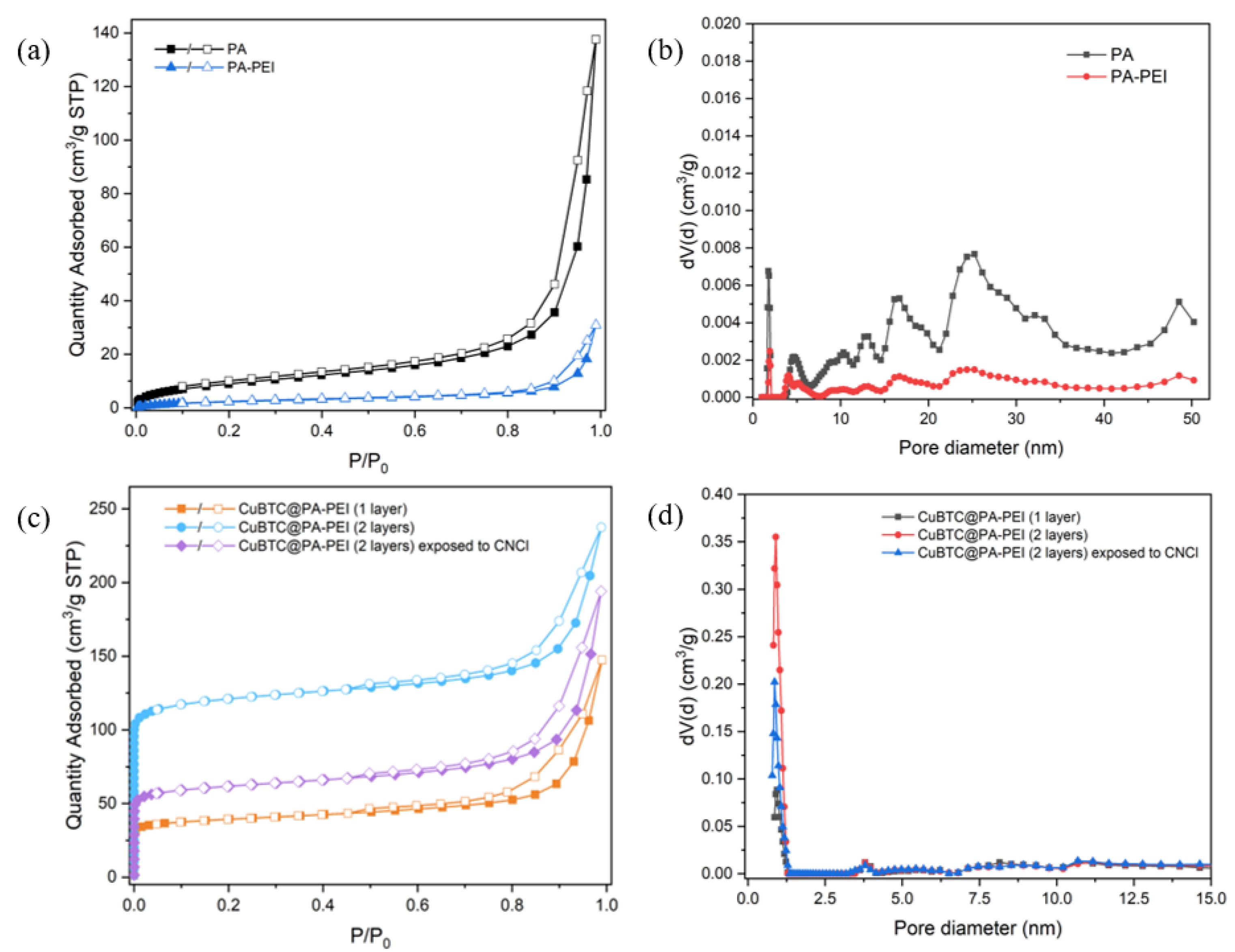
| Sample | SBET (m2/g) |
|---|---|
| PA | 52 |
| PA-PEI | 34 |
| CuBTC@PA-PEI-1 layer | 149 |
| CuBTC@PA-PEI-2 layers (Before) | 471 |
| CuBTC@PA-PEI-2 layers (After) | 236 |
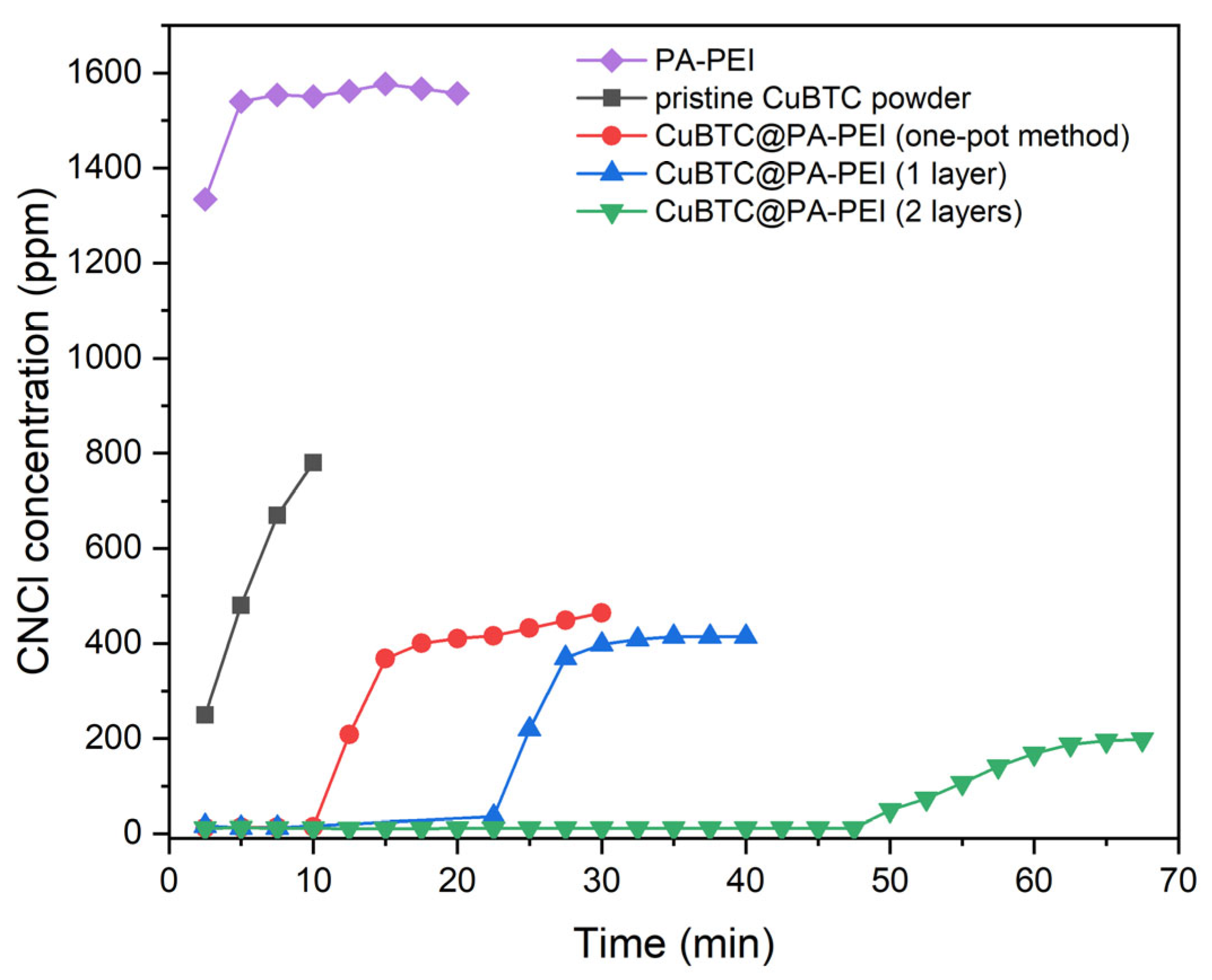
| Sample | Load Rate (%) | Breakthrough Time (min) | CNCl Capacity (mmol·g−1) |
|---|---|---|---|
| CuBTC@PA-PEI (one-pot method) | 16 | 10 | 0.08 |
| CuBTC@PA-PEI (1 layer) | 20 | 22 | 0.18 |
| CuBTC@PA-PEI (2 layers) | 52 | 47 | 0.39 |
| Material Type | Sample | Testing Condition | Breakthrough Time (min) | Ref. |
|---|---|---|---|---|
| Molecular sieve | Cu2+-SiAlMCM-41-TEDA | Challenge concentration: 3200 ppm. Others not mentioned. | 4 | [35] |
| MOF | UiO–66–NH2–5K | Challenge concentration: 1600 ppm. Breakthrough concentration: 2 ppm. Others not mentioned. | 0 | [33] |
| MOF-808 | 0 | [4] | ||
| Activated carbon | Carbon–Cu–Cr–TEDA | 33 | [5] | |
| 10% TEDA/carbon | 0 | [5] | ||
| Metal hydroxide | Zr(OH)4 | 0 | [5] | |
| MOF composite | CuBTC@PA-PEI (2 layers) | 47 | This work |
| Reagent | GMA | TBMA | TMPTA | Toluene | P123 | BPO | Cetyl Alcohol | H2O |
|---|---|---|---|---|---|---|---|---|
| Mass percentage (wt%) | 9.3 | 2.8 | 8.1 | 15.6 | 2.4 | 0.4 | 0.4 | 61 |
| Breakthrough Parameter | Value |
|---|---|
| Challenge concentration | 1600 ppm |
| Temperature | 20 °C |
| Bed weight | 0.7 g |
| Flow rate | 100 mL/min |
Disclaimer/Publisher’s Note: The statements, opinions and data contained in all publications are solely those of the individual author(s) and contributor(s) and not of MDPI and/or the editor(s). MDPI and/or the editor(s) disclaim responsibility for any injury to people or property resulting from any ideas, methods, instructions or products referred to in the content. |
© 2023 by the authors. Licensee MDPI, Basel, Switzerland. This article is an open access article distributed under the terms and conditions of the Creative Commons Attribution (CC BY) license (https://creativecommons.org/licenses/by/4.0/).
Share and Cite
Yang, X.; Lan, L.; Zheng, C.; Kang, K.; Song, H.; Zhou, S.; Bai, S. Fabrication of Hierarchically Porous CuBTC@PA-PEI Composite for High-Efficiency Elimination of Cyanogen Chloride. Molecules 2023, 28, 2440. https://doi.org/10.3390/molecules28062440
Yang X, Lan L, Zheng C, Kang K, Song H, Zhou S, Bai S. Fabrication of Hierarchically Porous CuBTC@PA-PEI Composite for High-Efficiency Elimination of Cyanogen Chloride. Molecules. 2023; 28(6):2440. https://doi.org/10.3390/molecules28062440
Chicago/Turabian StyleYang, Xuanlin, Liang Lan, Chao Zheng, Kai Kang, Hua Song, Shuyuan Zhou, and Shupei Bai. 2023. "Fabrication of Hierarchically Porous CuBTC@PA-PEI Composite for High-Efficiency Elimination of Cyanogen Chloride" Molecules 28, no. 6: 2440. https://doi.org/10.3390/molecules28062440