Article

Flowers Like α-MoO3/CNTs/PANI Nanocomposites as Anode Materials for High-Performance Lithium Storage

by
Laraib Kiran
1,2,3,
Mehmet Kadri Aydınol
3,4,
Awais Ahmad
5,6,
Syed Sakhawat Shah
1,*,
Doruk Bahtiyar
3,4,
Muhammad Imran Shahzad
2,*,
Sayed M. Eldin
7 and
Aboud Ahmed Awadh Bahajjaj
8
1
Chemistry Department, Quaid-i-Azam University, Islamabad 45320, Pakistan
2
Nanosciences and Technology Department (NS&TD), National Centre for Physics (NCP), Islamabad 44000, Pakistan
3
Metallurgical & Materials Engineering Department, Middle East Technical University, Ankara 06800, Turkey
4
ENDAM, Energy Materials and Storage Devices Research Center, Middle East Technical University, Ankara 06800, Turkey
5
Department of Chemistry, University of Lahore, Lahore 54000, Pakistan
6
Departamento de Quimica Organica, Universidad de Cordoba, 14014 Cordoba, Spain
7
Faculty of Engineering and Technology, Future University in Egypt, New Cairo 11835, Egypt
8
Department of Chemistry, College of Science, King Saud University, Riyadh 11451, Saudi Arabia
*
Authors to whom correspondence should be addressed.
Molecules 2023, 28(8), 3319; https://doi.org/10.3390/molecules28083319
Submission received: 20 February 2023 / Revised: 4 April 2023 / Accepted: 4 April 2023 / Published: 8 April 2023

Abstract

:
Lithium-ion batteries (LIBs) have been explored to meet the current energy demands; however, the development of satisfactory anode materials is a bottleneck for the enhancement of the electrochemical performance of LIBs. Molybdenum trioxide (MoO3) is a promising anode material for lithium-ion batteries due to its high theoretical capacity of 1117 mAhg−1 along with low toxicity and cost; however, it suffers from low conductivity and volume expansion, which limits its implementation as the anode. These problems can be overcome by adopting several strategies such as carbon nanomaterial incorporation and polyaniline (PANI) coating. Co-precipitation method was used to synthesize α-MoO3, and multi-walled CNTs (MWCNTs) were introduced into the active material. Moreover, these materials were uniformly coated with PANI using in situ chemical polymerization. The electrochemical performance was evaluated by galvanostatic charge/discharge, cyclic voltammetry (CV) and electrochemical impedance spectroscopy (EIS). XRD analysis revealed the presence of orthorhombic crystal phase in all the synthesized samples. MWCNTs enhanced the conductivity of the active material, reduced volume changes and increased contact area. MoO3-(CNT)12% exhibited high discharge capacities of 1382 mAhg−1 and 961 mAhg−1 at current densities of 50 mAg−1 and 100 mAg−1, respectively. Moreover, PANI coating enhanced cyclic stability, prevented side reactions and increased electronic/ionic transport. The good capacities due to MWCNTS and the good cyclic stability due to PANI make these materials appropriate for application as the anode in LIBs.

1. Introduction

The current fossil fuels-based energy is at a severe risk owing to many factors, including the consumption of non-renewable energy resources. Another worrying aspect of the current fossil fuel energy economy is connected with CO2 emissions, which has increased at a uniform rate, thus resulting in an increased global temperature with a series of sudden climate changes. Environmental pollution and the growing population have caused an energy crisis, therefore it is very difficult to meet the current energy demands. Consequently, researchers are trying to develop affordable, ecofriendly and environment-friendly energy storage devices using low cost, potentially abundant and environment-friendly material. The development of renewable energy technologies is a substantial approach to limit global warming, environmental pollution and the deficiency of fossil-based resources. Energy storage plays a vital role in developing renewable energy systems [1,2,3,4]. Electrochemical systems such as super capacitors and batteries, which can effectively deliver and store energy in power plants, can also provide load levelling and power quality in the integrated systems [5,6].
In this context, lithium-ion batteries (LIBs) have been proved as promising energy storage devices that are widely used in daily life, such as in hybrid electric vehicles, space exploration, aviation [7] and portable electronic devices [8,9,10], owing to high power densities, environmental friendliness, long cycle lives, low self-discharges, high energy densities, small ionic sizes (which permit fast Li+ intercalation in solids) that are a main factor for fast charging, cyclic stabilities, small memory effects and high open circuit voltages [11,12]. To fulfill the current energy demands, the electrochemical performance of LIBs including cycle life, capacity, power density and charging speed should be enhanced [7]. Since the mechanism of LIBs is based on the movement of Li+ ions between the anode and cathode, the electrochemical and physical properties of the electrode materials have significant influence on the performance of the battery; typically, a variety of lithium metal oxides such as LiCoO2 have been used as the cathode material [12], and graphite is mainly used as the anode material in commercial LIBs owing to low cost, stable operational potential and environmental friendliness [13]. However, the graphite anode exhibits poor rate performance owing to a low theoretical capacity of 327 mAhg−1 [10]; it also suffers from lithium dendrite formation, slow ion diffusion coefficient and volume deformation [13]. Moreover, a large hysteresis between lithiation/delithiation causes difficulties in practice applications. Therefore, there is a strong motivation to develop some novel anode materials (an important component of LIBs) with long cycle lives, large capacities and excellent capacity retention [14]. To substitute graphite, transition metal oxide (TMO) anodes, a class of inorganic materials, have been extensively used because of its high theoretical capacity [15,16]. Thus, many transition metal oxides such as Co3O4, CuO, MoO3, WO3, NiO and SnO2 have been prepared. Moreover, Si nanostructures, metal sulfides [17] and tin compounds have also been developed in the field of lithium-ion battery owing to their large theoretical capacities, widespread availability and environmental friendliness [7,18]. Chu et al. prepared MFe2O4@HPSs particles confined with a carbon network that exhibited high cyclic stability and good rate performance. Moreover, these nanoparticles maintain structural integrity during charging and discharging [19]. Qinglin et al. prepared ZnO/ZnFeO4 nanospheres. Impressively, ZnO/ZnFeO4 showed good cycling performance (1137 mAhg−1 after 80 cycles at 1 Ag−1) [20]. Among all of them, transition metal oxides possess variable valence states and diverse morphology [17]. The capacity of a TMO can reach values of 700–1200 mAhg−1. Molybdenum-based materials have been proved as promising electrodes for energy storage systems owing to low cost, multiple valence states and high theoretical capacity [21]. Molybdenum oxide electrodes have been employed as negative and positive electrode materials. Among all of molybdenum oxides, MoO2 and MoO3 are mostly used [21]. To date, MoO3 is used as a promising anode material for Li ion batteries (LIBs) owing to versatile structure, low cost, nontoxicity, natural abundance, adjustable chemical state, high thermal and chemical stability [8], environmental friendliness and a good theoretical capacity of 1117 mAh/g [8], which is three times greater than that of commercial graphite (327 mAh/g) [22]. On the basis of crystallographic arrangement, MoO3 has three different polymorphs, h-MoO3 (hexagonal), metastable [21] β-MoO3 (monoclinic) and α-MoO3 (orthorhombic) [7,23], of which α-MoO3 is the most stable thermodynamically [7,24]. Moreover, MoO6 is a building block of MoO3, and MoO6 octahedron in the layered structure of MoO3 provides a diffusion path for Li ions [23,25,26]. However, α-MoO3 exhibits poor electronic and ionic conductivity and suffers from large volume changes that induce pulverization during delithiation/lithiation, unstable crystal structure, small surface area [21], resulting low specific capacity and poor cycling stability [27,28,29]. During cycling, a major issue with transition metal oxides is pulverization and cracking, which causes aggregation and dispersion in electrode material [12]. In order to cope with these kinds of problems, multiple strategies have been applied to improve electrochemical performance, mechanical strength, surface area, electron and mass transport kinetics and conductivity of TMOs, such as designing nanostructures, introducing conductive agents and engineering defects [21]. MoO3 has been converted into various forms such as nanowires, nanorods, nanobelts [30], nanofibers and nano sheets [24]. The small size of nanoparticles shortens Li+ diffusion path and the large surface area provides active sites [31]. Furthermore, one of the most important approaches to increase electronic conductivity of α-MoO3 and to improve Li+ ion diffusion and electronic conductivity, carbon materials and matrices have been introduced into MoO3 such as carbon nanotubes (CNTs), carbon black (graphene) [32] and polyaniline (PANI).
Moreover, the conducting polymer also provides the conducting backbone, which increases the lithium ion conductivity, stability [33] and electrochemical performance of the electrode [34,35].
Polymer materials such as polypyrrole (Ppy) and polyaniline (PANI) [24] have been coated and the performance has improved. Recently, nanocomposites of MoO3 with poly-pyrrole were synthesized and the nanocomposites exhibited good cycling stability and electrochemical performance in lithium ion batteries, signifying the successful use of the polymer [36]. Polyaniline is considered another polymer for a potential conductive polymer due to its environmental stability, easy synthesis and high conductivity [37]. PANI has a function of improving conductivity and stabilizing the structure. Cai et al. utilized nest-like PANI that reduced volume changes to increase electrochemical performance of Si-based anode materials [37]. Wu et al. prepared a 3D hydrogel conducting network by in situ polymerization that demonstrated good cycling performance [38]. Furthermore, PANI coating on the surface of MoO3 acts as a good anode material for a Li+ ion host.
Moreover, carbon also acts as a buffer that reduces the stress owing to a large volume of expansion during the charging–discharging by enhancing the electrical conductivity of anodes [39,40,41]. Furthermore, carbon increases the structural stability by surrounding the active material particles because it prevents active material aggregation during cycling. However, comparatively, CNTs displayed a good rate capability and cyclic stability over carbon [42].
Conductive carbonaceous materials such as CNTs and reduced graphene oxide (RGO) have been used with MoO3, which can improve conductivity and structural stability, thus increasing the overall electrochemical performance [43]. The unique properties of CNTs such as low density and high conductivity make them well suited to synthesize TMO–CNT nanocomposites for the lithium ion battery. Therefore, we developed a straightforward and facile co-precipitation method for the synthesis of MoO3, MoO3-PANI, MoO3-(CNTs)x% and MoO3-(CNTs)x%-PANI. The battery parameters, such as coulombic efficiency, cyclic stability and capacity retention are compared and discussed with MoO3 bulk.

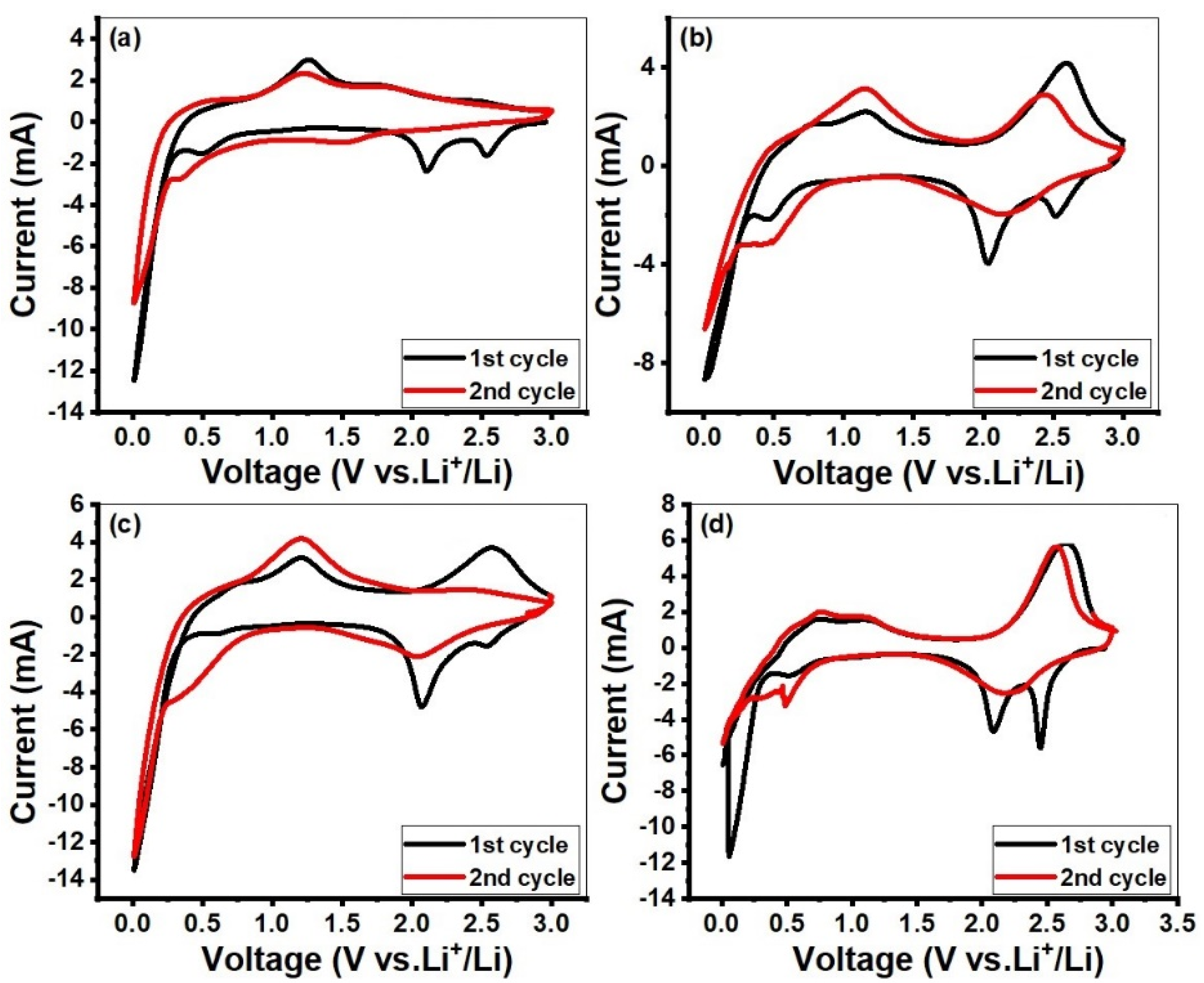
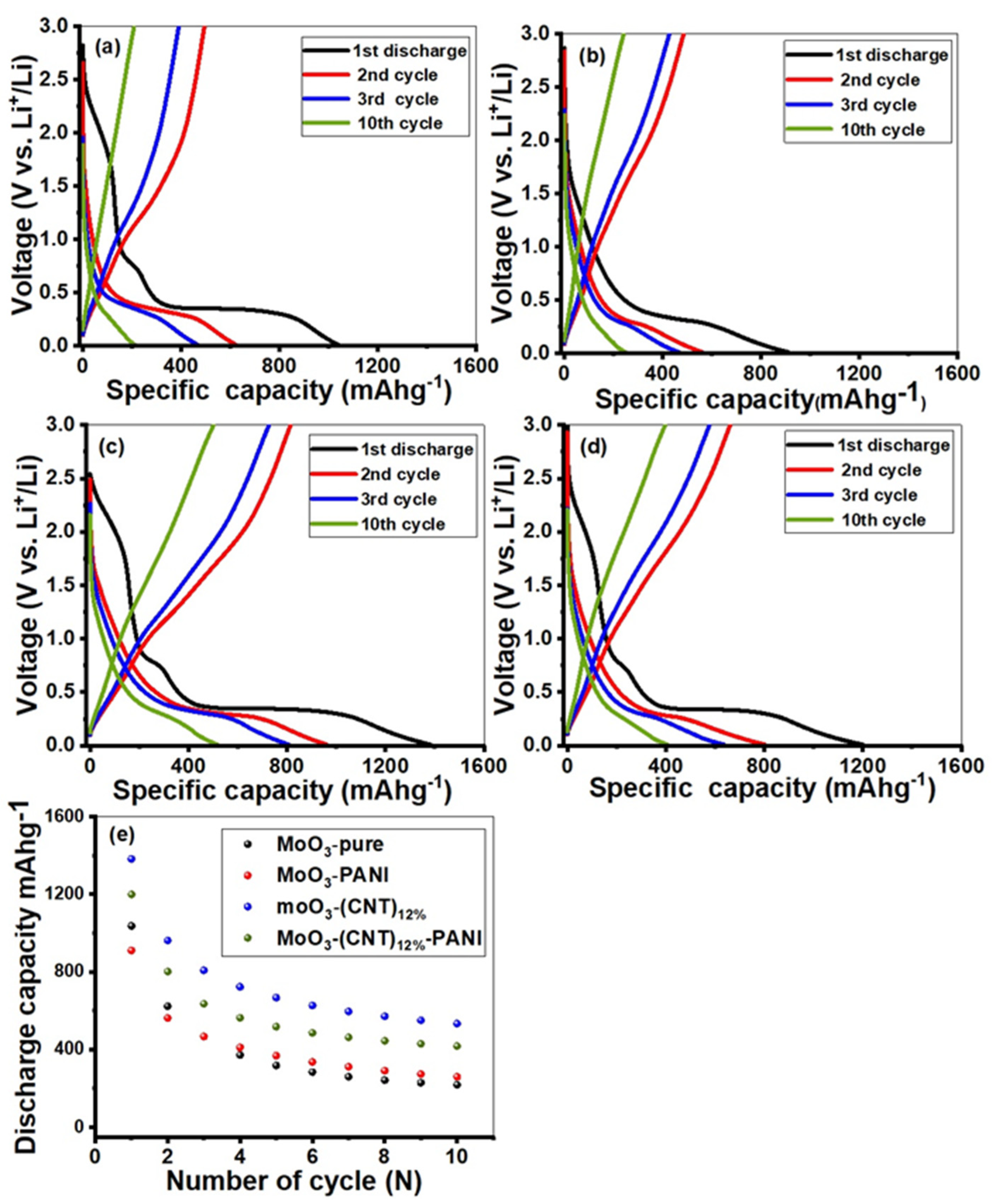
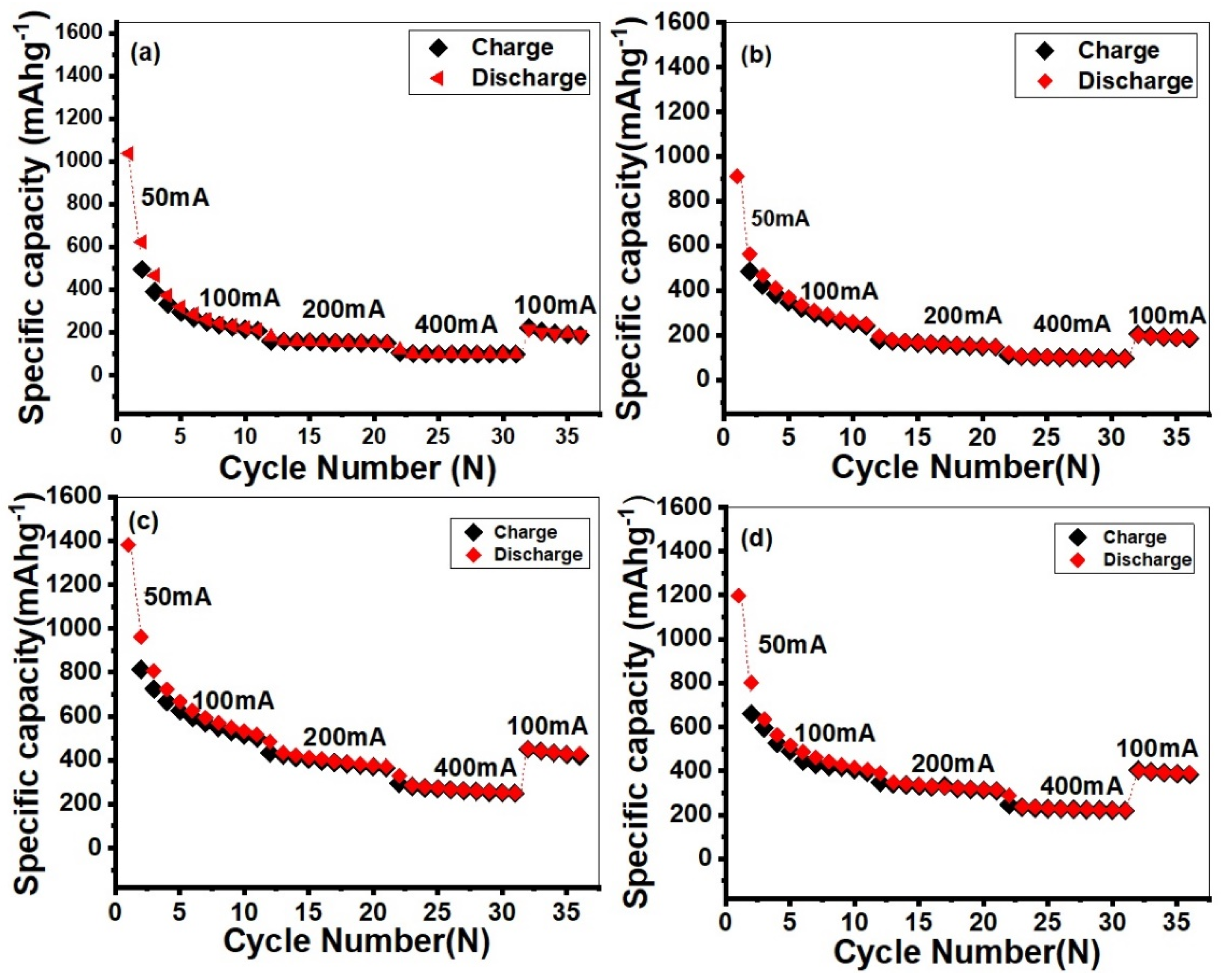
2. Results and Discussion

Figure 1 depicts XRD patterns for MoO3-pure and its nanocomposites, indicating orthorhombic MoO3 phase for all samples with no diffraction peaks of other impurities with the lattice parameters (a = 3.962 Å, b = 13.85 Å, c =3.6970), which are well consistent with the JCPDS card no 05-058 [44,45,46,47]. The three sharp peaks at 23.46, 25.82 and 27.46 can be perfectly indexed to the crystalline orthorhombic phase; however, other minor peaks also showed a best match with the JCPDS card [48]. This observation shows that PANI coating does not affect the crystal lattice of MoO3 and that the structure is preserved. The crystallite sizes for various synthesized samples were calculated using Debye–Scherrer equation as represented: λ is incident wavelength of X-rays, which is 1.5406 nm, β is the full width at half-maximum of the selected peak in radians and θ is the diffraction angle (Bragg’s angle) at which the peak arises and is also measured in radians [49]. The crystallite sizes of the materials are as follows: MoO3 (48.6 nm), MoO3-PANI (41.43 nm), MoO3-(CNT)12% (39.7 nm) and MoO3-(CNT)12%-PANI (47 nm). All information regarding other samples are given in Table S1 (supporting information) and Figure S1.
D = kλ/βcosθ
where D represents crystallite size and k represents the constant usually taken as 0.9. The crystal structure of α-MoO3 is shown at the bottom of Figure 1, in which the red balls represent oxygen and the green balls indicate molybdenum (Mo).
The surface morphologies of the MoO3-pure and their nanocomposites were investigated by SEM. Pure α-MoO3 presented with a uniform plate-like structure that appears like clusters of nanoflowers at low magnification, as shown in Figure 2. At high magnification, it showed a flat smooth surface with a semicircular tip. These plates [50] combined layer by layer to form well oriented microbelts, showing perfect morphology and well crystallinity.
MoO3 maintained a plate-like morphology after the addition of CNTs, but with a small size, unsmooth particle surface and a little disorder, as shown in Figure 3. It was also observed that CNTs were well dispersed around the MoO3 nanoparticles. EDX analysis was also done to determine relative abundance and elemental composition. The corresponding EDS mapping exhibited existence of Mo, O and C.
FTIR (Fourier transform infrared) spectroscopy was employed to investigate the bonding and functional groups of MoO3. FTIR analysis was carried out in the transmittance mode for structure elucidation as well as to assess bonding present between various components, as shown in Figure 4. Two peaks were observed at 565 cm−1 and 678 cm−1, displaying the bending and stretching vibration of MoO [51]. The peaks at 852 cm−1 and 980 cm−1 are assigned to the stretching vibration of the O–Mo–O bond and the stretching vibration of oxygen in Mo–O–Mo, repectively [52]. The small peaks observed at 1471 cm−1 and 1644 cm−1 correspond to the bending vibrations of H–O–H [53]. It also showed the presence of water in crystallization of MoO3.
Pore-size distributions and the nitrogen adsorption–desorption isotherms of MoO3-pure, MoO3-PANI, MoO3-(CNT)12% and MoO3-(CNT)12%-PANI composites are shown in Figure 5. MoO3 showed almost no adsorption at a relative pressure less than 0.9, while it started showing small adsorption when relative pressure approached 1.0. On the contrary, in the case of MoO3-CNTs(12%)-PANI, with the increase of relative pressure, adsorption quantity increased gradually. In addition, in the 0.9–1.0 relative pressure range, hysteresis loop was observed. The BET surface areas of MoO3, MoO3-PANI, MoO3-(CNT)12% and MoO3-(CNT)12%-PANI were 0.849 m2/g, 4.017 m2 g−1, 19.8 m2 g−1 and 41.3 m2 g−1, respectively, and the BJH (Barrett-Joyner-Halenda) pore volumes were 0.0018 cm3g−1, 0.008 cm3g−1, 0.072 cm3g−1 and 0.143 cm3g−1, respectively. MoO3-(CNTs)12%-PANI displayed a broad pore-size distribution in the 5–150 nm pore diameter range. The porous structure with a large surface area makes charge transfer easier at the electrode/electrolyte interface due to additional access points to the electrolyte.
Figure 6 shows the CVs of all the MoO3-based electrodes at the scan rate of 0.5 mVs−1 over a potential range of 0.01–3.0 V for the first two cycles. Three broad peaks were seen at 2.11 V, 2.57 V and 0.01 V vs. Li+/Li in the first cycle of the cathodic polarization process, which corresponds to the lithium intercalation processes, while the current anodic peak at 1.25 V was seen in anodic polarization, which corresponds to the lithium extraction process. More specifically, these types of anodic and cathodic peaks at these potentials represent lithium insertion/de-insertion in different structural sites of MoO3 to form LixMoO3. The strong peak at 0.01 V appeared due to lithiation of MoO3. The area of peak in the first cycle was more than that in the second cycle, which may be attributed to irreversible conversion reactions [54]. The change in the shape of the cathodic peak in the second cycle corresponds to the structural change of the material. When the lithium cation enters into the structure, it increases interlayer spacing and the repulsive forces of the cation leads to cracking of MoO3 and thus decreases the particle size. That is why the peaks of MoO3 change in the next cycles [55,56]. The overall discharge and charge process could be summarized by the Equations (1) and (2) [57]:
Intercalation: MoO3 + xLi+ + xe   →   LixMoO3
Conversion:    LixMoO3 + (6 − x) Li+ + (6 − x) e   ↔    Mo + 3Li2O
Galvanostatic charge/discharge measurements were performed between the voltage windows of 0.01–3 V at a current density of 100 mAg−1, as shown in Figure 7. The initial discharge capacities of MoO3-pure, MoO3 PANI, MoO3-(CNT)12% and MoO3-(CNT)12%-PANI at 100 mAhg−1 were found to be 622.23, 561.75, 961.50 and 801.00 mAhg−1, respectively, while the charge capacities were 494.08, 485.01, 814.04 and 801.00 mAhg−1, respectively and the first coulombic efficiencies were 79.40, 86.30, 84.60 and 82.40%, respectively. All MoO3 anodes led to low coulombic efficiencies in the first cycle, because of large irreversible capacities [55]. The large irreversible capacity arises owing to the following reasons: firstly, the solid electrolyte interface (SEI) formation on the surface of nanoparticles; secondly, decomposition of electrolytes owing to unsaturated carbon atoms. In addition, Li ions may be trapped in the cavities of nanocomposites due to the slow release of Li kinetics, formation of lithium compounds or may be due to the bonding between less coordinated atoms at defect sites [55,58]. From the second discharge onwards, the discharge/charge curves were well coincided. All uncoated samples almost showed similar behavior, showing variations only in the extent to which these materials stored capacity and further how much capacity was retained upon cycling. The first discharge profile showed a rapid potential drop from 3 V until it reached a narrow plateau around 2.3 V, which is due to the intercalation of lithium ions into the crystal structure of the active material, followed by a wide plateau at a potential of 0.8 V, which corresponds to the conversion reaction between lithium ions and molybdenum oxide. Moreover, a steep profile followed this narrow plateau, which tappers off gradually until the potential reached 0.01 V and showed the formation of SEI. The following second discharge curve underwent changes due to the Li+ driven structural changes and therefore did not show any narrow plateau at a potential lower than 2.3 V, followed by a reduction in the wide plateau and steep profile. Information regarding other compositions of α-MoO3 are given in supporting information (Figure S3).
Figure 8 investigates specific capacity, rate performance and cyclic stability of MoO3-pure, MoO3-(CNT)x% and MoO3-(CNT)x%-PANI electrodes at various rates, such as 50 mAg−1, 100 mAg−1, 200 mAg−1 and 400 mAg−1 for 35 cycles. The charge/discharge capacities of Mo-(CNT)12% were 814.5/961.5, 433.8/484.9 and 293.9/330.0 and of MoO3-CNT)12%-PANI nanocomposites were 660.0/801.0, 347.0/390.7, 247.5/286.9 mAg−1 at the current density of 100, 200 and 400 mAg−1, respectively; while pure MoO3 possessed charge/discharge capacities of 494.08/622.23, 160.20/181.40 and 104.10/119.70 at the same current rates, respectively. The graph shows a decrease in capacity with an increase of current density; however, when the current density reduced back to 100 mAg−1, a charge/discharge capacity of 449.93/450.96 and 211/221 in the cases of MoO3-(CNT)12% and pure MoO3, respectively, were obtained and remained stable in the subsequent cycles. PANI occupied some spaces in the nanoparticles, which increased reversibility and cyclic stability owing to the increasing extraction/insertion of the Li+ ion. Carbon nanotubes also improved the performance of the composites because of their conductivity; they also prevented the electrode from disintegrating during charge and discharge. Apart from these, carbon nanotubes were active electrochemically and prevented electrode disintegration by providing a mechanical framework during charge and discharge [59]. On the other hand, carbon nanotubes provided a physical barrier to prevent MoO3 nanoparticles from aggregation and improved structure integrity [60]. Moreover, during cycling, they acted as buffers that accommodate volume changes and thereby maintained structural stability [60]. Specific capacity decreased drastically by increasing the cycle number due to volumetric changes that resulted in a decrease in crystallinity. The stability results of MoO3-(CNT)12% were better compared to those of MoO3-(CNT)12%-PANI (Table 1).
The Nyquist plots of the EIS spectra Z” (ohm) and Z’ (ohm) represent imaginary and real impedance components in the Nyquist plots. To evaluate the kinetics of anode and cathode electrodes and to provide information about the bulk resistance of the electrode, surface film and charge transfer, we measured the electrochemical impedance spectroscopy (EIS) of the MoO3-pure, MoO3-PANI, MoO3-(CNT)12% and MoO3-(CNT)12%-PANI nanocomposite electrodes. An equivalent circuit was employed to model the circuit parameters corresponding to the EIS of the cell. The electrochemical impedance spectra (EIS) of nanocomposites were recorded at an open circuit potential (OCP) as shown in Figure 9. R1 connected in series represents the solution resistance, and the two parallel circuits consisting of constant phase elements (CPEs) and resistance (R) represent the capacitive and resistive load in the cell. R2 and CPE2 denote the resistance and constant phase element of the semicircle obtained at the high frequency region, while R3 and CPE3 are for the semicircle obtained at the low frequency region. According to the literature, the small semicircle in the high frequency region signifies interfacial layers, where Li+ ions migrate through surface films on the electrode encounter resistance. The larger semicircle represents charge transfer resistance and double layer capacitance at the low frequency range. The semicircles, however, are generally depressed and a true capacitor cannot fit well with the experimental data. The CPEs are generally used in place of a capacitor to obtain a better mathematical fit, but their physical justification is not obvious. Heterogeneities in the electrodes, such as surface roughness and porosity, were generally attributed with this observation [63,64]. Physical interpretation of Q and α values in CPE is not straightforward and has no clear physical correspondence. Only alpha (α) can provide a measure of how similar the CPE is to an ideal capacitor. In addition, alpha being close to 0.5 was attributed to the behavior of a porous electrode, whereas for an ideal flat electrode, it is unity. Beyond these, Q and α hardly provide any physical insight and were not analyzed in detail [65].The experimental data (symbols) and the simulated (solid line) data according to the electrical equivalent circuit in the inset of figure are collected in Table 2. The chi-square (χ2) showed an acceptable correlation between simulated and experimental data, thereby validating the equivalent circuit model. At the electrode–electrolyte boundary, there was kinetic resistance offered owing to the charge transfer [66]. MoO3-(CNT)12% showed small resistance due to the electric conductivity offered by CNTs and the small contact resistance of the active material and current collector [67].

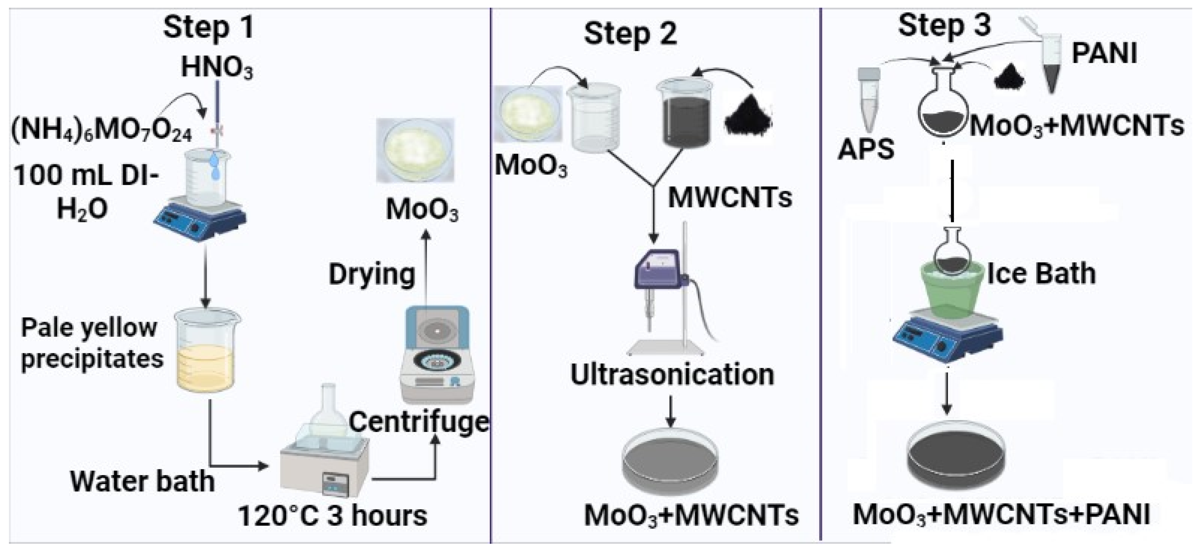
3. Materials and Methods

3.1. Materials

All chemicals and reagents were purchased from Sigma-Aldrich (Saint Louis, MO, USA) and used without any further purifications.

3.2. Synthesis of α-MoO3

MoO3 nanorods were synthesized by adding 0.1 M solution of ammonium heptamolybdate tetrahydrate in 100 mL deionized water, and the solution was stirred continuously for 30 min. Subsequently, 5 mL concentrated nitric acid (HNO3) was poured slowly drop-wise. Pale-yellow colored precipitates were observed in a reaction beaker. The beaker was then placed in a water bath at 120 °C for 3 h. The obtained precipitates were washed, centrifuged and dried for 6 h in an oven at 70 °C.

3.3. Synthesis of α-MoO3-MWCNTs-PANI

Accordingly, for the preparation of MoO3/MWCNTs, (x = 4% (0.15 g), x = 8% (0.312 g), x = 12% (0.48 g)) of functionalized MWCNTS were ultrasonicated for 30 min in 50 mL water (solution A). A quantity of 3.62 g of prepared MoO3 was also ultrasonicated for 30 min in 25 mL water. A total of 25 mL of solution B was transferred to 50 mL of solution A, and the mixture was ultrasonicated for one hour. Excess water was removed using a centrifuge and the remaining was dried in an oven at 50 °C. For the preparation of MoO3/MWCNTs/PANI, an appropriate amount of prepared material was added in a round bottom flask containing 1 M HCl solution and ultrasonicated for half hour, as shown in Figure 10. The solution was then placed in an ice bath, so that during the whole reaction time, the temperature could be maintained. After 10 min of stirring, 10 wt% of aniline monomer was added in a round bottom flask, followed by 30 min of stirring. A calculated amount of ammonium per sulfate (APS) was added in a small amount of distilled water and poured slowly in a round bottom flask. APS acts as an oxidizing agent that mainly initiates polymerization of aniline monomers. The reaction mixture was stirred in an ice bath for 6 h and the temperature was maintained below 4 °C. After 6 h, the mixture was washed many times and dried.

3.4. Physiochemical Characterization

The crystal structure of the sample was investigated by XRD (X-ray diffraction) with Cu kα radiation (λ = 0.154 nm), recorded by Bruker D8 diffractometer. FESEM (field emission scanning electron microscopy) (FEI 430 Nano Scanning Electron Microscope, Ankara, Turkey) was used to confirm the surface morphology. EDX (energy-dispersive X-ray spectroscopy, Turkey) was used for elemental mapping. The pore size distribution and specific surface areas were analyzed by N2 adsorption–desorption isotherm. FTIR (JASCU 6600, NCP, Islamabad, Pakistan) analysis was done to identify the functional groups of MoO3.

3.5. Electrochemical Measurements

Electrochemical measurements were done by using two electrodes and a lithium foil as a reference or counter electrode. The electrode was fabricated by mixing active material, PVDF binder and conductive carbon black in N-methyl-2-pyrrolidinone (NMP) in a weight ratio of (75:15:10). By using the doctor blade, the slurry was evenly pasted on a Cu foil (thickness: 200 μm) and then heated overnight in a vacuum oven. The assembling process was completed in a glovebox under argon (Ar) atmosphere, where concentration of O2 and H2O were below 0.1 ppm. The discharge/charge measurements were done in the voltage range of 0.00–3.0 V at different current densities. CV measurements were performed at a scan rate of 0.5 mVs−1. EIS (electrochemical impedance spectroscopy) was performed at room temperature between the frequency range of 100 kHz and 10 mHZ and an amplitude of 10 mV.

4. Conclusions

The increasing global energy crisis and environmental concerns have stimulated the development of energy storage devices that are efficient and clean for the society. Currently, batteries and SCs have exhibited their potential as energy storage devices, as a consequence of excellent charge–discharge capabilities, their great energy densities and long cycling stabilities. MoO3 electrodes underwent fast growth and their potential in advancement of effective energy storage systems is explained due to their excellent electrochemical performances and good physicochemical properties. However, their low electrical conductivity has retarded their good energy storage application. As a result, to solve this problem, many nanostructured MoO3 and their composites were fabricated. MoO3 and their composites with CNTs and PANI coating proved to have excellent electrochemical performances in batteries and SCs. In this work, MoO3, MoO3-(CNT)x% and MoO3-(CNT)x%-PANI composites with a plate-like morphology, in which MWCNTs were anchored, were synthesized via the co-precipitation method. Various conditions including temperature and acid concentration were optimized to achieve the desired orthorhombic crystal phase. Moreover, these materials were uniformly coated with PANI by in situ chemical polymerization. The morphology and structure of nanocomposites were investigated by scanning electron microscopy (SEM) and X-ray diffraction (XRD), while the specific surface area and porosity were determined using Brunauer-Emmett-Teller (BET) and Barrett-Joyner-Halenda (BJH) methods. Fourier transform-infrared (FTIR) spectrometer analysis was performed in the transmittance mode in the range of 500 to 4000 cm−1 to investigate different functional groups. The electrochemical performance was evaluated by galvanostatic charge/discharge, cyclic voltammetry (CV) and electrochemical impedance spectroscopy (EIS). Pure α-MoO3 and its composites with CNTS were uniformly coated with polyaniline by applying in situ chemical polymerization. The PANI coating layer alleviated volume changes and improved conductivity and cyclic stability. MoO3 with CNTs contributed to fast Li ion diffusion and buffered the volume changes during this work, which further demonstrates the effect of PANI coating on the LiB performance. The CNTs and PANI suppressed aggregation to maintain structural integrity and improved kinetic and conductivity of MoO3. The result showed an increase in specific capacities, particularly in the case of CNT-based composites, where the capacity is recorded as 1382 mAhg−1 at 50 mAhg−1 and 961 at 100 mAhg−1 in the case of MoO3-(CNT)12%. In short, this study suggests strategies of CNT incorporation and polymer coating to address the problems of low electronic and ionic conductivity and the swelling of active materials during cycling that were successful, and in the future, these can be applied to other active materials as well along with changing the morphology from micro to nanoscale.

Supplementary Materials

The following supporting information can be downloaded at: https://www.mdpi.com/article/10.3390/molecules28083319/s1, Figure S1: XRD patterns of nanocomposites; Figure S2: Cyclic voltammograms for all nanocomposites (a) MoO3-(CNTs)4% (b) MoO3-(CNTs)4%-PANI (c) MoO3-(CNTs)(8%) (d) MoO3-(CNTs)8%-PANI nanocomposite; Figure S3: The charge/discharge curves of (a) MoO3-(CNT)4% (b) MoO3-(MWCNT)4%-PANI (c) MoO3-MWCNTS(8%) (d) MoO3-MWCNTs(8%)-PANI of all nanocomposites electrodes (e) Cycling performance of electrodes in the initial 10 cycles; Figure S4: The cyclic performance of (a) MoO3-(CNT)4% (b) MoO3-(CNT)4%-PANI (c) MoO3-(CNTS)8% (d) MoO3-(CNTs)8%-PANI nanocomposite nanocomposites at various current rates; Figure S5: The equivalent circuit and Nyquist plots of MoO3 nanocomposites; Table S1: Crystallite size of nanocomposites; Table S1: EIS fitting results of samples.

Author Contributions

Conceptualization, L.K. and S.S.S.; methodology, A.A.; software, M.K.A.; validation, M.K.A., D.B. and S.S.S.; investigation, M.I.S.; resources, A.A.A.B.; writing—original draft preparation, L.K.; writing—review and editing, A.A.; visualizations, S.M.E.; supervision, S.S.S.; project administration, M.I.S.; funding acquisition, A.A.A.B. All authors have read and agreed to the published version of the manuscript.

Funding

This work was funded by the Researchers Supporting Project Number (RSPD2023R763), King Saud University, Riyadh, Saudi Arabia.

Institutional Review Board Statement

Not applicable.

Informed Consent Statement

Not applicable.

Data Availability Statement

Not applicable.

Acknowledgments

The authors would like to acknowledge the financial support provided by the Türkiye burslari Scholarships/Research Fellowship. This work was funded by the Researchers Supporting Project Number (RSPD2023R763), King Saud University, Riyadh, Saudi Arabia.

Conflicts of Interest

The authors declare that they have no known competing financial interest or personal relationships that could have appeared to influence the work reported in this paper.

Sample Availability

Not applicable.

References

  1. Asen, P.; Shahrokhian, S.; zad, A.I. Ternary nanostructures of Cr2O3/graphene oxide/conducting polymers for supercapacitor application. J. Electroanal. Chem. 2018, 823, 505–516. [Google Scholar] [CrossRef]
  2. Mann, M.E.; Bradley, R.S.; Hughes, M.K. Global-scale temperature patterns and climate forcing over the past six centuries. Nature 1998, 392, 779–787. [Google Scholar] [CrossRef]
  3. Ould Amrouche, S.; Rekioua, D.; Rekioua, T.; Bacha, S. Overview of energy storage in renewable energy systems. Int. J. Hydrogen Energy 2016, 41, 20914–20927. [Google Scholar] [CrossRef]
  4. Bhojane, P.; Shirage, P.M. Facile preparation of hexagonal WO3 nanopillars and its reduced graphene oxide nanocomposites for high-performance supercapacitor. J. Energy Storage 2022, 55, 105649. [Google Scholar] [CrossRef]
  5. Ibrahim, H.; Ilinca, A.; Perron, J. Energy storage systems—Characteristics and comparisons. Renew. Sustain. Energy Rev. 2008, 12, 1221–1250. [Google Scholar] [CrossRef]
  6. Das, C.K.; Bass, O.; Kothapalli, G.; Mahmoud, T.S.; Habibi, D. Overview of energy storage systems in distribution networks: Placement, sizing, operation, and power quality. Renew. Sustain. Energy Rev. 2018, 91, 1205–1230. [Google Scholar] [CrossRef]
  7. Zhu, W.; Kamali, A.R. Green preparation of nanostructured β-MoO3/hexagonal-shaped MoS2/graphene with enhanced lithium-ion storage performance. J. Alloy. Compd. 2023, 932, 167724. [Google Scholar] [CrossRef]
  8. Sheng, D.; Zhang, M.; Wang, X.; Zhou, S.; Fu, S.; Liu, X.; Zhang, Q. Carbon nanotubes embedded in α-MoO3 nanoribbons for enhanced lithium-ion storage. J. Mater. Sci. Mater. Electron. 2022, 33, 11743–11752. [Google Scholar] [CrossRef]
  9. Ding, J.; Sheng, R.; Zhang, Y.; Huang, Y.; Cheng, W.; Liu, Z.; Wang, X.; Guo, Y.; Wang, J.; Jia, D.; et al. Fe2O3/MoO3@NG Heterostructure Enables High Pseudocapacitance and Fast Electrochemical Reaction Kinetics for Lithium-Ion Batteries. ACS Appl. Mater. Interfaces 2022, 14, 37747–37758. [Google Scholar] [CrossRef]
  10. Faizan, M.; Hussain, S.; Islam, M.; Kim, J.Y.; Han, D.; Bae, J.H.; Vikraman, D.; Ali, B.; Abbas, S.; Kim, H.S.; et al. MoO3@MoS2 Core-Shell Structured Hybrid Anode Materials for Lithium-Ion Batteries. Nanomaterials 2022, 12, 2008. [Google Scholar] [CrossRef]
  11. Chen, F.; Wang, J.; Huang, L.; Bao, H.; Shi, Y. Ordered Mesoporous Crystalline Mo-Doped WO2 Materials with High Tap Density as Anode Material for Lithium Ion Batteries. Chem. Mater. 2016, 28, 608–617. [Google Scholar] [CrossRef]
  12. Abbas, S.M.; Ahmad, N.; Ata-ur-Rehman; Rana, U.A.; Khan, S.U.-D.; Hussain, S.; Nam, K.-W. High rate capability and long cycle stability of Cr2O3 anode with CNTs for lithium ion batteries. Electrochim. Acta 2016, 212, 260–269. [Google Scholar] [CrossRef]
  13. Guo, C.; Liu, Z.; Han, K.; Zhang, L.; Ding, X.; Wang, X.; Mai, L. Nano-Sized Niobium Tungsten Oxide Anode for Advanced Fast-Charge Lithium-Ion Batteries. Small 2022, 18, 2107365. [Google Scholar] [CrossRef]
  14. Dong, X.; Zhang, Y.; Cui, C.; Zeng, S.; Fu, C.; Wang, L. Study on the binary transition metal oxide Mn2V2O7 structures for high performance lithium-ion batteries. J. Alloys Compd. 2022, 907, 164518. [Google Scholar] [CrossRef]
  15. Cho, J.S. Large Scale Process for Low Crystalline MoO3-Carbon Composite Microspheres Prepared by One-Step Spray Pyrolysis for Anodes in Lithium-Ion Batteries. Nanomaterials 2019, 9, 539. [Google Scholar] [CrossRef] [Green Version]
  16. Zhong, X.; Huan, H.; Liu, X.; Yu, Y. Facile synthesis of porous germanium-iron bimetal oxide nanowires as anode materials for lithium-ion batteries. Nano Res. 2018, 11, 3702–3709. [Google Scholar] [CrossRef]
  17. Zhu, L.; Han, T.; Ding, Y.; Long, J.; Lin, X.; Liu, J. A metal–organic-framework derived NiFe2O4@NiCo-LDH nanocube as high-performance lithium-ion battery anode under different temperatures. Appl. Surf. Sci. 2022, 599, 153953. [Google Scholar] [CrossRef]
  18. Xiao, Y.; Jiang, M.; Cao, M. Developing WO3 as high-performance anode material for lithium-ion batteries. Mater. Lett. 2021, 285, 129129. [Google Scholar] [CrossRef]
  19. Chu, Y.; Xiong, S. Mixed transition-metal oxides@carbon core-shell nanostructures derived from heterometallic clusters for enhanced lithium storage. Chin. Chem. Lett. 2022, 33, 486–490. [Google Scholar] [CrossRef]
  20. Wang, Q.; Kang, L.; Xing, Z.; Nie, C.; Hong, H.; Zhou, X.; Yun, Q.; Ju, Z.; Chen, B. Prussian Blue Analogue-Derived ZnO/ZnFe2O4 Core-Shell Nanospheres as High-Performance Anodes for Lithium-Ion and Potassium-Ion Batteries. Batter. Supercaps 2022, 6, e202200411. [Google Scholar]
  21. Wang, W.; Xiong, F.; Zhu, S.; Chen, J.; Xie, J.; An, Q. Defect engineering in molybdenum-based electrode materials for energy storage. Escience 2022, 2, 278–294. [Google Scholar] [CrossRef]
  22. Cheng, X.; Li, Y.; Sang, L.; Ma, J.; Shi, H.; Liu, X.; Lu, J.; Zhang, Y. Boosting the electrochemical performance of MoO3 anode for long-life lithium ion batteries: Dominated by an ultrathin TiO2 passivation layer. Electrochim. Acta 2018, 269, 241–249. [Google Scholar] [CrossRef]
  23. Li, Z.; Ma, J.; Zhang, B.; Song, C.; Wang, D. Crystal phase-and morphology-controlled synthesis of MoO3 materials. Crystengcomm 2017, 19, 1479–1485. [Google Scholar] [CrossRef]
  24. Li, J.; Liu, X. Preparation and characterization of α-MoO3 nanobelt and its application in supercapacitor. Mater. Lett. 2013, 112, 39–42. [Google Scholar] [CrossRef]
  25. Ren, H.; Sun, S.; Cui, J.; Li, X. Synthesis, Functional Modifications, and Diversified Applications of Molybdenum Oxides Micro-/Nanocrystals: A Review. Cryst. Growth Des. 2018, 18, 6326–6369. [Google Scholar] [CrossRef]
  26. Tang, K.; Farooqi, S.A.; Wang, X.; Yan, C. Recent Progress on Molybdenum Oxides for Rechargeable Batteries. ChemSusChem 2019, 12, 755–771. [Google Scholar] [CrossRef]
  27. Ding, J.; Abbas, S.A.; Hanmandlu, C.; Lin, L.; Lai, C.-S.; Wang, P.-C.; Li, L.-J.; Chu, C.-W.; Chang, C.-C. Facile synthesis of carbon/MoO3 nanocomposites as stable battery anodes. J. Power Sources 2017, 348, 270–280. [Google Scholar] [CrossRef]
  28. Li, T.; Beidaghi, M.; Xiao, X.; Huang, L.; Hu, Z.; Sun, W.; Chen, X.; Gogotsi, Y.; Zhou, J. Ethanol reduced molybdenum trioxide for Li-ion capacitors. Nano Energy 2016, 26, 100–107. [Google Scholar] [CrossRef] [Green Version]
  29. Li, Y.; Sun, H.; Cheng, X.; Zhang, Y.; Zhao, K. In-situ TEM experiments and first-principles studies on the electrochemical and mechanical behaviors of α-MoO3 in Li-ion batteries. Nano Energy 2016, 27, 95–102. [Google Scholar] [CrossRef] [Green Version]
  30. Cai, L.; Rao, P.M.; Zheng, X. Morphology-controlled flame synthesis of single, branched, and flower-like alpha-MoO3 nanobelt arrays. Nano Lett. 2011, 11, 872–877. [Google Scholar] [CrossRef]
  31. Zhu, J.; Ding, Y.; Ma, Z.; Tang, W.; Chen, X.; Lu, Y. Recent Progress on Nanostructured Transition Metal Oxides As Anode Materials for Lithium-Ion Batteries. J. Electron. Mater. 2022, 51, 3391–3417. [Google Scholar] [CrossRef]
  32. Yan, D.; Luo, X.; Zhang, H.; Zhu, G.; Chen, L.; Chen, G.; Xu, H.; Yu, A. Single-crystalline α-MoO3 microbelts derived from a bio-templating method for superior lithium storage application. J. Alloys Compd. 2016, 688, 481–486. [Google Scholar] [CrossRef]
  33. Yen, J.-Z.; Yang, Y.-C.; Tuan, H.-Y. Interface engineering of high entropy Oxide@Polyaniline heterojunction enables highly stable and excellent lithium ion storage performance. Chem. Eng. J. 2022, 450, 137924. [Google Scholar] [CrossRef]
  34. Yuan, L.; Wang, J.; Chew, S.Y.; Chen, J.; Guo, Z.P.; Zhao, L.; Konstantinov, K.; Liu, H.K. Synthesis and characterization of SnO2–polypyrrole composite for lithium-ion battery. J. Power Sources 2007, 174, 1183–1187. [Google Scholar] [CrossRef]
  35. Bai, Z.; Zhang, Y.; Zhang, Y.; Guo, C.; Tang, B.; Sun, D. MOFs-derived porous Mn2O3 as high-performance anode material for Li-ion battery. J. Mater. Chem. A 2015, 3, 5266–5269. [Google Scholar] [CrossRef]
  36. Li, B.; Li, X.; Li, W.; Wang, Y.; Uchaker, E.; Pei, Y.; Cao, X.; Li, S.; Huang, B.; Cao, G. Mesoporous Tungsten Trioxide Polyaniline Nanocomposite as an Anode Material for High-Performance Lithium-Ion Batteries. Chemnanomat 2016, 2, 281–289. [Google Scholar] [CrossRef]
  37. Cai, J.-J.; Zuo, P.-J.; Cheng, X.-Q.; Xu, Y.-H.; Yin, G.-P. Nano-silicon/polyaniline composite for lithium storage. Electrochem. Commun. 2010, 12, 1572–1575. [Google Scholar] [CrossRef]
  38. Feng, M.; Tian, J.; Xie, H.; Kang, Y.; Shan, Z. Nano-silicon/polyaniline composites with an enhanced reversible capacity as anode materials for lithium ion batteries. J. Solid State Electrochem. 2015, 19, 1773–1782. [Google Scholar] [CrossRef]
  39. Han, F.; Li, D.; Li, W.-C.; Lei, C.; Sun, Q.; Lu, A.-H. Nanoengineered Polypyrrole-Coated Fe2O3@C Multifunctional Composites with an Improved Cycle Stability as Lithium-Ion Anodes. Adv. Funct. Mater. 2013, 23, 1692–1700. [Google Scholar] [CrossRef]
  40. Huang, X.H.; Tu, J.P.; Zhang, C.Q.; Chen, X.T.; Yuan, Y.F.; Wu, H.M. Spherical NiO-C composite for anode material of lithium ion batteries. Electrochim. Acta 2007, 52, 4177–4181. [Google Scholar] [CrossRef]
  41. Jo, M.S.; Ghosh, S.; Jeong, S.M.; Kang, Y.C.; Cho, J.S. Coral-Like Yolk-Shell-Structured Nickel Oxide/Carbon Composite Microspheres for High-Performance Li-Ion Storage Anodes. Nano-Micro Lett. 2019, 11, 3. [Google Scholar] [CrossRef] [PubMed] [Green Version]
  42. Zheng, Y.; Liu, Z.; Liu, B.; Wang, S.; Xiong, C. Fabrication of cactus-like CNT/SiO2/MoO3 ternary composites for superior lithium storage. Energy 2021, 217, 119386. [Google Scholar] [CrossRef]
  43. Lee, H.-J.; Shim, H.-W.; Kim, J.-C.; Kim, D.-W. Mo-MoO3-graphene nanocomposites as anode materials for lithium-ion batteries: Scalable, facile preparation and characterization. Electrochim. Acta 2017, 251, 81–90. [Google Scholar] [CrossRef]
  44. Klinbumrung, A.; Thongtem, T.; Thongtem, S. Characterization of Orthorhombicα-MoO3 Microplates Produced by a Microwave Plasma Process. J. Nanomater. 2012, 2012, 930763. [Google Scholar] [CrossRef] [Green Version]
  45. Saraf, M.; Shuck, C.E.; Norouzi, N.; Matthews, K.; Inman, A.; Zhang, T.; Pomerantseva, E.; Gogotsi, Y. Free-Standing α-MoO MXene Hybrid Electrode in Water-in-Salt Electrolytes. Energy Environ. Mater. 2023, 1, e12516. [Google Scholar] [CrossRef]
  46. Sharma, R.; Sarkar, A.; Jha, R.; Sharma, A.K.; Bhushan, M.; Bhardwaj, R. Synthesis & material properties of α-MoO3 nanoparticles. Mater. Today Proc. 2022, 48, 683–686. [Google Scholar]
  47. Chiang, T.H.; Yeh, H.C. A novel synthesis of α-MoO3 nanobelts and the characterization. J. Alloys Compd. 2014, 585, 535–541. [Google Scholar] [CrossRef]
  48. Jain, V.M.; Shah, D.V.; Patel, K.K.; Doshi, Y. Surfactant free synthesis and characterization of α-MoO3 nanoplates: A feasibility study to remove methylene blue from aqueous medium. IOP Conf. Ser. Mater. Sci. Eng. 2021, 1126, 012052. [Google Scholar] [CrossRef]
  49. Navas, I.; Vinodkumar, R.; Lethy, K.J.; Detty, A.P.; Ganesan, V.; Sathe, V.; Mahadevan Pillai, V.P. Growth and characterization of molybdenum oxide nanorods by RF magnetron sputtering and subsequent annealing. J. Phys. D Appl. Phys. 2009, 42, 175305. [Google Scholar] [CrossRef]
  50. Wu, Z.; Wang, D.; Liang, X.; Sun, A. Ultrasonic-assisted preparation of metastable hexagonal MoO3 nanorods and their transformation to microbelts. Ultrason. Sonochem. 2011, 18, 288–292. [Google Scholar] [CrossRef]
  51. Sen, S.K.; Dutta, S.; Khan, M.R.; Manir, M.S.; Dutta, S.; Al Mortuza, A.; Razia, S.; Hakim, M.A. Characterization and Antibacterial Activity Study of Hydrothermally Synthesized h-MoO3 Nanorods and α-MoO3 Nanoplates. Bionanoscience 2019, 9, 873–882. [Google Scholar] [CrossRef]
  52. Shahsank, M.; Bhojya Naik, H.S.; Sumedha, H.N.; Nagaraju, G. Implementing an in-situ carbon formation of MoO3 nanoparticles for high performance lithium-ion battery. Ceram. Int. 2021, 47, 10261–10267. [Google Scholar] [CrossRef]
  53. Zhou, J.; Lin, N.; Wang, L.; Zhang, K.; Zhu, Y.; Qian, Y. Synthesis of hexagonal MoO3 nanorods and a study of their electrochemical performance as anode materials for lithium-ion batteries. J. Mater. Chem. A 2015, 3, 7463–7468. [Google Scholar] [CrossRef]
  54. Cao, L.; Li, Y.; Wu, J.; Li, W.; Huang, J.; Feng, Y.; Yao, C.; Li, J.; Wang, R.; Kang, Q.; et al. Facile synthesis of carbon coated MoO3 nanorods decorated with WO2 nanoparticles as stable anodes for lithium-ion batteries. J. Alloys Compd. 2018, 744, 672–678. [Google Scholar] [CrossRef]
  55. Liu, C.-L.; Wang, Y.; Zhang, C.; Li, X.-S.; Dong, W.-S. In situ synthesis of α-MoO3/graphene composites as anode materials for lithium ion battery. Mater. Chem. Phys. 2014, 143, 1111–1118. [Google Scholar] [CrossRef]
  56. Besenhard, J.; Heydecke, J.; Fritz, H. Characteristics of molybdenum oxide and chromium oxide cathodes in primary and secondary organic electrolyte lithium batteries I. Morphology, structure and their changes during discharge and cycling. Solid State Ion. 1982, 6, 215–224. [Google Scholar] [CrossRef]
  57. Oh, S.H.; Park, S.M.; Kang, D.-W.; Kang, Y.C.; Cho, J.S. Fibrous network of highly integrated carbon nanotubes/MoO3 composite bundles anchored with MoO3 nanoplates for superior lithium ion battery anodes. J. Ind. Eng. Chem. 2020, 83, 438–448. [Google Scholar] [CrossRef]
  58. Li, M.-Y.; Wang, Y.; Liu, C.-L.; Gao, H.; Dong, W.-S. Iron oxide/carbon microsphere lithium-ion battery electrode with high capacity and good cycling stability. Electrochim. Acta 2012, 67, 187–193. [Google Scholar] [CrossRef]
  59. Tao, T.; Glushenkov, A.M.; Zhang, C.; Zhang, H.; Zhou, D.; Guo, Z.; Liu, H.K.; Chen, Q.; Hu, H.; Chen, Y. MoO3 nanoparticles dispersed uniformly in carbon matrix: A high capacity composite anode for Li-ion batteries. J. Mater. Chem. 2011, 21, 9350. [Google Scholar] [CrossRef]
  60. Liu, Z.; Sun, L.; Yang, W.; Yang, J.; Han, S.; Chen, D.; Liu, Y.; Liu, X. The synergic effects of Na and K co-doping on the crystal structure and electrochemical properties of Li4Ti5O12 as anode material for lithium ion battery. Solid State Sci. 2015, 44, 39–44. [Google Scholar] [CrossRef]
  61. Nadimicherla, R.; Zha, R.; Wei, L.; Guo, X. Single crystalline flowerlike α-MoO3 nanorods and their application as anode material for lithium-ion batteries. J. Alloys Compd. 2016, 687, 79–86. [Google Scholar] [CrossRef]
  62. Francis, M.K.; Bhargav, P.B.; Ramesh, A.; Ahmed, N.; Balaji, C. Electrochemical performance analysis of NiMoO4/α-MoO3 composite as anode material for high capacity lithium-ion batteries. Appl. Phys. A 2022, 128, 132. [Google Scholar] [CrossRef]
  63. Deng, Z.; Zhang, Z.; Lai, Y.; Liu, J.; Li, J.; Liu, Y. Electrochemical Impedance Spectroscopy Study of a Lithium/Sulfur Battery: Modeling and Analysis of Capacity Fading. J. Electrochem. Soc. 2013, 160, A553–A558. [Google Scholar] [CrossRef]
  64. Kim, J.H.; Kwak, E.; Oh, K.Y. Degradation pathways dependency of a lithium iron phosphate battery on temperature and compressive force. Int. J. Energy Res. 2020, 6888–6906. [Google Scholar] [CrossRef]
  65. Mishra, P.; Yavas, D.; Bastawros, A.F.; Hebert, K.R. Electrochemical impedance spectroscopy analysis of corrosion product layer formation on pipeline steel. Electrochimica Acta 2020, 346, 136232. [Google Scholar] [CrossRef]
  66. Xu, C.; Du, H.; Li, B.; Kang, F.; Zeng, Y. Capacitive Behavior and Charge Storage Mechanism of Manganese Dioxide in Aqueous Solution Containing Bivalent Cations. J. Electrochem. Soc. 2009, 156, A73. [Google Scholar] [CrossRef]
  67. Mohan, V.M.; Chen, W.; Murakami, K. Synthesis, structure and electrochemical properties of polyaniline/MoO3 nanobelt composite for lithium battery. Mater. Res. Bull. 2013, 48, 603–608. [Google Scholar] [CrossRef]
Figure 1. XRD patterns of samples and the orthorhombic crystal structure of MoO3.
Molecules 28 03319 g001
Figure 2. FESEM images of MoO3-pure.
Molecules 28 03319 g002
Figure 3. FESEM images of samples (a,b) MoO3-PANI, (c,d) MoO3-(CNT)12% and (e,f) MoO3-(CNT)12%-PANI and (g) EDX spectrum of MoO3.
Molecules 28 03319 g003
Figure 4. FTIR spectrum of the calcined MoO3.
Molecules 28 03319 g004
Figure 5. N2 adsorption/desorption isotherm of MoO3 at 77 K and pore size distribution curve in the inset of the figure.
Molecules 28 03319 g005
Figure 6. Cyclic voltammogram curves of all nanocomposites: (a) MoO3, (b) MoO3-PANI, (c) MoO3-CNTS(12%) and (d) MoO3-CNTs(12%)-PANI nanocomposite.
Molecules 28 03319 g006
Figure 7. The charge/discharge curves of (a) MoO3, (b) MoO3-PANI, (c) MoO3-(CNTS)12% and (d) MoO3-(CNTs)12%-PANI nanocomposite and (e) the cyclic performance of all nanocomposites electrodes in the initial 10 cycles as a function of capacity.
Molecules 28 03319 g007
Figure 8. The cyclic performances of (a) MoO3, (b) MoO3-PANI, (c) MoO3-(CNTS)12% and (d) MoO3-(CNTs)12%-PANI nanocomposites at various current rates.
Molecules 28 03319 g008
Figure 9. Electrochemical impedance spectra of MoO3 electrodes, symbols (experimental data), and solid line (simulated data) at open circuit potential (OCP).
Molecules 28 03319 g009
Figure 10. Schematic diagram of the formation of MoO3-(CNT)x%-PANI composites.
Molecules 28 03319 g010
Table 1. Specific capacities and cycle performances of MoO3-based anodes in LIBs as reported in the literature.
Electrode MaterialInitial Cycle Discharge (mAhg−1)Reversible
Capacity (mAhg−1)
Current Density
(mAg−1)
Ref.
MoO3-(CNT)12%-PANI801406100This Work
MoO3-(CNT)12%961517100This work
α-MoO330118030[61]
α-MoO3211133300[61]
MoO3668157200[52]
MoO3974286100[62]
MoO3-NiMoO41031324100[62]
α-MoO3-CNT583194500[8]
Table 2. EIS fitting results of samples.
NoSamplesR1 (Ω)R2 (Ω)Q2 (Fsα−1)α2R3 (Ω)Q3 (Fsα−1)α3χ2
1MoO37.119.921.21 × 10−30.47412084.39 × 10−30.9040.0077
2MoO3
PANI
2.6620.010.16 × 10−30.64412015.25 × 10−30.8820.00279
3MoO3
(CNT)12%
3.0722.200.11 × 10−30.6783390.01330.7880.00796
4MoO3-(CNT)12%
PANI
5.1645.407.65 × 10−50.7226964.64 × 10−30.7540.00383
Disclaimer/Publisher’s Note: The statements, opinions and data contained in all publications are solely those of the individual author(s) and contributor(s) and not of MDPI and/or the editor(s). MDPI and/or the editor(s) disclaim responsibility for any injury to people or property resulting from any ideas, methods, instructions or products referred to in the content.

