Article

S-Scheme 2D/2D Heterojunction of ZnTiO3 Nanosheets/Bi2WO6 Nanosheets with Enhanced Photoelectrocatalytic Activity for Phenol Wastewater under Visible Light

College of Chemistry & Chemical and Environmental Engineering, Weifang University, Weifang 261000, China
*
Authors to whom correspondence should be addressed.
Molecules 2023, 28(8), 3495; https://doi.org/10.3390/molecules28083495
Submission received: 27 March 2023 / Revised: 12 April 2023 / Accepted: 13 April 2023 / Published: 15 April 2023

Abstract

:
The pollution of phenol wastewater is becoming worse. In this paper, a 2D/2D nanosheet-like ZnTiO3/Bi2WO6 S-Scheme heterojunction was synthesized for the first time through a two-step calcination method and a hydrothermal method. In order to improve the separation efficiency of photogenerated carriers, the S-Scheme heterojunction charge-transfer path was designed and constructed, the photoelectrocatalytic effect of the applied electric field was utilized, and the photoelectric coupling catalytic degradation performance was greatly enhanced. When the applied voltage was +0.5 V, the ZnTiO3/Bi2WO6 molar ratio of 1.5:1 had highest degradation rate under visible light: the degradation rate was 93%, and the kinetic rate was 3.6 times higher than that of pure Bi2WO6. Moreover, the stability of the composite photoelectrocatalyst was excellent: the photoelectrocatalytic degradation rate of the photoelectrocatalyst remained above 90% after five cycles. In addition, through electrochemical analysis, XRD, XPS, TEM, radical trapping experiments, and valence band spectroscopy, we found that the S-scheme heterojunction was constructed between the two semiconductors, which effectively retained the redox ability of the two semiconductors. This provides new insights for the construction of a two-component direct S-scheme heterojunction as well as a feasible new solution for the treatment of phenol wastewater pollution.

1. Introduction

With the development of the phenol industry, the pollution of phenol wastewater has become increasingly serious [1,2]. Traditional phenol wastewater treatment technology easily causes secondary pollution, which limits its application. The emerging photoelectric catalysis technology is valued by the majority of people because of its conformity to the development concept of green and environmental protection [3,4,5]. However, photocatalysts used in phenol wastewater have many problems. For example, TiO2, ZnO, and other materials cannot effectively use sunlight due to their wide band gap and poor response to visible light [6,7,8]. In addition, materials such as CdS and Cu2O are unstable due to their own chemical properties and are easily affected by light corrosion [9,10]. These reasons all limit the application of photocatalytic technology in the degradation of phenol wastewater. Therefore, it is urgent to develop new photocatalytic materials with high visible light response and stable chemical properties suitable for the degradation of phenol wastewater.
Recently, Bi2WO6 has become a research focus because of its layered structure and stable properties. Studies have found that Bi2WO6 has an excellent valence band structure, but the conduction band cannot reduce oxygen to superoxide radicals and the photogenerated carriers are easy to recombine, which reduces the photocatalytic efficiency [11]. For this reason, it is necessary to modify Bi2WO6. To address the problem of photogenerated carrier transfer in traditional heterojunction and Z-scheme heterojunction photocatalysts, Fu et al. proposed the concept of S-scheme (Step-scheme) heterojunction design based on Z-scheme heterojunction without introducing electronic media (redox ion pairs or solid conductors) [12]. The S-scheme heterojunction photocatalyst consists of an oxidation scheme photocatalyst (OP) and a reduction scheme photocatalyst (RP) [13,14]. RP has a higher conduction band, valence band position, and Fermi energy level compared to OP. When RP and OP come into contact, electrons spontaneously transfer from RP to OP until the Fermi energy levels of both reach equilibrium due to the Fermi energy level difference. At this point, a great deal of electrons accumulate at the OP interface, resulting in the energy band bending downward and becoming negatively charged. As electrons are lost at the RP interface, the energy band bends upward and carries a positive charge, eventually forming a built-in electric field from RP to OP [15,16]. After illumination, OP and RP are simultaneously excited to generate photogenerated electrons. Under the synergistic effect of the internal electric field, Coulombic gravity, and band bending, the photogenerated electrons in the OP conduction band are transferred to the RP valence band. Finally, the photogenerated electrons in the RP conduction band and the photogenerated holes in the OP valence band are retained [17,18]. According to the design concept, photogenerated electrons with a weak reduction ability and photogenerated holes with a weak oxidation ability are recombined in S-scheme heterostructures. This improves the separation efficiency of photogenerated electrons and holes, retains photogenerated holes with a strong oxidation ability, and photogenerated electrons with a strong reduction ability, thereby enhancing the oxidation and reduction ability of the catalytic system [19,20]. Bi2WO6 is an excellent oxidized semiconductor due to its strong oxidation capacity of photogenic holes due to the advantage of valence band. The latest research shows that the usage of Bi2WO6 to construct S-scheme heterojunction has an excellent effect in the photocatalytic degradation of pollutants. Li et al. designed and constructed an S-scheme Bi2WO6/CoIn2S4 heterojunction, which greatly enhanced the TC degradation effect [21]. Therefore, it is still a huge challenge to directly construct a two-component S-scheme heterojunction without introducing expensive electron-mediated materials.
In addition, the latest research shows that the conduction band structure of ZnTiO3 is excellent and that the conduction band potential can reduce oxygen to superoxide radicals [22]. Researchers have used ZnTiO3 in the field of photocatalysis and have achieved certain results. Chen et al. found that the ZnTiO3/Zn2Ti3O8/ZnO ternary photocatalyst had an excellent performance in degrading organic pollutants due to its unique S-scheme heterostructure [23]. Lu et al. found that zinc titanate-based heterostructures had an enhanced photocatalytic performance [24]. The ZnTiO3/Zn2Ti3O8/ZnO heterojunction prepared via a simple phase-change method had an excellent performance in hydrogen production and water pollution treatment [25]. According to previous studies, we can see the superiority of the conduction band performance of ZnTiO3. Therefore, ZnTiO3 is an excellent reducing semiconductor. Therefore, the recombination by coupling ZnTiO3 with a high-light electron-generating reduction ability and Bi2WO6 with a high-light hole-generating oxidation ability at the interface to construct an S-scheme heterojunction is expected. The recombination with ZnTiO3 will definitely make up for the conduction band potential of Bi2WO6 not forming •O2, and the interlacing of the two semiconductor band structures can well separate photogenerated electrons and holes. Finally, excellent results have been achieved in the degradation of phenolic pollutants.
The morphologies of the catalysts are varied. Among them, the nanosheet catalyst is more advantageous because the short electron–hole transport path reduces the loss in the transport process and the sheet structure can provide more photoactive sites for photocatalysis to promote the occurrence of the photocatalytic reaction. At present, there are no reports on the work of the S-scheme heterojunction of ZnTiO3/Bi2WO6 in the photocatalytic degradation of phenol wastewater. In this work, a 2D/2D nanosheet ZnTiO3/Bi2WO6 heterojunction system was constructed through the combination of calcining and a hydrothermal method. In addition, the photogenerated carrier was easily recombined during the process of transferring to the catalyst surface for reaction. In order to further improve the separation efficiency of photogenerated carrier, the photoelectric coupling effect of an applied electric field was an effective strategy. The photoelectrochemical performance and photocatalytic performance of the catalyst were studied, and the electron–hole transfer mechanism and functional groups of the photocatalyst were explored. Excellent results were achieved in terms of similar pollutants. This work provides new insights for the construction of a two-component S-scheme heterojunction as well as a feasible new solution for the treatment of phenol wastewater pollution.

2. Results and Discussion

2.1. XRD Analysis

The crystal structure and crystal plane of the sample were characterized by using XRD. Figure 1 shows that the peaks at 28.2°, 32.9°, 47.2°, 56.0°, and 58.5° corresponded to (131), (200), (220), (133), and (107) of Bi2WO6, respectively, according to JCPDS card No. 39-0256. On the crystal plane, compared with the standard card, there was no miscellaneous peak, indicating that the prepared Bi2WO6 had no impurities such as Bi2O3 or WO3 [26]. Figure 1 shows the characteristic peaks of the hexagonal phase ZnTiO3 after hydrothermal calcination. According to JCPDS card No. 39-0190, the diffraction angles of 24.1°, 32.8°, 35.3°, 48.8°, 56.8°, 63.3°, and 68.5° corresponded to the (102), (104), (110), (204), (108), (300), and (208) crystal planes of ZnTiO3, respectively. No impurity peaks such as TiO2 were found, indicating that there was no TiO2 in the prepared ZnTiO3. The diffraction peaks after the two composites became sharp and narrow, indicating that the particle size of the composite catalyst became larger, so the stronger diffraction peaks could be attributed to the increase in the crystallinity of the composite catalyst [27]. In terms of the number of peaks, the diffraction peak of the composite catalyst corresponded to the peak of the single catalyst, indicating that the two semiconductors had successfully combined.

2.2. Morphology Analysis

The morphology of the prepared catalyst can be observed in the SEM images In Figure 2. Figure 2a,b show that the ZnTiO3 was a nanosheet cluster composed of small nanosheets; Figure 2c,d show that the ZnTiO3/Bi2WO6 was composed of large nanosheets attached to small nanosheets. The tightly combined structure of small nanosheets and large nanosheets made the two semiconductors in the ZnTiO3/Bi2WO6 composite catalyst come into close contact to construct countless micro-heterojunctions and improve the utilization of visible light. Figure 2e–i show that the O, W, Bi, Zn, and Ti, respectively, were uniformly distributed, and the overall morphology of the large nanosheets of Bi2WO6 and the cluster shape of the small nanosheets of ZnTiO3 can be observed. The larger Bi2WO6 nanosheet and the smaller ZnTiO3 nanosheet were interleaved and in full contact with each other. The 2D nanosheets with unique morphological advantages could effectively shorten the charge-transfer path and provide a platform for the construction of heterogeneous structures. In order to determine the content of each element in the heterojunction catalyst, EDX tests were carried out; the results are shown in the inset in Figure 2d and in Table 1. The atomic ratio of O, W, Bi, Zn, and Ti was 90.12:2.92:4.93:0.62:1.41.
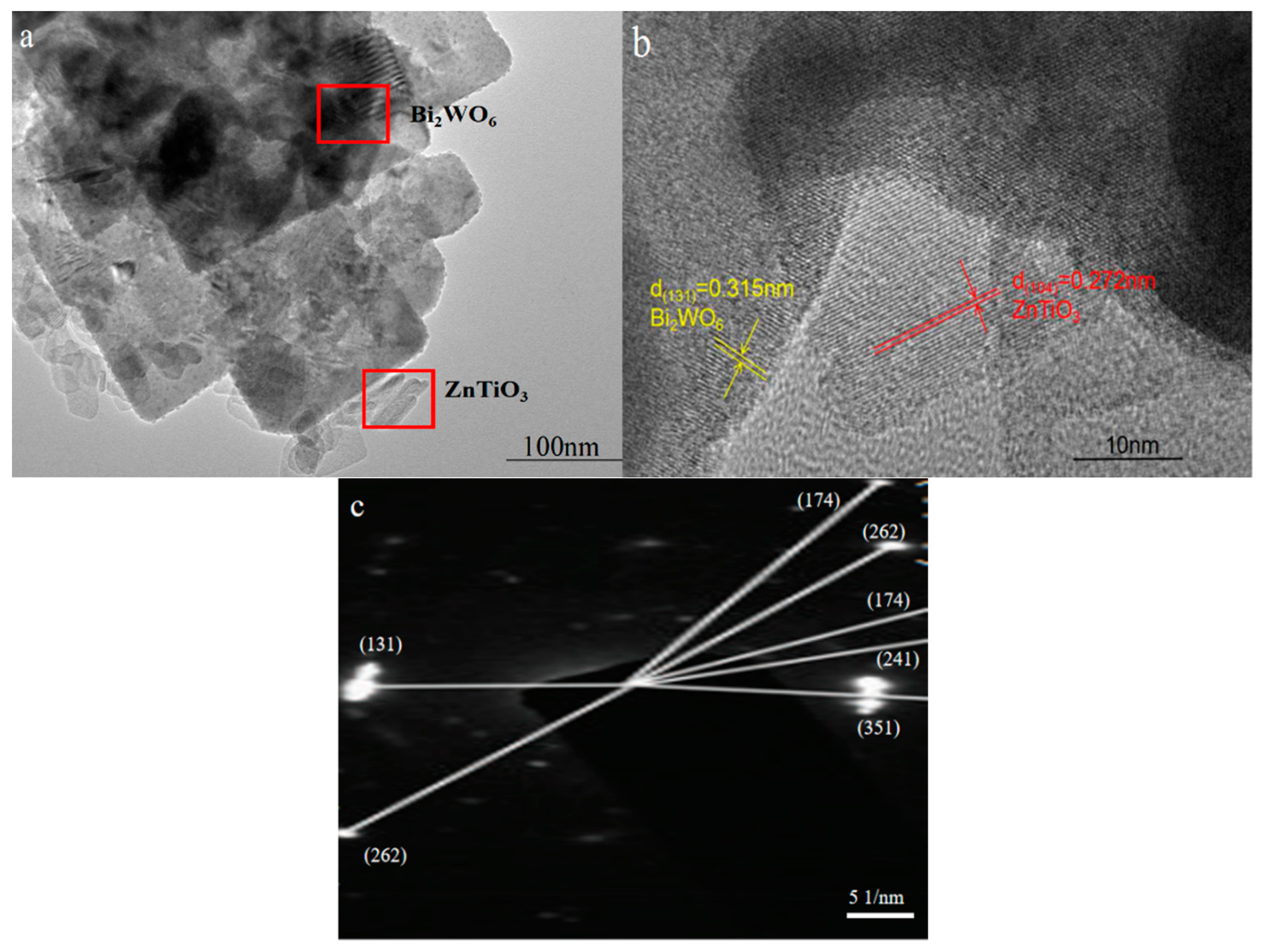
The structure of the sample as shown in the TEM image could not only be analyzed, but the sample also could be qualitative. It can be seen in Figure 3a that the sample was composed of a large square nanosheet connected to small nanosheets, and this morphology was consistent with that observed in the SEM image. It can be seen in Figure 3b that the large nanosheet with a lattice spacing of 0.315 nm corresponded to the spacing of the Bi2WO6 (131) crystal plane [28]. The small nanosheet with a lattice spacing of 0.272 nm was consistent with the (104) crystal plane of ZnTiO3 [29]. It can be seen in Figure 3a,b that the connection of the two sheet-like structures could construct a heterojunction to inhibit the recombination of photogenerated carriers, and only photogenerated holes and electrons could play a redox effect to generate active groups for the photocatalytic degradation process [30]. In addition, the sheet-like structure could shorten the electron–hole transport path, which allowed holes and electrons to quickly reach the surface of the catalyst, and a redox reaction occurred with the H2O and O2 attached to the surface, which activated them into the strong oxidizing free radicals •OH and •O2. At the same time, the sheet-like structure could provide a large surface area so that the organic pollutant molecules and the strong oxidizing free radicals on the surface of the catalyst were oxidized and decomposed into small inorganic molecules [31]. The SAED pattern of the synthesized heterojunction sample is shown in Figure 3c; the crystal patterns of Bi2WO6 were mainly (131), (262), (174), (241), and (351). Among these, (131) was the main exposed crystal plane, which was consistent with the XRD results.

2.3. XPS Analysis

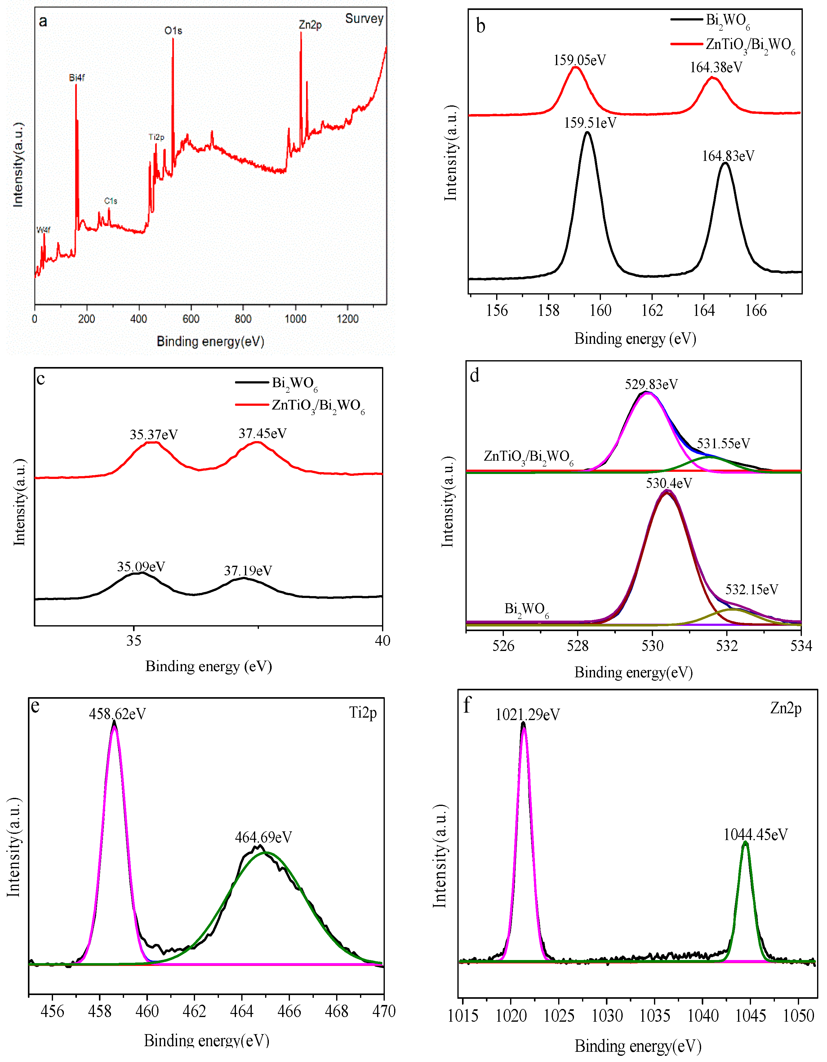
Through XPS characterization, the surface elements and valence state information of the prepared samples were understood. The distribution position of each element can be seen in Figure 4a, indicating that there were Bi, W, O, Ti, and Zn elements in the sample. It can be seen in Figure 4b that 159.05 eV and 164.38 eV corresponded to Bi4f 5/2 and Bi4f 7/2 in the Bi3+ valence state, respectively, which was consistent with a previous study [32].
It can be seen in Figure 4c that 35.37 eV and 37.45 eV corresponded to W4f5/2 and W4f7/2 of the W6+ valence state, respectively, which was consistent with previous studies [33,34]. In the high-resolution spectrum (Figure 4d) of the O element, the characteristic peak of O1s was decomposed into two peaks, and the binding energies of 529.83 eV and 531.55 eV corresponded to the bond energy of O1s lattice oxygen and surface hydroxyl oxygen, respectively. Two peaks could be fitted in the high-resolution spectrum (Figure 4e) of the Ti element. The binding energies of 458.6 eV and 464.5 eV corresponded to Ti2p3/2 and Ti2p1/2, respectively. The difference between the two peaks was 5.9 eV, indicating that Ti in the sample was Ti4+. There were two well-fitted peaks in the high-resolution distribution (Figure 4f). The binding energies of 1021.9 eV and 1045.2 eV corresponded to Zn2p 3/2 and Zn2p 1/2, respectively, indicating that the sample existed in the form of Zn2+ [35]. It can be seen in Figure 4b–d that compared with pure Bi2WO6, the peak of the Bi element in ZnTiO3/Bi2WO6 moved 0.45 eV in the direction of low binding energy, the peak of the W element of ZnTiO3/Bi2WO6 moved 0.28 eV in the direction of high binding energy, and the O element in ZnTiO3/Bi2WO6 moved 0.6 eV in the direction of low binding energy. The shift of binding energy in the XPS spectra was due to the construction of the S-scheme heterojunction between the two semiconductor catalysts. which led to the change in binding energy and the shift in the peak.

2.4. Electrochemical Analysis

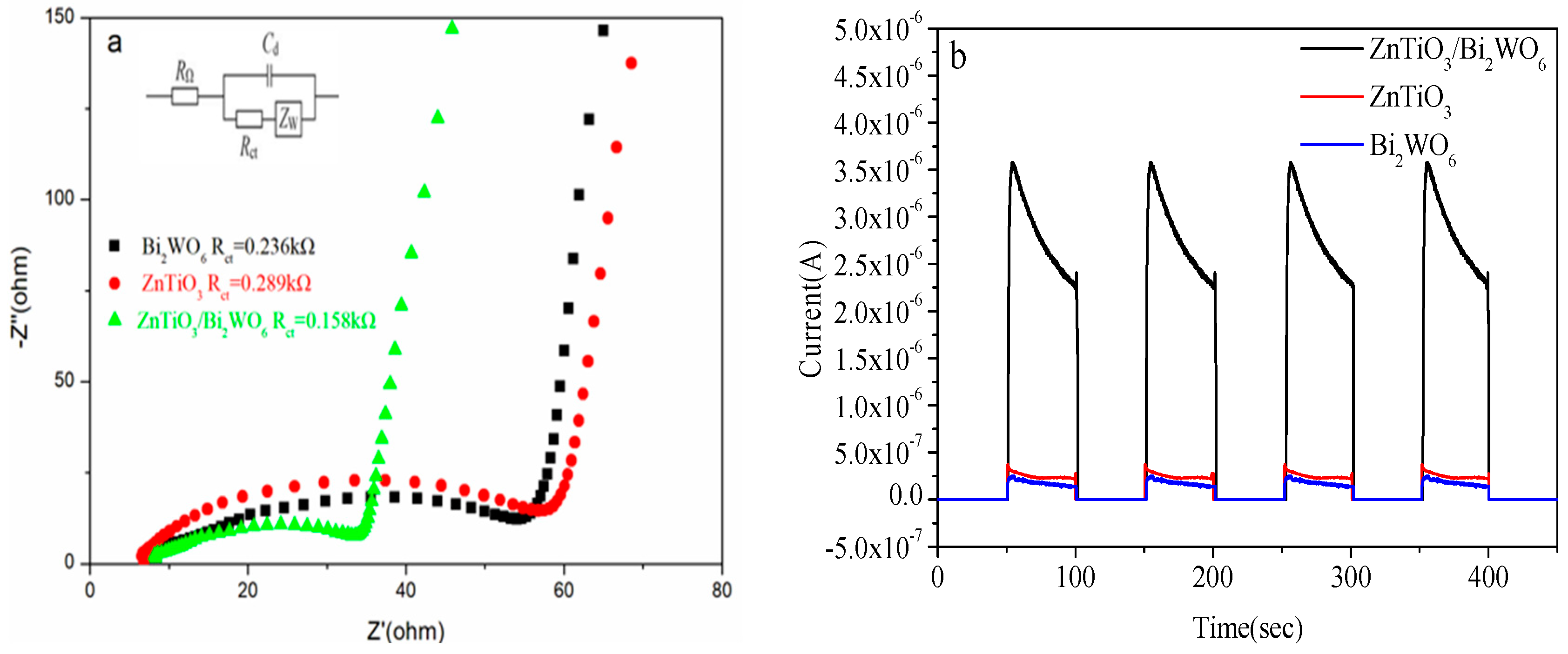
Electrochemical impedance is usually used to detect the rate of charge transfer. The smaller the radius of the arc, the smaller the resistance and the higher the separation efficiency of photogenerated carriers [36]. It can be seen in Figure 5a that the arc radius of ZnTiO3/Bi2WO6 was the smallest. Therefore, the impedance of ZnTiO3/Bi2WO6 was the lowest, the recombination of photogenerated electrons and holes was the smallest, and the photoelectric transmission performance was the best. As shown in Figure 5a, the charge-transfer resistance parameters from the EIS fitting data for the prepared catalysts was tabulated. The charge-transfer resistance parameters of Bi2WO6, ZnTiO3, and Bi2WO6/ZnTiO3 were 0.236 kΩ, 0.289 kΩ, and 0.158 kΩ, respectively. The curvature slope of the impedance curve in the high-frequency range of ZnTiO3/Bi2WO6 was greater than that of Bi2WO6, indicating that the composite catalyst ZnTiO3/Bi2WO6 had a larger capacitance and better electrochemical properties. Transient photocurrent is usually used to prove the transfer efficiency of a light-excited charge and the stability of photogenerated electrons and holes. As shown in Figure 5b, in the experiment of simulating sunlight with four switches, the photocurrent increased and stabilized instantaneously after illumination, which proved that the photogenerated charge carriers of the photocatalyst were relatively stable. The photocurrent was generated by the light-excited photocatalyst to generate electrons and air. Holes and electrons moved through the ITO glass to transmit current to produce a photocurrent curve. The photocurrent intensity of ZnTiO3/Bi2WO6 was 14 times and 12 times that of pure Bi2WO6 and pure ZnTiO3, respectively, indicating that the composite catalyst had a stronger electron transport capacity than a single catalyst, which further proved that the composite photocatalyst had a high electron–hole separation rate. This indicated that the construction of the S-scheme heterojunction accelerated the separation of charge holes and allowed more charges to work to generate a photocurrent. This result was consistent with the previous electrochemical impedance results.

2.5. Photocatalytic Degradation of Phenolic Pollutants

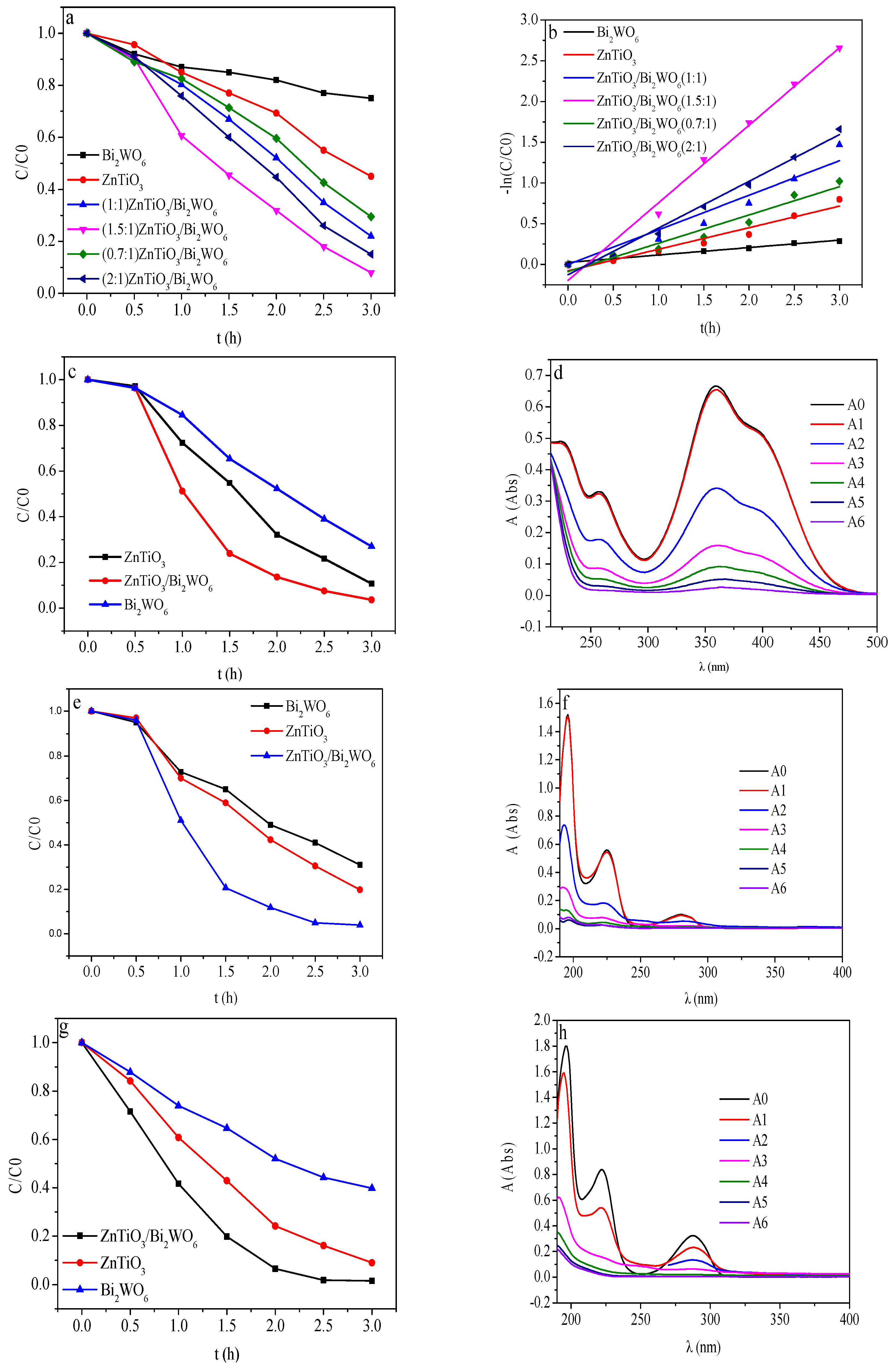
In order to study the performance of the prepared 2D/2D ZnTiO3/Bi2WO6 catalyst, a photoelectrocatalyst degradation experiment was conducted, and the results are shown in Figure 5. When the applied voltage was +0.5 V, there was no electrocatalytic degradation of all kinds of phenolic wastewater in no light, which indicated that the voltage of +0.5 V could not cause electrocatalytic degradation of phenolic wastewater. Therefore, the effect of the applied electric field of +0.5 V was mainly photoelectric coupling, thereby promoting the effective separation of photogenerated electrons and holes. According to Figure 5a and Table 2, by comparing the degradation effects of ZnTiO3/Bi2WO6 with different ratios under the same conditions, we concluded that the molar ratio of 1.5:1 had the best degradation effect; the degradation rate reached 93%. Compared with the pure-phase Bi2WO6 and ZnTiO3 catalysts, the degradation kinetic rate of the composite catalyst for phenol degradation increased by 3.72 times and 2.06 times, respectively. It can be seen in Figure 5b and Table 1 that the composite catalyst with a molar ratio of 1.5:1 had the largest kinetic constant. Compared with the pure Bi2WO6 and ZnTiO3 catalysts, the kinetics of the composite catalyst for degradation of phenol were increased by 3.6 times and 10.42 times, respectively. Compared with the literature, the photocatalytic degradation results in this paper were excellent. The results are shown in Table 3.
Figure 6a shows the phenol degradation effect. Figure 6b shows the kinetic curves of phenol degradation for different molar ratios of ZnTiO3/Bi2WO6. According to Figure 6c–h, based on the photocatalytic experiments on p-nitrophenol, p-chlorophenol, and p-methylphenol, we found that the degradation efficiency of the photoelectrocatalyst for the methoxy electron-donating group was higher than that for the nitro electron-withdrawing group. This was because the electron-withdrawing groups such as nitro and chlorine groups could form conjugated and stable electrons with a benzene ring and the structure was stronger, and the hyperconjugation effect of electron donating groups caused the benzene ring to become strongly activated and easily reactive, so the characteristic group was easy to separate from the benzene ring, and the strong oxidizing group was more likely to attack the benzene ring and degrade phenols [37,38,39].
Table 3. Photocatalytic degradation of phenol wastewater in the presence of semiconductor nanocomposites.
PhotocatalystSynthesis MethodsInitial Pollutant Conc.Light SourceDegradation (%)Ref.
Bi7O9I3/rGOSolvothermal10 mg/L500 W Xe lamp (cutoff filter: λ > 420 nm)78.3[40]
Au/BiOBr/grapheneHydrothermal10 mg/L300 W xenon lamp (cutoff filter: λ > 400 nm)64[41]
Silica nanosheets (SNSs)—supported mixed phaseHydrothermal and post-annealing20 mg/L300 W Xe lamp with a cut-off filter90[42]
GO/SmVO4Sonochemical1.0 × 10−4 mol dm−335 W LED lamp90[43]
TiO2-x/g-C3N4 nanorod arraysUrea drop-calcined and NaBH4 reduction5 ppm300 W Xe lamp87[44]
g-CN@CuOCalcination50 mg/L500 W Xe lamp with a cut-off filter87.8[45]
ZnTiO3/Bi2WO6Hydrothermal10 mg/L350 xenon lamp (λ ≥ 400 nm)93This work
In addition, the most easily oxidized site for phenol and its derivatives was located at the ortho position to the phenolic hydroxyl group. The methyl group was located at the para position of the phenolic hydroxyl group as an electron-donating group, making the ortho position more easily oxidized. The nitro and chlorine groups as electron-withdrawing groups had a passivation effect on the benzene ring, which made the ortho position of the phenolic hydroxyl group more difficult to oxidize. The electron-withdrawing ability of nitro group was stronger than that of chlorine group, so it was more difficult to oxidize.
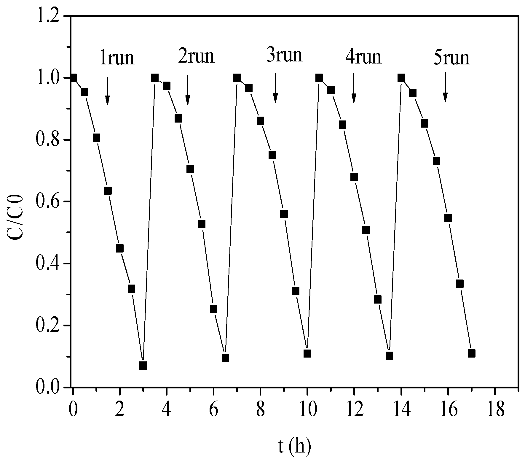
The stability of the photoelectrocatalytic activity of the recovered catalyst was evaluated via cyclic degradation experiments. It can be seen in Figure 7 that the stability of the composite photoelectrocatalyst was excellent. After five cycles, the photoelectrodegradation effect of the photoelectrocatalyst had hardly changed and was still maintained at more than 90%. The high stability of the photoelectrocatalyst also provided the possibility of industrialization of the photoelectrocatalytic treatment of phenolic wastewater [46].
Figure 8a shows that the phenol degradation was intermediate. In Figure 8, the HRMS has been provided for the products after 30, 60, and 90 min of degradation. M/Z = 94 represents phenol; M/Z = 110 represents hydroquinone, catechol, and resorcinol; M/Z = 108 represents p-phenyldiquinone, o-phenyldiquinone, and m-phenyldiquinone; and M/Z = 142 represents maleic acid. After the degradation of phenol, many organic products were produced, among which the main intermediate products were hydroquinone, p-benzoquinone, and maleic acid. The content of maleic acid increased with the longer degradation time. These results indicated that the main path of photocatalytic degradation of phenol was phenol → hydroquinone → -p-benzoquinone → maleic acid.

2.6. Possible Photoelectrocatalytic Mechanism

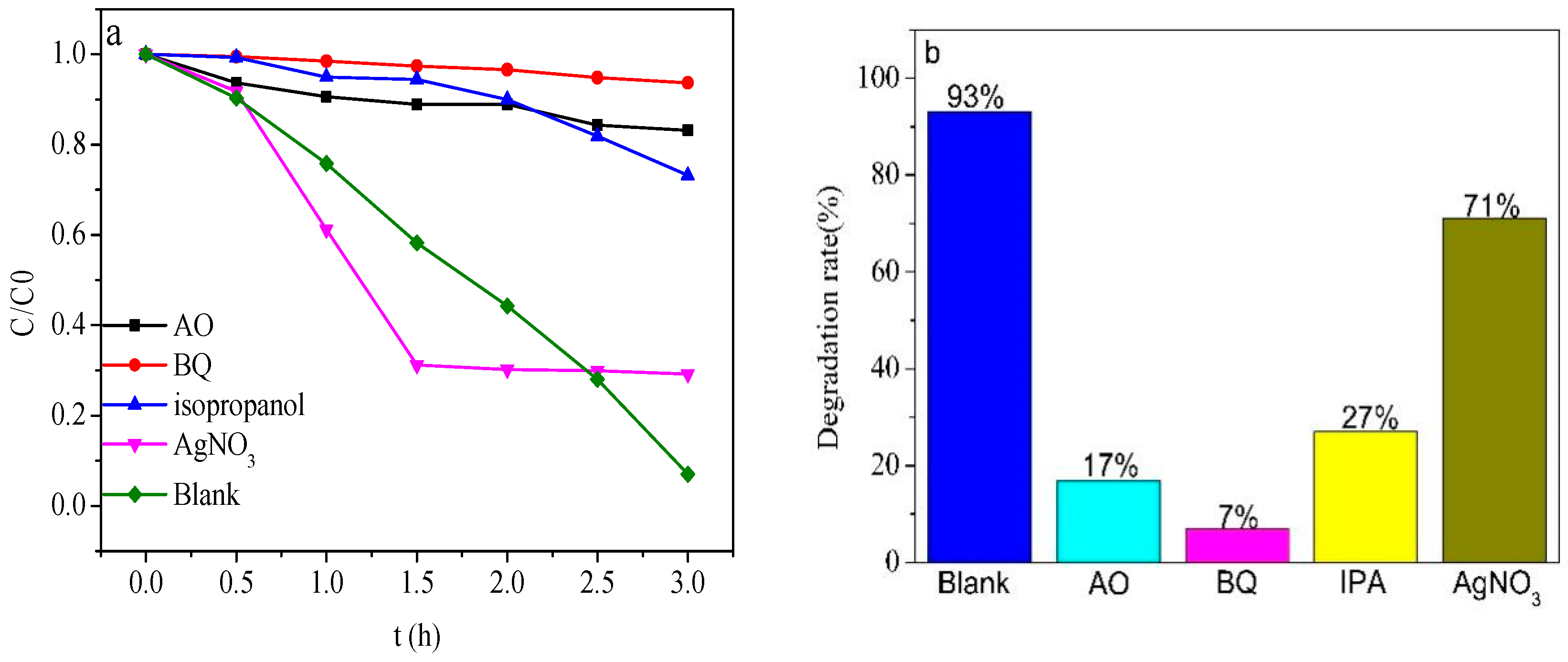
The photoelectrocatalytic mechanism of ZnTiO3/Bi2WO6 under visible light with the applied voltage of +0.5 V was worth pondering. In order to study the mechanism of ZnTiO3/Bi2WO6, free radical-trapping experiments were carried out. We captured •OH with isopropanol(IPA), h+ with ammonium oxalate (AO), •O2 with 1,4-benzoquinone (BQ), and e with AgNO3. The concentration of IPA, TEOA, BQ, and AgNO3 was 1 mM. As shown in Figure 9a,b, after adding BQ and AO, the photocatalytic efficiency decreased from 93% to 7% and 17%, respectively, which indicated that •O2 and h+ were the main active groups. After adding IPA, the photocatalytic efficiency dropped from 93% to 27%, indicating that •OH was the secondary active group.
After adding AgNO3, the photoelectrocatalytic efficiency dropped from 93% to 71%, indicating that e mainly played a supplementary role and was not an active group. After AgNO3 was added, Ag+ combined with e to generate Ag nanoparticles under light conditions, which quenched e. The generated Ag nanoparticles promoted photogenerated electrons and holes due to the local surface plasmon resonance effect when the Ag content was low, which was beneficial to the degradation of phenol, so before 1.5 h, the degradation effect of phenol was better than that of blank. After 1.5 h, the content of Ag nanoparticles was higher than that of the generated Ag nanoparticles, and Ag nanoparticles became new recombination centers of photogenerated electrons and holes, which greatly reduced the degradation effect of phenol.
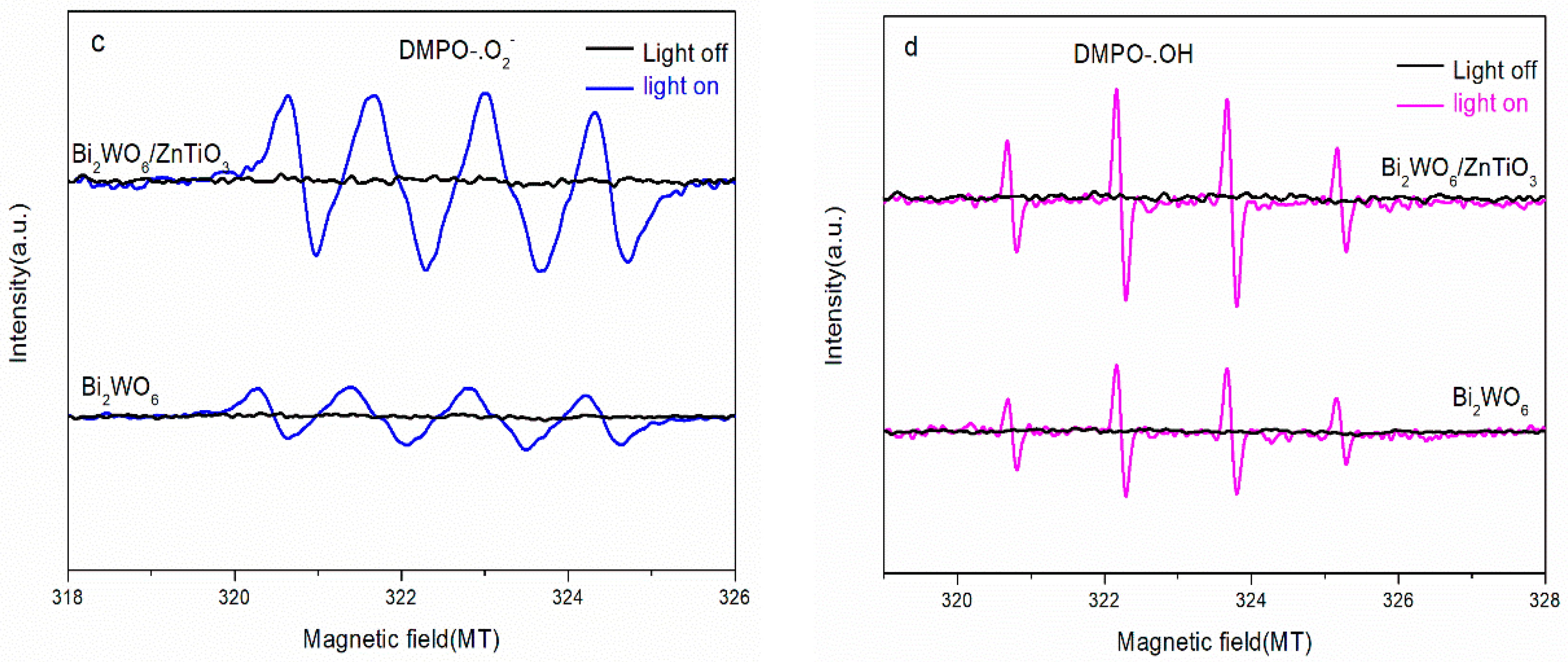
In addition, it can be seen in the ESR spectra in Figure 9c,d that for Bi2WO6/ZnTiO3, the signal of .OH and the signal of .O2 were obviously enhanced, which was consistent with the results of the free radical-capture experiment. This fully proved that the photogenerated carrier separation efficiency of Bi2WO6/ZnTiO3 was significantly improved. The performance of PEC to degrade phenolic wastewater was improved, which was mainly due to the accumulation of h+ and .OH in the valence band of Bi2WO6 and e and .O2 in the conduction band of ZnTiO3. This also indirectly proved the structure of the S-scheme heterojunction in Bi2WO6/ZnTiO3.
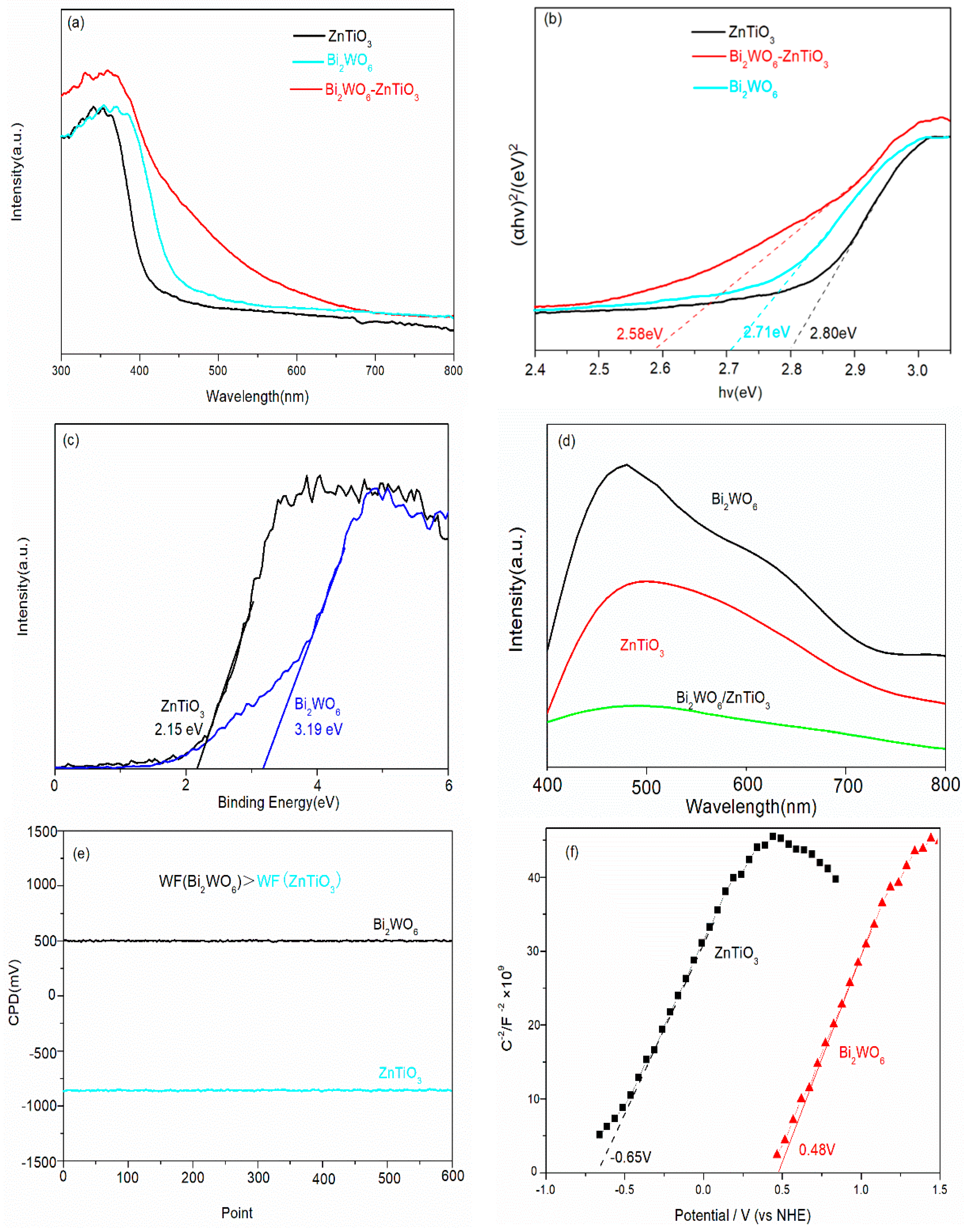
In order to determine the band gap, valence band position, photogenerated carrier separation efficiency, and Fermi level of Bi2WO6, ZnTiO3, and Bi2WO6/ZnTiO3, UV–vis spectroscopy, valence band XPS, PL, and work function tests were performed. The results is shown in Figure 10. According to Figure 10a, the visible light absorption capacity of Bi2WO6/ZnTiO3 after composition was obviously enhanced. Figure 8b shows that the bandgaps of Bi2WO6, ZnTiO3, and Bi2WO6/ZnTiO3 were 2.71 eV, 2.80 eV, and 2.58 eV, respectively. Figure 10c shows the valence band positions of Bi2WO6 and ZnTiO3 at 3.19 eV and 2.15 eV, respectively. Figure 10d shows that the PL spectral signal of Bi2WO6/ZnTiO3 after composition was significantly weakened and that there was no obvious absorption peak, which indicated that the separation efficiency of the photogenerated carrier was significantly improved. The charge-transfer mechanism at the interface of Bi2WO6/ZnTiO3 after recombination may have been the S-scheme heterojunction.
In order to determine the transport direction of photogenerated electrons and holes in the Bi2WO6/ZnTiO3 catalysts, the work functions of Bi2WO6 and ZnTiO3 were measured using a Kelvin probe system (SKP5050, KP Technology Ltd.). The formula was as follows: WF (Sample) = WF (tip) + CPD. Calibration of the WF (tip) was realized with a standard gold sheet (gold, 5.10 eV). CPD was the contact potential difference between the sample and the tip (gold, 5.10 eV). The results are shown in Figure 10e. The work function of Bi2WO6 was 5.60 eV and that of ZnTiO3 was 4.25 eV. Therefore, the Fermi energy level of the work function of Bi2WO6 was significantly lower than that of ZnTiO3. When ZnTiO3 was in contact with Bi2WO6, photogenerated electrons transferred from the conduction band of Bi2WO6 to the valence band of ZnTiO3 for quenching. In addition, the flat band potentials of the photocatalysts is reported according to the Mott–Schottky test. As shown in Figure 10f, the flat band potential of ZnTiO3 was −0.65 V, and the flat band potential of Bi2WO6 was 0.48 V. Photogenerated holes accumulated in the valence band of Bi2WO6 with a stronger oxidation capacity, and photogenerated electrons accumulated in the conduction band of ZnTiO3 with a stronger reduction capacity, forming an S-scheme heterojunction charge-transfer mechanism at the interface.
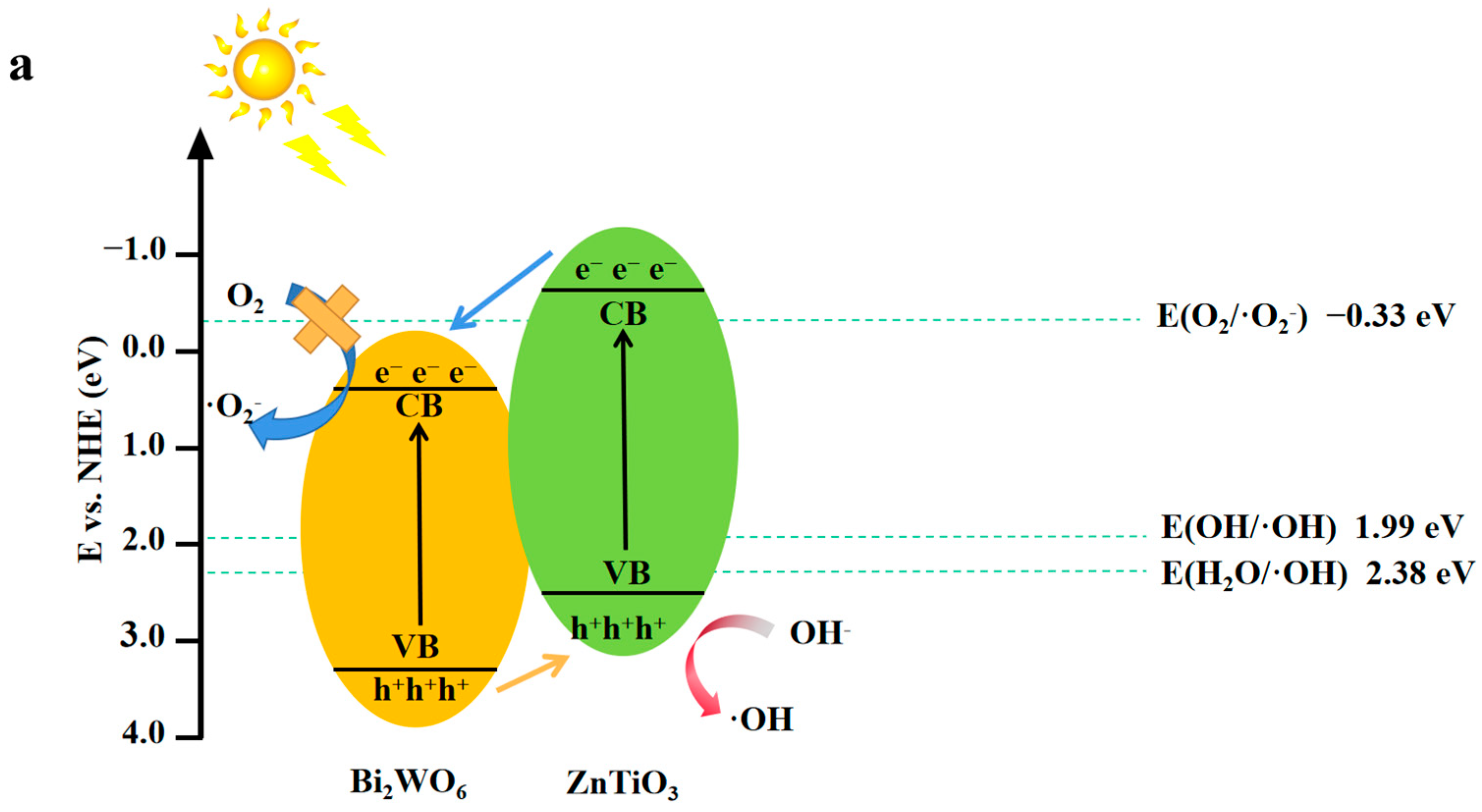
According to the experimental and characterization results, Figure 11 shows the electron–hole transfer pathway and the photoelectrocatalytic mechanism on the ZnTiO3/Bi2WO6 heterojunction. Under visible light irradiation, electrons were excited from the valence band (VB) of Bi2WO6 and ZnTiO3 to the conduction band (CB). Assuming the photocatalytic mechanism was as shown in Figure 11a, because the VB position of Bi2WO6 was higher than the HOMO position of ZnTiO3, the valence band holes of Bi2WO6 were transferred to the valence band of ZnTiO3 because the CB position of Bi2WO6 was lower than the LUMO position of ZnTiO3. The electrons were transferred to the conduction band of Bi2WO6 [47]. However, because the HOMO potential of ZnTiO3 (2.15 eV) was less than E(H2O/•OH) (2.38 eV), the amount of holes in the HOMO of ZnTiO3 was not enough to oxidize H2O to •OH radicals. Therefore, through the reaction, the holes of ZnTiO3 could not form·•OH radicals [48]. Since the conduction band potential of Bi2WO6 was more positive than the standard redox potential of E(O2/•O2) (−0.33 eV), superoxide radical groups could not be formed, which was inconsistent with the conclusion drawn from the quencher experiment [49]. Assuming that according to the photocatalytic mechanism shown in Figure 8b, the holes of ZnTiO3 were combined with the electrons of Bi2WO6, only the holes of Bi2WO6 and the electrons of ZnTiO3 were retained. Because the lowest unoccupied molecular orbital (LUMO) position of ZnTiO3 was more than E(O2/•O2) (−0.33 eV), the standard redox potential was more negative [50,51]. Therefore, the photoelectrons in ZnTiO3 could easily reduce the O2 adsorbed on the catalyst surface to generate •O2 radicals because the VB position of Bi2WO6 (3.19 eV) was more correct than the standard redox potentials E(OH/•OH) (1.99 eV) and E(H2O/•OH) (2.38 eV). The holes in the VB of Bi2WO6 reacted with water or OH in water to form •OH, •OH, and •O2 radicals, which oxidatively degraded the phenolic macromolecules into small molecular products. This derivation was consistent with the conclusions of the quencher experiment, so the most likely explanation is that the ZnTiO3/Bi2WO6 heterojunction was a direct S-scheme photoelectrocatalytic mechanism. In the direct S-scheme semiconductor, the heterojunction formed by the two semiconductors not only retained the superior oxidation–reduction potential, but also reduced the recombination rate of photogenerated electron–hole pairs. This solution greatly improved the oxidation–reduction ability of the Bi2WO6 photoelectrocatalysis.

3. Experiments

3.1. Materials

Zn(CH3COO)2 (AR) (99%), Bi(NO3)•5H2O (AR) (99.999%), Ti(OC4H9)4 (AR) (99%), and Na2WO4.2H2O (AR) (99.99%) were purchased from China Sinopharm Chemical Reagent Co. Ltd., Shanghai, China; ethanol (AR), CO(NH2)2 (AR) (99.99%), Na2SO4 (AR) (99.99%), and ethylene glycol (AR) (99.99%) were purchased from Tianjin Kemiou Chemical Reagent Company, Tianjin, China; and the deionized water was made in the laboratory.

3.2. Preparation of Bi2WO6 and ZnTiO3

First, 2 mmol of Bi(NO3)3•5H2O and 1 mmol of Na2WO4•2H2O were added to 30 mL of ethylene glycol and ultrasonically dispersed for 10 min. The resulting Na2WO4•2H2O solution was slowly added dropwise to the Bi(NO3)3•5H2O solution and then ultrasonically dispersed for 30 min so the solution was mixed thoroughly. Then, the mixed solution was poured into a 100 mL solvothermal reactor and placed in an oven at 160 °C for heating for 12 h. The prepared product was centrifuged. The lower solid was washed with ethanol and deionized water and dried in a vacuum drying oven at a temperature of 60 °C for 24 h to obtain the prepared Bi2WO6 powder.
The ZnTiO3 with a cluster nanoflake structure was successfully prepared by using a two-step calcination method. First, 8.62 g of Zn(CH3COO)2 and 9.86 g of Ti(OC4H9)4 were dissolved in a 100 mL ethanol solution of 1 mol/L of urea and stirred evenly, and the solution was poured into 200 mL of solvent. The reaction kettle was placed in an oven at 160 °C and heated for 12 h; the molar ratio of the Zn:Ti elements was (1:1). After washing and drying the obtained ZnTiO3 precursor, it was placed into a muffle furnace and calcined at 700° for 3 h and then subjected to secondary heat treatment and calcined at 800° for 5 h to obtain a pure ZnTiO3 powder.

3.3. Preparation of ZnTiO3/Bi2WO6

The ZnTiO3/Bi2WO6 composite photocatalyst was prepared by using a hydrothermal method. First, 2 mmol of Bi(NO3)3.5H2O and 1 mmol of Na2WO4•2H2O were each added to 30 mL of deionized water and stirred for 10 min. Then, the Na2WO4•2H2O solution was slowly added dropwise to the Bi(NO3)3•5H2O solution. This mixed solution was called solution A. The pH of solution A was adjusted to 7 with 0.1 mol/L of NaOH solution and stirred for 30 min. According to the different molar ratio of Zn:Bi, the ZnTiO3 prepared above was added to 10 mL of deionized water and ultrasonicated for 30 min to make the dispersion uniform. This ultrasonic suspension, which was called solution B, was added to solution A, and the mixed solution was transferred to a 100 mL hydrothermal reactor and kept at 160 °C for 12 h. Then, the prepared product was centrifuged. The lower solid was washed with ethanol and deionized water and dried in a vacuum drying oven at 60 °C for 24 h to obtain ZnTiO3/Bi2WO6 photocatalysts with different molar ratios.

3.4. Photoelectrocatalytic Degradation of Phenolic Pollutants

First, 100 mL of 10 mg/L phenol solution, 100 mL of 10 mg/L p-nitrophenol solution, 100 mL of 10 mg/L p-chlorophenol solution, and 100 mL of 10 mg/L 4-methylphenol solution were each selected as a pollutant. The photoelectrocatalytic degradation was carried out with a CHI660E three-electrode system electrochemical workstation. An Ag/AgCl electrode was used as the reference electrode, a Pt electrode was used as the counter electrode, and the photocatalyst-coated ITO conductive glass was used as the working electrode. The preparation process was to first mix 10 mg of catalyst and 5 mL of ethanol solution. The mixed system was ground for 15 min, then a proper amount of supernatant was added to ethanol and diluted for 5 min to uniformity, spin-coated on ITO glass, and dried at 60 °C. The light source was 350 W xenon lamp (λ ≥ 400 nm), the electrolyte solution was a 0.1 mol/L Na2SO4 solution, and the applied voltage was +0.5 V. Then, photocatalyst-coated ITO and 100 mL of 10 mg/L phenolic pollutant solution was dispersed for 30 min to reach the equilibrium of adsorption and desorption of organic pollutants in the dark. We took 4 mL samples every 30 min under the illumination of the 350 W xenon lamp (λ ≥ 400 nm) to centrifuge and separate the supernatant. We calculated the degradation rate as D = (1 − Ct/C0) × 100%. In the above formula, C0 is the concentration of the phenolic solution before degradation, Ct is the concentration of the phenolic solution after different degradation times, and D is the calculated degradation rate.

3.5. Electrochemical Analysis

The electrochemical analysis was carried out with a CHI660E three-electrode system electrochemical workstation. An Ag/AgCl electrode was used as the reference electrode, a Pt electrode was used as the counter electrode, and a photocatalyst-coated ITO conductive glass was used as the working electrode. The preparation process was to first mix the catalyst and ethanol solution. The mixed system was ground for 15 min, then a proper amount of supernatant was added to ethanol and diluted for 5 min to uniformity, spin-coated on ITO glass, and dried at 60 °C. the light source was a 350 W xenon lamp (λ ≥ 400 nm), and the electrolyte solution was 0.1 mol/L of Na2SO4 solution. A short photocurrent density measurement was performed during the ON/OFF cycle at 0 V for 450 s. The frequency range test of electrochemical impedance was 100 kW–0.01 W.

3.6. Characterization

XRD was measured using an X-ray diffractometer, and CuKα radiation (λ = 1.5418 Å) was performed in the range of 2θ = 10–80°. The scanning electron microscopy (SEM) was performed with a JEOL-1600 field emission microscope with an acceleration voltage of 5 kV. Transmission electron microscopy (TEM) was performed with a JEOL-2100 (Japan JEOL) operating at 200 kV. X-ray photoelectron spectroscopy (XPS) was performed with an ESCALab MKII spectrometer with MgKα radiation, and its binding energy position was calibrated as C 1 s = 284.6 eV. The UV–vis DRS spectra of Bi2WO6, ZnTiO3, and Bi2WO6/ZnTiO3 were recorded with an ultraviolet–visible spectrophotometer (UV 2600).

4. Conclusions

  • In this paper, 2D/2D heterojunctions of ZnTiO3 nanosheets/Bi2WO6 nanosheets were prepared for the first time by combining a hydrothermal method and a two-step calcination method, and two types of phenolic pollutants were selected. The effects of photocatalysts on electron-absorbing and electron-donating phenolic pollutants were discussed. It was confirmed that the photocatalyst had an obvious degradation effect on the electron-donating phenolic pollutants. This was because the electron-donating group could accelerate the oxidation of the ortho hydroxyl, making the benzene ring easier to decompose.
  • Compared with pure Bi2WO6 (25%), the degradation rate of phenol by the ZnTiO3/Bi2WO6 photocatalyst could reach 93%, and the kinetic rate was increased by 3.6 times. The main reasons for the performance improvement were as follows: (1) 2D/2D ZnTiO3/Bi2WO6 heterojunction shortened the charge-transfer path and reduced the resistance of photogenerated electrons and holes to the surface; (2) the S-scheme heterojunction mechanism was constructed at the ZnTiO3/Bi2WO6 interface, which maintained a higher oxidation potential and reduction potential and realized the spatial separation of photogenerated carriers; and (3) the photoelectric coupling effect of the applied electric field further promoted the separation of the photogenerated carrier and improved the active free radical·OH and·O2. This work provides a new strategy for the degradation of phenolic wastewater.

Author Contributions

C.Z.: Conceptualization, Methodology, Software, Investigation, Writing—original draft; X.T.: Writing—review and editing; Z.J.: Supervision, Data curation; M.L.: Methodology, Validation, Formal analysis, Visualization; J.J.: Supervision, Data curation, Funding, acquisition; Supervision; Q.S.: Methodology, Validation, Formal analysis, Visualization; X.Y.: Supervision, Data curation. All authors have read and agreed to the published version of the manuscript.

Funding

Support for carrying out this work was provided by Shandong Provincial Natural Science (ZR2021QB214) and the Doctoral Research Foundation of Weifang University (2022BS13 and 2021BS48).

Institutional Review Board Statement

Not applicable.

Informed Consent Statement

Not applicable.

Data Availability Statement

Not applicable.

Conflicts of Interest

The authors declare no conflict of interest.

References

  1. Antony, R.P.; Mathews, T. Kinetics of dye destruction using electrochemically synthesized sunlight active N-doped and C and N Co-doped TiO2 nanotubular photocatalysts, Energy Environ. Focus 2013, 2, 139–148. [Google Scholar]
  2. Ochiai, T.; Fujishima, A. Photoelectrochemical properties of TiO2 photocatalyst and its applications for environmental purification. J. Photochem. Photobiol. C 2012, 13, 247–262. [Google Scholar] [CrossRef]
  3. Zhang, H.; Lv, X. P25-Graphene Composite as a High Performance Photocatalyst. ACS Nano 2010, 4, 380–386. [Google Scholar] [CrossRef]
  4. Zhou, W.; Fu, H. ChemInform Abstract: Mesoporous TiO2: Preparation, Doping, and as a Composite for Photocatalysis. ChemCatChem 2013, 5, 885–894. [Google Scholar] [CrossRef]
  5. Hou, Y.; Li, X. Photoeletrocatalytic activity of a Cu2O loaded self-organized highly oriented TiO2 nanotube array electrode for 4-chlorophenol degradation. Environ. Sci. Technol. 2009, 43, 858–863. [Google Scholar] [CrossRef]
  6. Chen, X.; Liu, L.; Yu, P.Y.; Mao, S.S. Increasing Solar Absorption for Photocatalysis with Black Hydrogenated Titanium Dioxide Nanocrystals. Science 2011, 331, 746–750. [Google Scholar] [CrossRef]
  7. Luo, J.M.; Dong, G.; Zhu, Y. Switching of semiconducting behavior from n-type to p-type induced high photocatalytic NO removal activity in g-C3N4. Appl. Catal. B Environ. 2017, 214, 46–56. [Google Scholar] [CrossRef]
  8. Deng, F.; Zhang, Q.; Yang, L. Visible-light-responsive graphene-functionalized Bi-bridge Z-scheme black BiOCl/Bi2O3 heterojunction with oxygen vacancy and multiple charge transfer channels for effificient photocatalytic degradation of 2-nitrophenol and industrial wastewater treatment. Appl. Catal. B Environ. 2018, 238, 61–69. [Google Scholar] [CrossRef]
  9. Tada, H.; Mitsui, T.; Kiyonaga, T.; Akita, T.; Tanaka, K. All-solid-state Z-scheme in CdS-Au-TiO2 three-component nanojunction system. Nat. Mater. 2006, 5, 782–786. [Google Scholar] [CrossRef]
  10. Zhu, Y.; Xu, D.; Meng, M. Ultrasonic-assisted synthesis of amorphous Bi2S3 coupled (BiO)2CO3 catalyst with improved visible light-responsive photocatalytic activity. J. Mater. Sci. 2015, 50, 1594–1604. [Google Scholar] [CrossRef]
  11. Meng, X.C.; Li, Z.Z.; Zeng, H.M.; Chen, J.; Zhang, Z.S. MoS2 quantum dots-interspersed Bi2WO6 heterostructures for visible light-induced detoxifification and disinfection. Appl. Catal. B Environ. 2017, 210, 160–172. [Google Scholar] [CrossRef]
  12. Fu, J.W.; Xu, Q.L.; Low, J.X. Ultrathin 2D/2D WO3/g-C3N4 step-scheme H2-production photocatalyst. Appl. Catal. B Environ. 2019, 243, 556–565. [Google Scholar] [CrossRef]
  13. Bao, Y.J.; Song, S.Q.; Yao, G.J. S-Scheme Photocatalytic Systems. Sol. RRL 2021, 5, 2100118. [Google Scholar] [CrossRef]
  14. Zhang, L.Y.; Zhang, J.J.; Yu, H.G. Emerging S-Scheme Photocatalyst. Adv. Mater. 2022, 34, 2107668. [Google Scholar] [CrossRef] [PubMed]
  15. Xu, Q.L.; Zhang, L.Y.; Cheng, B. S-Scheme Heterojunction Photocatalyst. Chem 2020, 6, 1543–1559. [Google Scholar] [CrossRef]
  16. Wang, J.; Wang, G.H.; Cheng, B. Sulfur-doped g-C3N4/TiO2 S-scheme heterojunction photocatalyst for Congo Red photodegradation. Chin. J. Catal. 2021, 42, 56–68. [Google Scholar] [CrossRef]
  17. Chen, R.F.; Zhou, W.; Qu, W.W.; Wang, Y.J. A novel hierarchical nanostructured S-scheme RGO/Bi2MoO6/Bi2WO6 heterojunction: Excellent photocatalytic degradation activity for pollutants. Appl. Surf. Sci. 2022, 588, 152788. [Google Scholar] [CrossRef]
  18. Tang, D.Y.; Xu, D.S.; Luo, Z.P. Highly Dispersion Cu2O QDs Decorated Bi2WO6 S-Scheme Heterojunction for Enhanced Photocatalytic Water Oxidation. Nanomaterials 2022, 12, 2455. [Google Scholar] [CrossRef] [PubMed]
  19. Li, Y.F.; Xia, Z.L.; Yang, Q. Review on g-C3N4-based S-scheme heterojunction photocatalysts. J. Mater. Sci. Technol. 2022, 125, 128–144. [Google Scholar] [CrossRef]
  20. Han, X.X.; Lu, B.J.; Huang, X. Novel p- and n-type S-scheme heterojunction photocatalyst for boosted CO2 photoreduction activity. Appl. Catal. B Environ. 2022, 316, 121587. [Google Scholar] [CrossRef]
  21. Reddy, K.H.; Martha, S.; Parida, K.M. Erratic charge transfer dynamics of Au/ZnTiO3 nanocomposites under UV and visible light irradiation and their related photocatalytic activities. Nanoscale 2018, 10, 18540–18554. [Google Scholar] [CrossRef] [PubMed]
  22. Anwer, H.; Mahmood, A.; Lee, J. Photocatalysts for degradation of dyes in industrial effluents: Opportunities and challenges. Nano Res. 2019, 12, 955–972. [Google Scholar] [CrossRef]
  23. Chen, F.; Yu, C.; Wei, L. Fabrication and characterization of ZnTiO3/Zn2Ti3O8/ZnO ternary photocatalyst for synergetic removal of aqueous organic pollutants and Cr(VI) ions. Sci. Total Environ. 2019, 706, 136026. [Google Scholar] [CrossRef] [PubMed]
  24. Lu, J.; Li, D.; Chai, Y. Rational design and preparation of nanoheterostructures based on zinc titanate for solar-driven photocatalytic conversion of CO2 to valuable fuels. Appl. Catal. B-Environ. 2019, 5, 117800. [Google Scholar] [CrossRef]
  25. Yu, C.; Chen, F.; Zhou, W. A facile phase transformation strategy for fabrication of novel Z-scheme ternary heterojunctions with efficient photocatalytic properties. Nanoscale 2019, 11, 7720–7733. [Google Scholar] [CrossRef] [PubMed]
  26. Huang, J.; Tan, G.; Yang, W. Synthesis and Photocatalytic Properties of N/Bi2WO6 Flower-like Crystallites Self-Assembled from Nanoflflakes. J. Clust. Sci. 2013, 24, 1139–1149. [Google Scholar] [CrossRef]
  27. Chi, Y.; Yuan, Q.; Hou, S.; Zhao, Z. Synthesis and characterization of mesoporous ZnTiO3 rods via a polyvinylpyrrolidone assisted sol–gel method. Ceram. Int. 2016, 42, 5094–5099. [Google Scholar] [CrossRef]
  28. Meng, X.C.; Zhang, Z.S. Synthesis and characterization of plasmonic and magnetically separable Ag/AgCl-Bi2WO6@ Fe3O4@SiO2 core-shell composites for visible light-induced water detoxification. J. Colloid Interface Sci. 2017, 485, 296–307. [Google Scholar] [CrossRef] [PubMed]
  29. Raveendra, R.S.; Prashantha, P.A.; Krishnac, R.H. Synthesis, structural characterization of nano ZnTiO3 ceramic: An effective azo dye adsorbent and antibacterial agent. J. Asian Ceram. Soc. 2014, 2, 357–365. [Google Scholar] [CrossRef] [Green Version]
  30. Hu, J.; Chen, D.; Mo, Z. Z-Scheme 2D/2D Heterojunction of Black Phosphorus/ Monolayer Bi2WO6 Nanosheets with Enhanced Photocatalytic Activities. Angew. Chem. Int. Ed. 2019, 58, 2073–2077. [Google Scholar] [CrossRef]
  31. Xu, J.; Yue, J.; Niu, J. Fabrication of Bi2WO6 quantum dots/ultrathin nanosheets 0D/2D homojunctions with enhanced photocatalytic activity under visible light irradiation. Chin. J. Catal. 2018, 39, 1910–1918. [Google Scholar] [CrossRef]
  32. Zhu, Z.L.; Ren, Y.; Li, Q. One-pot electrodeposition synthesis of Bi2WO6/graphene composites for photocatalytic applications under visible light irradiation. Ceram. Int. 2018, 44, 3511–3516. [Google Scholar] [CrossRef]
  33. Wang, R.S.; Li, B.; Xiao, Y. Optimizing Pd and Au-Pd decorated Bi2WO6 ultrathin nanosheets for photocatalytic selective oxidation of aromatic alcohols. J. Catal. 2018, 364, 154–165. [Google Scholar] [CrossRef]
  34. He, W.; Sun, Y.; Jiang, G. Activation of amorphous Bi2WO6 with synchronous Bi metal and Bi2O3 coupling: Photocatalysis mechanism and reaction pathway. Appl. Catal. B Environ. 2018, 232, 340–347. [Google Scholar] [CrossRef]
  35. Ranjith, K.S.; Uyar, T. Conscientious Design of Zn-S/Ti N Layer by Transformation of ZnTiO3 on Electrospun ZnTiO3@TiO2 Nanofifibers: Stability and Reusable Photocatalytic Performance under Visible Irradiation. ACS Sustain. Chem. Eng. 2018, 6, 12980–12992. [Google Scholar] [CrossRef] [Green Version]
  36. Qian, W.; Greaney, P. Low-Temperature Nitrogen Doping in Ammonia Solution for Production of N-Doped TiO2-Hybridized Graphene as a Highly Efficient Photocatalyst for Water Treatment. ACS Sustain. Chem. Eng. 2014, 2, 1802–1810. [Google Scholar] [CrossRef]
  37. Long, G.Y.; Ding, G.Y. Fabrication of mediator-free g-C3N4/Bi2WO6 Z-scheme with enhanced photocatalytic reduction dechlorination performance of 2,4-DCP. Appl. Surf. Sci. 2018, 455, 1010–1018. [Google Scholar] [CrossRef]
  38. Zhang, Z.; Shen, Q.H.; Cissoko, N. Catalytic dechlorination of 2,4-dichlorophenol by Pd/Fe bimetallic nanoparticles in the presence of humic acid. J. Hazard. Mater. 2010, 182, 252–258. [Google Scholar] [CrossRef] [PubMed]
  39. Arellano-Gonzalez, M.A.; Texier, A.C.; Lartundo-Rojas, L.; Gonzalez, I. Electrochemical dechlorination of 2-chlorophenol on Pd/Ti, Ni/Ti and Pd-Ni Alloy/Ti electrodes. J. Electrochem. Soc. 2015, 162, 223–230. [Google Scholar] [CrossRef] [Green Version]
  40. Gawande, S.B.; Gawande, K.B.; Thakare, S.R. Photocatalytic degradation of phenol over novel rod shaped graphene@BiPO4 nanocomposite. J. Phys. Chem. Solids 2015, 85, 132–137. [Google Scholar] [CrossRef]
  41. Yu, X.; Wang, L.; Feng, L.J. Preparation of Au/BiOBr/Graphene composite and its photocatalytic performance in phenol degradation under visible light. J. Fuel. Chem. Tech. 2016, 44, 937–942. [Google Scholar] [CrossRef]
  42. Wang, L.; Wang, X.; Yin, J. Silica induced oxygen vacancies in supported mixed-phase TiO2 for photocatalytic degradation of phenol under visible light irradiation. Catal. Commun. 2016, 87, 98–101. [Google Scholar] [CrossRef]
  43. Shandilya, P.; Mittal, D.; Soni, M. Fabrication of fuorine doped graphene and SmVO4 based dispersed and adsorptive photocatalyst for abatement of phenolic compounds from water and bacterial disinfection. J. Clean Prod. 2018, 203, 386–399. [Google Scholar] [CrossRef]
  44. Qi, F.; An, W.J.; Wang, H. Combing oxygen vacancies on TiO2 nanorod arrays with g-C3N4 nanosheets for enhancing photoelectrochemical degradation of phenol. Mater. Sci. Semicond. Process 2020, 109, 104954. [Google Scholar] [CrossRef]
  45. Baishnisha, A.; Divakaran, K.; Balakumar, V. Synthesis of highly efcient g-CN@CuO nanocomposite for photocatalytic degradation of phenol under visible light. J. Alloy Compd. 2021, 886, 161167. [Google Scholar] [CrossRef]
  46. Chen, W.; Liu, T.Y.; Huang, T. In situ fabrication of novel Z-scheme Bi2WO6 quantum dots/g-C3N4 ultrathin nanosheets heterostructures with improved photocatalytic activity. Appl. Surf. Sci. 2015, 355, 379–387. [Google Scholar] [CrossRef]
  47. Jiang, D.L.; Wan, X. Enhanced photocatalytic activity of graphitic carbon nitride/carbon nanotube/Bi2WO6 ternary Z-scheme heterojunction with carbon nanotube as efficient electron mediator. J. Colloid Interface Sci. 2018, 512, 693–700. [Google Scholar] [CrossRef]
  48. Guo, H.P.; Hayakawa, T.; Nogami, M.; Hao, Z. Zinc titanium glycolate acetate hydrate and its transformation to zinc titanate microrods: Synthesis, characterization and photocatalytic properties. Rsc Adv. 2015, 5, 88590–88601. [Google Scholar]
  49. Li, X.B.; Xiong, J.; Huang, J.T. Novel g-C3N4/ h′ ZnTiO3-a′ TiO2 direct Z-scheme heterojunction with significantly enhanced visible-light photocatalytic activity. J. Alloy. Compd. 2019, 774, 768–778. [Google Scholar] [CrossRef]
  50. Ruan, X.; Hu, Y.Y. Effectively enhanced photodegradation of Bisphenol A by in-situ g-C3N4-Zn/Bi2WO6 heterojunctions and mechanism study. Chemosphere 2020, 246, 125782. [Google Scholar] [CrossRef] [PubMed]
  51. Li, B.R.; Cui, Y.H.; Feng, Y. Study of enhanced photocatalytic performance mechanisms towards a new binary-Bi heterojunction with spontaneously formed interfacial defects. Appl. Surf. Sci. 2020, 532, 147412. [Google Scholar] [CrossRef]
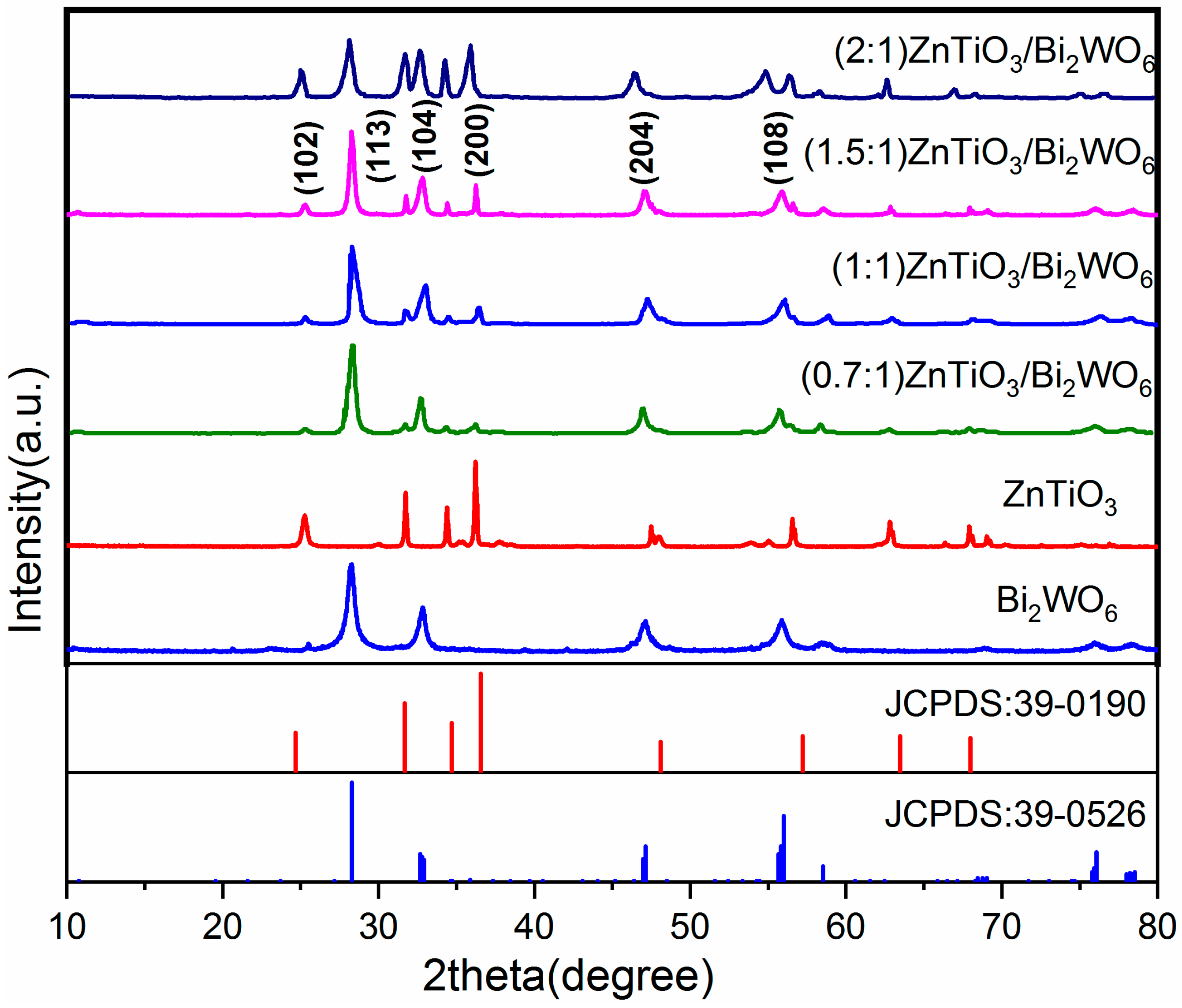
Figure 1. XRD patterns of pure ZnTiO3, pure Bi2WO6, and the ZnTiO3/Bi2WO6 heterojunction.
Molecules 28 03495 g001
Figure 2. (a,b) SEM images of the ZnTiO3 sample; (c,d) SEM images of the ZnTiO3/Bi2WO6 heterojunction sample inset in (d): EDX of the ZnTiO3/Bi2WO6 heterojunction sample; and the elemental O (e), W (f), Bi (g), Zn (h), and Ti (i) mapping of the ZnTiO3/Bi2WO6 heterojunction sample.
Molecules 28 03495 g002
Figure 3. (a) TEM image, (b) HRTEM image, and (c) SAED pattern of the ZnTiO3/Bi2WO6 heterojunction sample.
Molecules 28 03495 g003
Figure 4. XPS spectra of pure Bi2WO6 and ZnTiO3/Bi2WO6 heterojunction: (a) survey spectrum; (b) Bi 4f element spectrum; (c) W 4f element spectrum; (d) O 1s element spectrum; (e) Ti 2p element spectrum; (f) Zn 2p element spectrum.
Molecules 28 03495 g004
Figure 5. (a) Impedance spectrum of the prepared catalyst; (b) transient photocurrent curve of the prepared catalyst.
Molecules 28 03495 g005
Figure 6. (a) Phenol degradation effect and (b) kinetic curve of phenol degradation of ZnTiO3/Bi2WO6 with different molar ratios: (c) p-nitrophenol, (e) p-chlorophenol, and (g) p-methylphenol degradation effect by photocatalysts; and full-spectrum UV analysis of ZnTiO3/Bi2WO6 molar ratio of 1.5:1 for (d) p-nitrophenol, (f) p-chlorophenol, and (h) p-methylphenol.
Molecules 28 03495 g006
Figure 7. Cyclic stability test curve of ZnTiO3/Bi2WO6.
Molecules 28 03495 g007
Figure 8. (a) Intermediates of phenol degradation and (b) mass-to-charge ratio of products after 30, 60, and 90 min of degradation as identified by GC-MS.
Molecules 28 03495 g008
Figure 9. Effect of quencher on phenol degradation rate. (a) Degradation curve diagram, (b) histogram of degradation rate, (c) DMPO-.O2, and (d) DMPO-.OH spin-trapping ESR spectra for Bi2WO6 and Bi2WO6/ZnTiO3.
Molecules 28 03495 g009aMolecules 28 03495 g009b
Figure 10. (a) UV–vis spectroscopy, (b) band gap, (c) valence band position, (d) PL spectroscopy, and (e) work function of the Bi2WO6, ZnTiO3, and Bi2WO6/ZnTiO3 catalysts; and (f) the flat band potentials according to a Mott–Schottky electrochemistry spectroscopy test.
Molecules 28 03495 g010
Figure 11. (a) P-n heterojunction and (b) S-scheme heterojunction mechanism of ZnTiO3/Bi2WO6.
Molecules 28 03495 g011aMolecules 28 03495 g011b
Table 1. The content of various elements in the Bi2WO6/ZnTiO3 sample according to EDX.
ElementWeight %Atomic %
O K46.2590.12
Ti K2.161.41
Zn K1.300.62
W M17.202.92
Bi M33.094.93
Totals100.00100.00
Table 2. Kinetic parameters of the prepared catalyst.
PhotoelectrocatalystsDegradation RateSlopeR2Kinetic Equation
Bi2WO625%0.09130.986Y = 0.0913X + 0.02486
ZnTiO355%0.2640.976Y = 0.264X − 0.07816
ZnTiO3/Bi2WO6(1:1)77%0.4240.989Y = 0.424X
ZnTiO3/Bi2WO6(1.5:1)93%0.95170.992Y = 0.9517X − 0.195
ZnTiO3/Bi2WO6(0.7:1)71%0.34720.971Y = 0.3472X − 0.086
ZnTiO3/Bi2WO6(2:1)81%0.57330.992Y = 0.5733X − 0.126
Disclaimer/Publisher’s Note: The statements, opinions and data contained in all publications are solely those of the individual author(s) and contributor(s) and not of MDPI and/or the editor(s). MDPI and/or the editor(s) disclaim responsibility for any injury to people or property resulting from any ideas, methods, instructions or products referred to in the content.