Article

Nb2O5 Coating to Improve the Cyclic Stability and Voltage Decay of Li-Rich Cathode Material for Lithium-Ion Battery

1
School of Material and Energy, Guangdong University of Technology, Guangzhou 510006, China
2
School of Automobile and Transportation Engineering, Guangdong Polytechnic Normal University, Guangzhou 510640, China
3
College of Petroleum and Chemical Technology, Liaoning Petrochemical University, Fushun 113001, China
*
Authors to whom correspondence should be addressed.
Molecules 2023, 28(9), 3890; https://doi.org/10.3390/molecules28093890
Submission received: 3 March 2023 / Revised: 23 April 2023 / Accepted: 25 April 2023 / Published: 5 May 2023

Abstract

:
The commercialization of lithium manganese oxide (LMO) is seriously hindered by several drawbacks, such as low initial Coulombic efficiency, the degradation of the voltage and capacity during cycling, and the poor rating performance. Developing a simple and scalable synthesis for engineering with surface coating layers is significant and challenging for the commercial prospects of LMO oxides. Herein, we have proposed an efficient engineering strategy with a Nb2O5 coating layer. We dissolved niobate (V) ammonium oxalate hydrate and stoichiometric rich LMO (RLM) in deionized water and stirred constantly. Then, the target product was calcined at high temperature. The discharge capacity of the Nb2O5 coating RLM is increased from 195 mAh·g−1 (the RLM without Nb2O5) to 215 mAh·g−1 at a coating volume ratio of 0.010. The average voltage decay was 4.38 mV/cycle, which was far lower than the 7.50 mV/cycle for the pure LMO. The electrochemical kinetics results indicated that the performance was superior with the buffer engineering by the Nb2O5 coating of RLM, which provided an excellent lithium-ion conduction channel, and improved diffusion kinetics, capacity fading, and voltage decay. This reveals the strong potential of the Nb2O5 coating in the field of cathode materials for lithium-ion batteries.

1. Introduction

Lithium-ion batteries have been widely utilized in various kinds of electronic devices due to their high energy density and long cycling life. Compared with the anode, the cathode material has a lower specific capacity, resulting in a low energy density for advanced devices [1]. Among the recently researched cathodes, the layered Li-rich oxide materials, such as xLi2MnO3·(1 − x)LiMO2 (M = Mn, Ni, Co) (LLMO), have become potential materials to meet the increasing demand for energy density because of their large discharge-specific capacities from 280 to 310 mAhg−1 and high working potential of 3.7 V (vs. Li/Li+). However, there are still some drawbacks to be addressed, such as the cyclic instability, poor rate, fast capacity/voltage decay, and low initial Coulombic efficiency, which limit their large-scale commercial application [2,3,4].
The mechanism of the capacity fade and voltage decay for the LLMO has attracted attention in recent decades [2,3]. An anion redox reaction occurs during the charge and discharge of the LLMO, along with the transformation of the reactant and the intermediate reaction, such as O2−→O2n− and O2−→O2, and the latter reaction is irreversible [5,6,7,8]. The irreversible reaction worsens the electrochemical performance of the LLMO in terms of the electrolyte decomposition and structural reorganization. The continuous electrolyte decomposition on the electrode−electrolyte interface results in the formation of a solid electrolyte interface (SEI) film with high resistance [9,10,11]. The transition metal ions migrate into the Li layer and then induce the phase transformation from the layered to the LiMn2O4 spinel-like structure due to the irreversible release of O2 on the surface. Thus, the LLMO suffers poor cycling stability.
Surface modification has been regarded as an effective strategy to improve the interface stability and thus the electrochemical performance of the LLMO. The surface coating layers usually include three categories. One is an inert material coating, such as ZrO2, SnO2, AlF3, and LiF [12,13,14], which can isolate the electrode and electrolyte and then prevent the electrolyte decomposing and the electrode dissolving. However, a large resistance will be introduced because the coating materials are insulators. Thus, ionic conductors and electric conductors, such as LiAlO2, LiPO4, and C, are widely used as coating materials to resolve the accompanying increased resistance [15,16,17,18]. Among them, the coating of electronic conductors, such as graphene, can increase the conductivity of the material and improve the efficiency of electron transmission. A spinel, for example Li4Mn5O12, is one of the most popular ionic-conductor coating materials, which can not only build an effective electrode−electrolyte interface (EEI) but also provide good Li+ transmission channels and thus good dynamics [19,20]. Additionally, the spinel is still an excellent buffer that can suppress the Mn-based Li-rich material transformation from a layered to a spinel structure, which was also regarded as the main reason for the fast voltage decay of the LLMO. However, the Mn dissolution, homogeneity, appropriate thickness, and the complex preparation technique are still challenges for spinel coating [21,22,23]. Recently, the concept of double-compound coating has been adopted to improve the cyclic life of LLMOs. For example, an improvement in cycling life can be obtained by using a Li4Mn5O12 and MgF2 double-compound as a coating layer, in which Li4Mn5O12 was used as the Li+ transmission channels and MgF2 was used as the separator between the electrode and electrolyte [24]. Nevertheless, the resistance still increases owing to the insulation of MgF2.
Nb2O5 has been widely utilized in the field of biomaterials and lithium-ion batteries owing to its strong corrosive resistance, thermal stability, and high Li+ conductivity [25,26,27]. The effects of the Nb2O5 coating on the cycling life and voltage decay of LLMO have been reported. Wook et al. studied the Nb2O5 coating layer on the LLMO, and Pan et al. further studied the mechanism of the improved cycling life and voltage stability [28,29]. They proposed that the Li+ conductor and the inhabitation of the LLMO in a spinel were the main reasons for the improvement. Nevertheless, the process of Nb2O5 on the LLMO is still not clear. Herein, Nb2O5 was coated on the Li-rich material (RLM-1) to investigate the mechanism of the spinel formation and protection. Then, a new method was proposed to explain the real roles of Nb2O5 during the improved and stable charge and discharge process, which is different from Pan’s one [29]. This discovery may greatly benefit the developing of a more stable Li-rich cathode material.

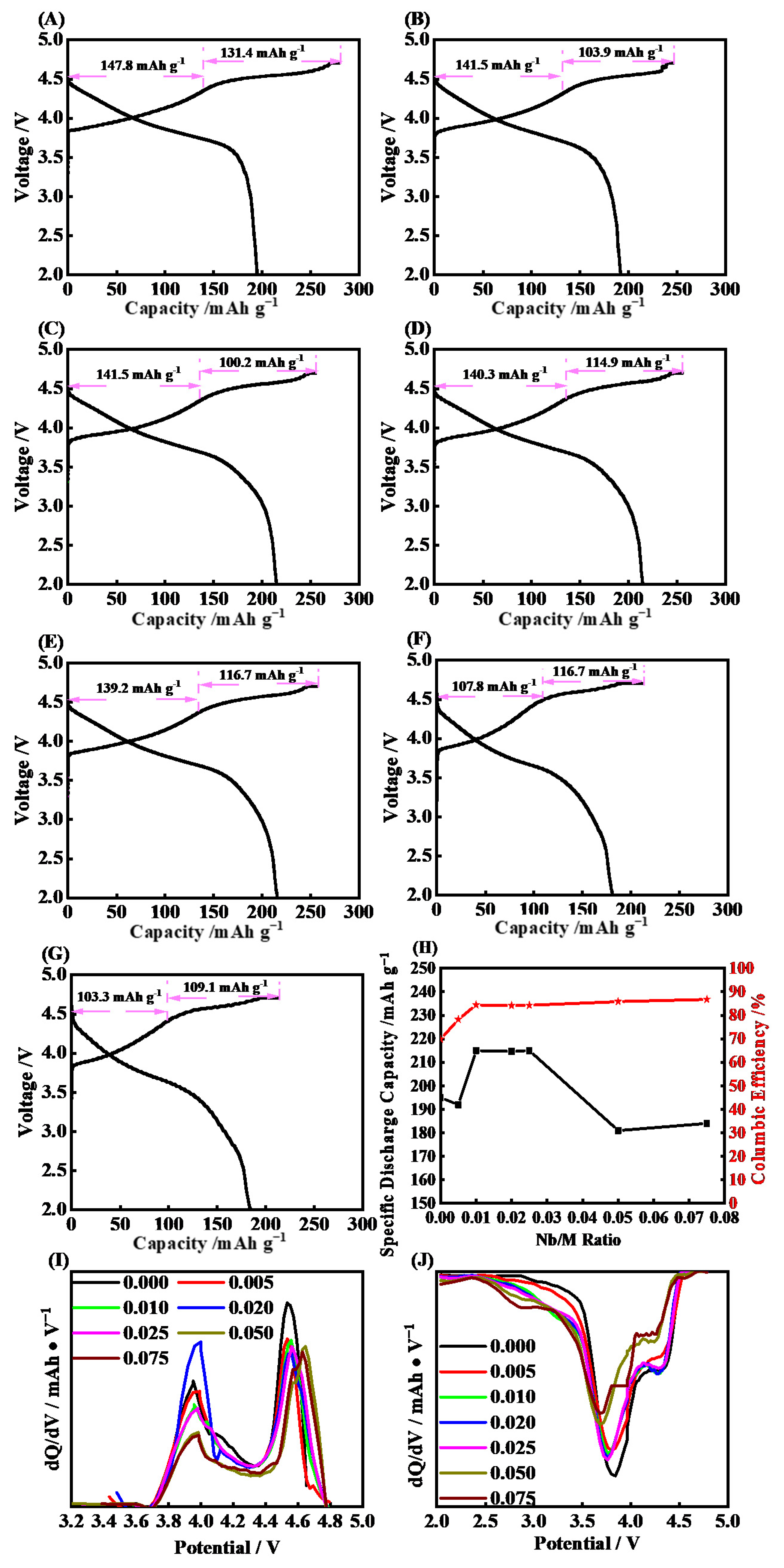
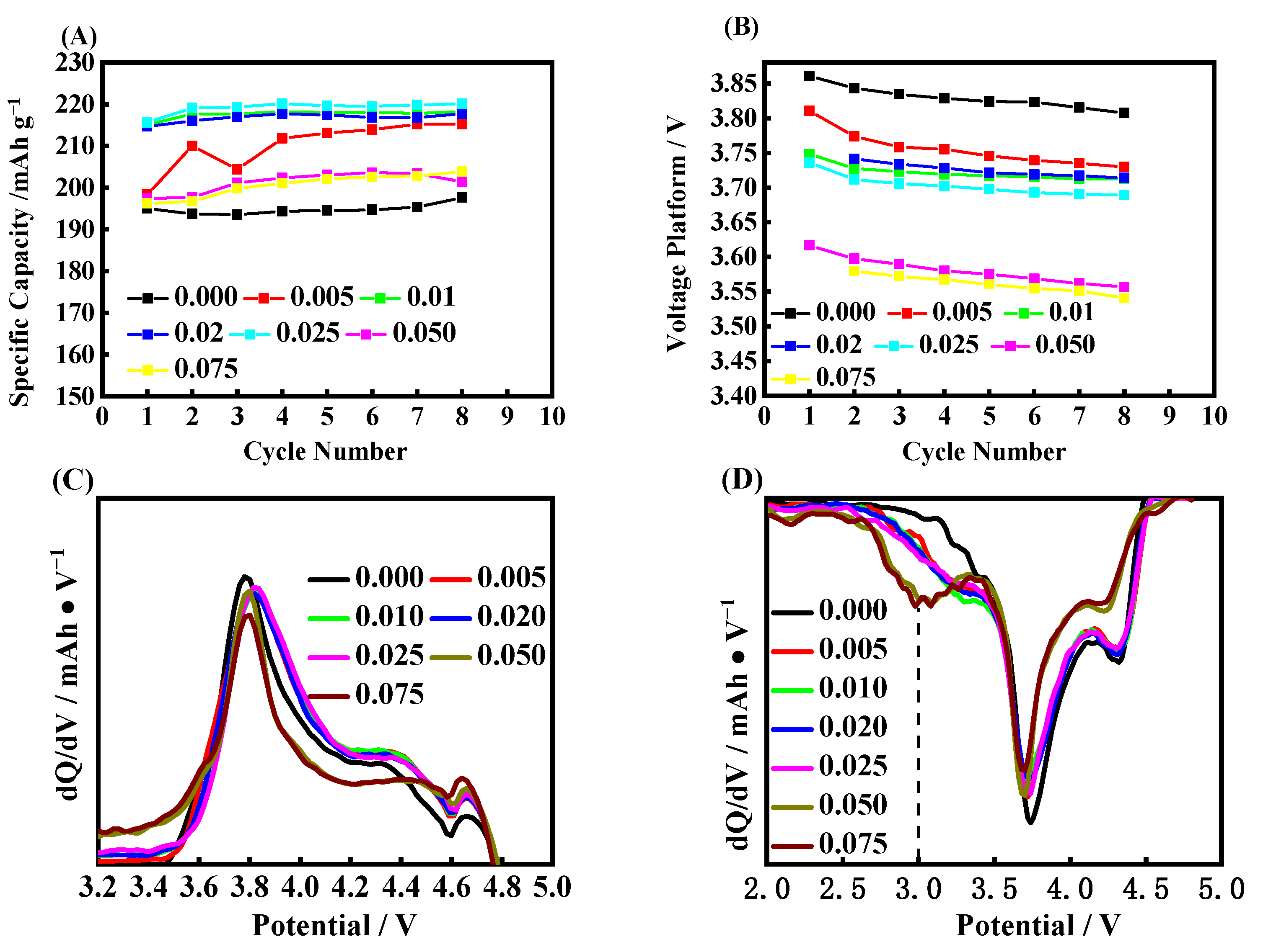
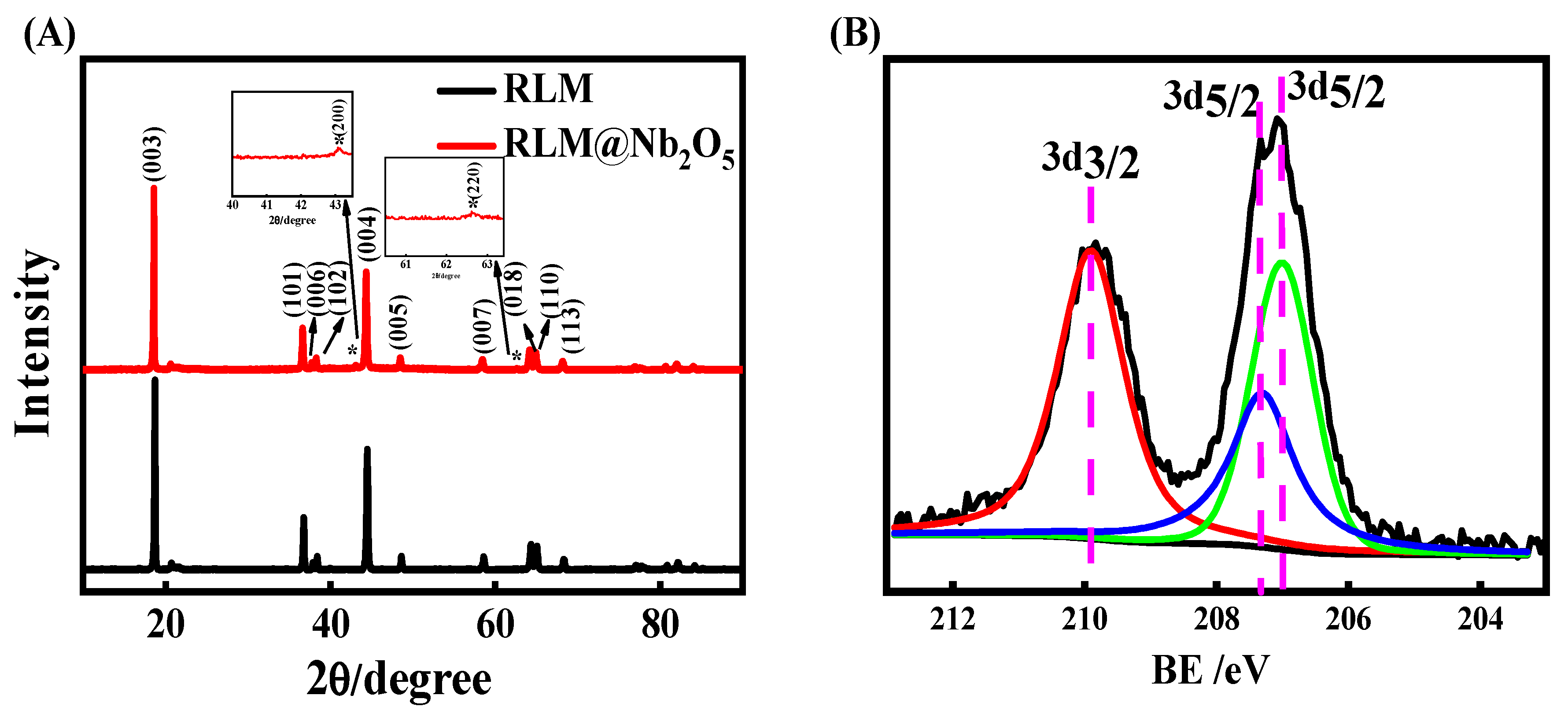
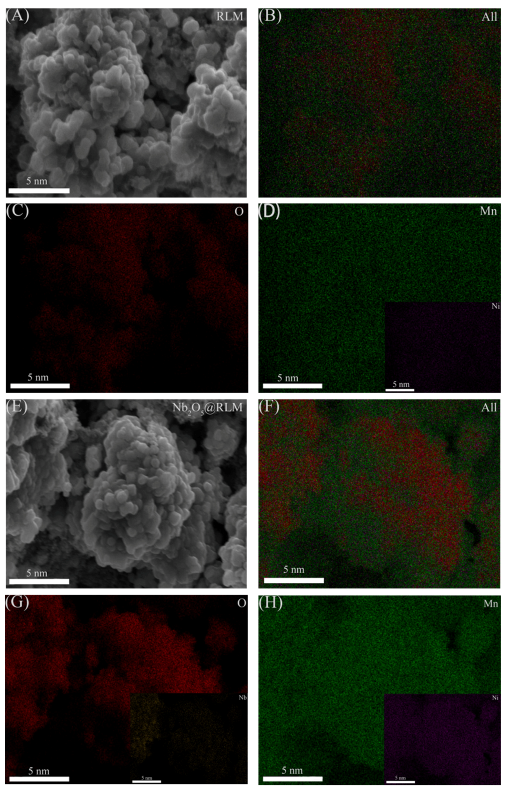
2. Results and Discussion

In Figure 1, it shows the initial charge−discharge curves that were the initial discharge capacities and Coulombic efficiency and dQ/dV curves for RLM-1 coated with different amounts of Nb2O5. All the charge curves consist of the slash before 4.5 V and the platform ca. 4.5 V, corresponding to the oxidation of the transition metal ion, M3+→M4+, and the activation of the Li2MnO3 component, respectively. The latter reaction along with the transfer of Mn and the oxidation of crystal oxygen, O2−→O2n− (n = 1, 2, 3…) is an irreversible process [5,7,8], which leads to the low initial Coulombic efficiency for the Li-rich material. It is noted that the low Coulombic efficiency will also be exacerbated by the irreversible decomposition of the electrolyte, which is caused by the oxygen anion attack on the electrolyte, which showed 69.8% for the blank RLM-1. It is worth noting that a discharge platform is presented in 3.6 V, which is found in the discharge curve of RLM-1, convincingly suggesting the spinel component is involved in the electrochemical reaction process of the first cycle.
Comparatively, similar charge−discharge curves appeared for the Nb2O5-coated RLM-1 (RLM@Nb2O5), which indicated that Nb2O5 did not change the bulk structure of the RLM-1. When the Nb2O5 coating layer was introduced, the discharge capacity gradually increased. Figure 1A−G shows that the discharge capacity increased from 195 mAh·g−1 for the RLM without Nb2O5 to 215 mAh·g−1, which reaches the maximum when n(Nb): n(M) = 0.010. However, when the ratio amount of the Nb2O5 coating layer increased to 0.050, the discharge capacity drops to 184 mAh·g−1, and this dropping trend continues as it increases. To investigate the functional mechanism of Nb2O5 on the enhanced discharge capacity, the dQ/dV curves of each sample were made, as shown in Figure 1I,J. It is observed that the coating layer shows no obvious effect on the position of the voltage peak and current. The peaks are located between 2.7 and 3.0 V and correspond to the reduction in Mn4+ in the spinel phase in the lamellar structure. Therefore, the discharge current appears in the range of 2.75–3.0 V, which is regarded as belonging to the spinel structure formed by the transfer of Mn, and becomes larger as the Nb2O5 amount increases [29]. Additionally, the current peak around 3.7 V shows a blue shift when the Nb2O5 increases, which may due to the introduced resistance by the too-thick Nb2O5 layer. Specifically, the initial Coulombic efficiency shows an obvious increasing trend that accompanies the increase in Nb2O5, and when the Nb: M was 0.010, it reached to 84.4%, which is much higher than others. Thus, it can be seen that the Nb2O5 can reduce the irreversible charge capacity through enhancing the activation of the Li2MnO3 component.
Figure 2A shows the cyclic performance for each kind of coating amount of Nb2O5. We observed that the blank RLM-1 keeps good capacity retention at the beginning of eight cycles. The initial capacity was raised when the Nb2O5 coating layer was introduced when coating ratio was lower than 0.025, and the capacity increased as the ratio began to increase, with the trend remaining steady for the following cycles. It is suggested that the Li2MnO3 component can be fully activated by Nb2O5 coating along with an infiltrating process by the electrolyte. However, the initial capacity begins to fall when the coating ratio exceeds 0.05, which was expected, as the high resistance was also introduced when large amounts of Nb2O5 were used to further investigate the cycling-voltage curves, as shown in Figure 2B. It can be found that the initial voltage and the amount of Nb2O5 show an anti-correlation relationship. The initial voltage becomes lower, but the voltage decay becomes slower. The average voltage decay for the coating ratio of 0.010 is 4.38 mV/cycle, which is far lower than the 7.50 mV/cycle for the blank one. Thus, it is suggested that the Nb2O5 coating is beneficial for easing the voltage decay of Li-rich material; therefore, the optimal coating ratio is 0.010.
The dQ/dV curves of the eighth circle for each group are shown in Figure 2C,D. All of them have a current charge after 4.4 V, even if it is at the 8th circle, indicating that they have reversibility to a certain extent above 4.4 V, which has also been reported in the literature. The amount of coating has no obvious influence on the charging voltage peak and current. It is worth noting that there is a spinel discharge current around 2.75–3.0 V, which does not exist in the first cycle for the blank RLM-1, suggesting some phase transformations occur [29]. Comparatively, the spinel discharge current becomes obvious when the Nb2O5 is used, even if the coating ratio is only 0.005, which means that this coating can effectively accelerate the formation of the spinel phase, the amount of which is highly positively correlated with the ratios of the introduced Nb2O5. This may be due to the changed dynamic processes, which were related to the topotaxial factors, such as the migration channels of Li+, Mn, and O for the phase transformation of Li2MnO3 to spinel [30]. There are no obvious differences among all the samples for the coating ratio below 0.050. Moreover, the spinel current also shows little change compared with the first-cycle discharge, as shown in Figure 1J, when the coating ratio was at the range of 0.010–0.025, suggesting that the spinel nearly formed less at the following cycles. This explains the lower initial voltage and the slower voltage decay for the Nb2O5 coating material, and also agrees with the known mechanism of voltage decay for Li-rich material, namely, formed spinel. Notably, a larger response current below 3.6 V for the 0.050 and 0.075 coating ratios is observed, and this can be ascribed to the excessive spinel phase formed by the increasing amount of Nb2O5. Moreover, the huge decrease in the layered structural component was implicated in the excessive spinel phase forming, resulting in the smaller current in the range of 3.8–4.6 V. The obviously positive shift of the charging peaks indicates the larger polarization caused by the excessive Nb2O5 when the coating ratio is above 0.050.
Figure 3 displays the cycling performance for each sample with Nb/M 0.010 calcined with 550 °C, 600 °C, 650 °C, 700 °C, 750 °C, 800 °C, 850 °C, and 900 °C. The sample delivery is 195 mAh·g−1 when the calcined temperature is 550 °C, indicating that the low temperature has no influence on the discharge capacity. It is raised as the temperature increased, and it reaches the highest level of 215 mAh·g−1 when the temperature is at 850 °C. The initial Coulombic efficiency shows a similar trend, and it reaches 78.7% at the calcined temperature of 800 °C. Although the discharge platform shows a downward trend with the increase in calcination temperature, the decay rate gradually decreases and the average voltage decay is 11.49 mV/cycle for 550 °C, while it is only 7.76 mV/cycle for 850 °C for the first 8 cycles. Combining the initial charge−discharge curves and the dQ/dV differential curves, as shown in Figure 3C−E, on the one hand, it can be found that the temperature increase accompanies the polarization of the electrode, as the first oxidation potential shows a slight positive shift. On the other hand, although each sample has discharge peaks at 4.3 V, 3.75 V, and 3.0 V, respectively, the current of the spinel phase corresponds to the peak at around 3.0 V for a temperature of 550 °C, which is slightly lower than other samples. Additionally, the current shows a slight increase as the temperature trend continues upward. This can be attributed to the better crystallization of Nb2O5 under the higher calcined temperature, which provides an excellent transmitting channel for oxygen anions, the Mn, and Li+ to form spinel, as well as creating a small discharge polarization. However, the increase in temperature also increases the particle size of Nb2O5 crystals, which can be found in the Supplementary Information Figures S1–S3, which leads to the long Li+ transmission distance and large polarization. Thus, it shows the decreased discharge capacity and the low Coulombic efficiency. Our analysis shows that the 850 °C calcination temperature for the samples is the optimum, which is suggested to be utilized in future research.
Figure 4A shows the XRD patterns of the RLM-1 and RLM@Nb2O5 materials with a coating ratio of 0.010 calcined at 850 °C. In both of them, there is a splitting peak at 20–23°, corresponding to the Li/Mn cations mixed in the monoclinic C2/m Li2MnO3 region, which are considered to be characteristic of the diffraction peaks of Li-rich materials [3,31]. The Nb2O5 coating has no influence on the diffraction peaks of RLM-1, indicating that the Nb2O5 coating layer does not change the main lattice of the RLM-1. The peaks at 42.9° and 62.3° correspond to the (200) and (220) crystal planes of NbO, re-spectively. The peak intensity ratios of RLM@Nb2O5(101)/(003) were 0.230 and (004)/(003) were 0.539, while the peak intensities of (101)/(003) and (004)/(003) of RLM-1 were 0.2612 and 0.603, respectively. The half-peak width of the main peak of the sample with Nb2O5 compared with RLM-1 was 1.031. The half-widths of the peaks are hardly changed, so Nb2O5 does not change the main lattice of RLM-1. Additionally, the content of Nb2O5 is small, and only extremely weak diffraction peaks of Nb2O5 are detected in the XRD diffraction patterns around 43° and 62°. In addition, as shown in Figure 4B, it can be observed that the 3d3/2, 3d5/2, and 3d5/2 peaks in photoelectron spectroscopy (XPS) are located at 209.9, 207.3 and 207.1 ev, respectively, which belong to Nb2O5 [32,33]. This indicates that Nb2O5 had been effectively coated on the surface of RLM-1.
Figure 5 shows the element mapping of RLM-1 and RLM@Nb2O5 materials, and it could be observed that the Ni, Mn, and O elements are distributed very uniformly before and after the coating, indicating that the coating has no influence on the homogeneous nature of each element inside the material. Moreover, the signal of the Nb element can be observed in the RLM@Nb2O5 material. However, its signal intensity is weak, which may be attributed to the low concentration of Nb, as shown in Figure 5G, indicating that the Nb2O5-coated layer is even.
Figure 6A shows the improvement in the Nb2O5 coating for RLM-1. The blank RLM-1 shows a serious degradation at 170 cycles, and the capacity is 83.1 mAhg−1, only about 42.1% of the initial capacity at 300 cycles. Comparing with RLM-1, the RLM@Nb2O5 shows good cycling performance with a capacity retention of 81.5% at 300 cycles. This suggests that the proper coating proportion with Nb2O5 can effectively inhibit the capacity decay of a lithium-rich cathode. It is found that the voltage platform trend presents a similar behavior, which reveals a fast decay at 170 cycles for blank RLM-1 while retaining a good stability for RLM@Nb2O5, as shown in Figure 6B. The voltage platform retention is calculated by the Formula (1):
η = V cycle V initial × 100 %
where η represents the voltage platform retention; Vinitial represents the discharge voltage plateau of the first cycle; Vcycle represents the discharge voltage plateau for the corresponding number of cycles.
The discharge voltage plateau of RLM-1 dropped from the initial 3.8604 V to 3.3664 V, with a voltage retention of 87.2% and average decay of 1.65 mV/cycle for 300 cycles. After coating with Nb2O5, the voltage decay was eased from 3.7709 V to 3.5789 V, with a voltage retention of 94.9% and average decay of 0.64 mV/cycle. This indicates that Nb2O5 coating can also effectively suppress the voltage decay of Li-rich materials. It is worth noting that the RLM@Nb2O5 shows a large capacity fade at 210 cycles, while there is no corresponding accelerated voltage decay, indicating that there is no certain relationship between the capacity fade and voltage decay, which is utilized to explain the real reason for the long-time voltage decay of lithium-rich materials.
From the dQ/dV analysis, as seen Figure 6C, it can be found that both RLM-1 and RLM@Nb2O5 show similar electrochemical behaviors, namely, charging peaks between 3.5 and 3.75 V and broad discharge peaks around 4.1 V and 3.0–3.6 V before 150 cycles. There are small charging peaks of about 4.5 V for RLM-1 at the 150th cycle, which indicates that the activated Li2MnO3 structures still lack wrapping. The RLM-1 shows a large polarization and irreversibility with the charge current peak between 3.5 and 3.75 V, and the discharge current above 3.7 V completely disappeared after 300 cycles, while it kept the same electrochemical performance with 150 cycles for RLM@Nb2O5. Figure 6D shows the impedance diagram of two samples after 300 cycles. The entire impedance diagram is composed of two semicircles in the middle- and high-frequency regions, indicating the solid electrolyte−electrode interface film (abbreviated as EEI) has been formed on the surface of the electrode. It can be found that the solution impedance Rs of the two samples is nearly equivalent. The REEI of the RLM-1 in the high-frequency region is greater than that of RLM@Nb2O5. This may be due to the thicker poor-conductivity film formed by the deposition of electrolyte decomposition on the surface of the RLM-1 material. Moreover, the ion conductivity of Nb2O5 coating also reduces the resistance of the film. In the mid-frequency region, the impedance semicircle radius of RLM-1 is smaller than that of RLM@Nb2O5, indicating a lower charge transfer resistance Rct of RLM-1 than that of RLM@Nb2O5. This may be due to the reduced size of the Li+ transmission distance by the powdering process of material particles during cycling, while Nb2O5-coated RLM-1 maintains particle integration and also shows higher Rct. The parameters are shown in Table 1. As mentioned above, the better cyclic stability and lower voltage decay originates from the Nb2O5 coating layer’s modified surface.
The TEM images of RLM-1 and Nb2O5 RLM before and after 300 cycles are presented in Figure 7. It can be found from Figure 7A that the original RLM-1 was covered by a homogeneous coating, a dense and amorphous layer with about 4 nm thickness. The thickness of the original covered layer has no change after secondary Nb2O5 coating; however, some integral crystalline Nb2O5 was observed and passed through the covered layer, as shown in Figure 7B. This can provide good channels for Li+- and O2--exchange between the electrode material and electrolyte because of the good lattice as well as the ion conductivity. After 300 cycles, the RLM-1 particles were completely exposed in the electrolyte and broken up, with the original covered layer completely destroyed, as presented in Figure 8C. This also explains the phenomenon of the fast capacity fade and voltage decay for RLM-1. It indicated that RLM-1 cannot be protected effectively by the original amorphous layer. Comparatively, the original covered layer still exists and has no obvious change after 300 cycles for the RLM@Nb2O5. Remarkably, comparing with the RLM-1, a new spinel layer was formed between the original cover and the bulk material for the RLM@Nb2O5. This can be explained as the Nb2O5 crystal providing good channels for Li+ and O2− exchange, resulting in a lower oxygen anion, which is beneficial for forming the spinel structure during the Li2MnO3 activation process. Moreover, the high-concentration spinel-phase structure not only provides the Li+ channels [19,20] but also inhibits the further forming of spinel, which causes the lower initial discharge voltage platform and the smaller voltage decay for the RLM@Nb2O5.
The SEM images show similar results as above, shown in Figure 8. It can be clearly seen that the particle sizes of RLM-1 and RLM@Nb2O5 were about 10 μm, stacking with lots of smooth and smaller particles, indicating that Nb2O5 coating has no influence on the topography of RLM-1. However, the boundary between the particles becomes fuzzy and covered by lots of electrolyte decomposition after 300 cycles for RLM-1. Comparatively, the morphology of RLM@Nb2O5 has no obvious change. Especially, it does not exhibit the electrolyte decomposition, which indicates that Nb2O5 secondary coating can suppress the decomposition of electrolytes.
XPS spectra were conducted to analyze the surface compositions of Li-rich electrodes after 300 cycles. As shown in Figure 9, in the C 1s spectrum, the peak at 284.3 eV is ascribed to the conductive carbon [32]. The peaks at 286.5 eV, 288.6 eV, and 290.8 eV are assigned to the C-O, C=O, and C-F groups of ROCO2Li, ROLi, and PVDF species, respectively, which result from the electrolyte decomposition [32,34]. Considering the larger C-O intensity of RLM-1 than that of RLM@Nb2O5, it should be concluded that a lot of electrolytes were decomposed and deposited on the surface of the RLM-1 electrode.
In the O 1s spectrum, the peaks at 531.3–531.5 eV (C=O, Li-O), 533–534 eV (C-O), and 529.8 eV (M-O) are characteristic of polycarbonates, lithium alkyl carbonates, and metal oxide, respectively [35]. The weaker intensity of these peaks for the RLM@Nb2O5 electrode compared with RLM-1 suggests that more electrode was exposed due to the surface coating layer being damaged. It should be noticed that the peak intensities between 531.3 and 531.5 eV are the multiple peaks for the C=O of polycarbonates and Li-O of Li2O. According to the C 1s spectrum, the C=O peak of RLM@Nb2O5 should be smaller than that of RLM-1 because less electrolyte being decomposed. Interestingly, the peak intensity in the range of 531.3–531.5 eV for RLM@Nb2O5 is larger than that for RLM-1, indicating that there is more Li2O on the surface of RLM@Nb2O5 [35,36,37,38,39]. The Li2O was formed by the reaction of O2− and Li+ during Li2MnO3 activation, which can be scripted as 5Li2MnO3 → Li4Mn5O12 + 3Li2O, which produced Li2O and the spinel structure simultaneously. This result corresponds with the description of the spinel behavior mentioned above, since the local structure changes to the spinel structure in the Li2MnO3 component are caused by Li+ extraction, which was confirmed by Yu’s group [40,41,42]. The larger spinel structure and Li2O can account for the accelerated O and Li+ extraction from the Li2MnO3 component, as well as the faster dynamic processes induced by the lower topotaxial factor of O and Li+ from the better O and Li+ channels that are provided by Nb2O5 coating layer [19,20,30]. The view of the above-mentioned accelerated spinel-formation process is different from the one that observed by Pan et al. [29]. In the F 1s spectra, the peaks of 687.5 eV, 686.2 eV, and 685.0 eV correspond to PVDF, LixPOyFz, and LiF, respectively [39]. They produced a small amount of LiF through the reaction with HF in contact with the electrode, meaning they have a critical role in maintaining the fasting Li-ion diffusion kinetics and the wonderful electrochemical performance of the electrode. The weaker peak intensity of LixPOyFz for the RLM@Nb2O5 electrode suggests less electrolyte decomposition [34]. The Nb signal of the RLM@Nb2O5 electrode after 300 cycles further confirms that Nb2O5 plays a role across the whole cycling life.

3. Experiment Section

3.1. Preparation of Nb2O5 Coated Samples

An appropriate amount of ammonium niobate (V) oxalate hydrate was dissolved in deionized water and then constantly stirred for 30 min. After the stoichiometric RLM-1 was added into the solution above, the mixture was constantly stirred under room temperature for 3 h and then heated at 75 °C. The molar ratios of Nb to M (M = Ni, Co, Mn) are 0.005, 0.010, 0.020, 0.025, 0.050, and 0.075, respectively. The obtained powder was dried at 100 °C for 12 h in vacuum, preheated at 500 °C for 6 h, and then calcinated at 900 °C for 12 h with 2 °C/min. RLM-1 was purchased from Jiangxi Jiangte Lithium-Ion Battery Material Co. (Chaoxia Road, Pharmaceutical Industrial Park, Yuanzhou District, Yichun City, Jiangxi Province, China), Ltd. In addition, the calcining temperatures were also studied from 550 to 900 °C.

3.2. Physical Characterizations

The crystalline structures of the resulting samples were characterized using an X-ray diffractometer (XRD, D8 Advance, Bruker, Germany) in the 2θ range of 10–80° at an interval of 0.2 °/min. The particle sizes were measured by a laser particle-size analyzer (BT-9300HT, SuZhou Hinos Industrial Co., China). The morphologies and nano structures were observed using scanning electron microscopy (SEM, ZEISS Ultra 55, Zeiss, Germany) and transmission electron microscopy (TEM, JEM-2100HR, JEOL, Japan), respectively. X-ray photoelectron spectroscopies (XPS) were conducted on a Thermo Scientific TM K-Alpha TM+ spectrometer equipped with a monochromatic Al Kα X-ray source (1486.6 eV) operating at 100 W. Samples were analyzed under vacuum (p < 10−8 mbar) with a pass energy of 150 eV (survey scans) or 25 eV (high-resolution scans). All the peaks were calibrated with C1s peak binding energy at 284.3 eV. The experimental peaks were fitted with XPSPEAK41 software.

3.3. Electrochemical Measurements

For electrochemical measurements, the electrodes were prepared by coating the slurry including 93 wt.% active material, 4 wt.% conductive carbon (Super P), and 3 wt.% binder (polyvinylidene fluoride) onto Al foils. CR2032 coin cells were assembled in a glove box filled with highly pure Ar using the prepared electrode as the working electrode and Li metal as the counter electrode. In total, 1.0 mol dm−3 LiPF6 in ethylene carbonate (EC)/ethyl methyl carbonate (EMC)/diethyl carbonate (DEC) (1:1:1 wt.%) (Dongguan Kaixin Battery Material Co., Ltd., Dongguan, China) was used as the electrolyte, and we used a microporous membrane of 16 μm (purchased from Shenzhen, China, Senior Technology Material Co, Ltd.) as the separator. Charge−discharge tests were carried out on a land testing system in the range of 2.0–4.8 V. The electrochemical impedance spectroscopy measurements were carried out at 3.15 V at the specific cycle on the Autolab PGSTAT302 from 100 KHz to 0.01 Hz with 5 mV amplitude.

4. Conclusions

The Nb2O5 secondary coating can effectively improve the first Coulombic efficiency, capacity fade, and voltage decay of the commercial lithium-rich manganese-based cathode. A simple amorphous coating layer cannot protect the Li-rich material effectively for a long cycling life. The Nb2O5-coated Li-rich materials with low resistance, high capacity, and voltage stability can be obtained when the coating ratio is 0.010 and the calcining temperature is 850 °C. Nb2O5 with a high crystalline structure can provide excellent oxygen anion and Li+ transport channels during Li2MnO3 activation and then accelerate the spinel formed at the coating region to build a stable and highly dynamic coating layer [19,20]. The spinel formed at an early stage can suppress the formation in the following cycles and ease the voltage decay during cycling. Moreover, the inert Nb2O5 coating layer can effectively protect the electrode material from corrosion and inhibit the oxidation and decomposition of the electrolyte.

Supplementary Materials

The following supporting information can be downloaded at: https://www.mdpi.com/article/10.3390/molecules28093890/s1, Figure S1: The microscope images of samples obtained at 550 °C, 600 °C, 650 °C, 700 °C, 750 °C, 800 °C, 850 °C, and 900 °C, respectively; Figure S2: The particle size of samples obtained at 550 °C, 600 °C, 650 °C, 700 °C, 750 °C, 800 °C, 850 °C, and 900 °C, respectively; Figure S3: dQ/dV curves of the initial cycle (A,B), and dQ/dV curves of the 8th cycle (C,D) for different coating ratios of RLM@Nb2O5, dQ/dV curves of the 1th cycle (E,F) and 8th cycle (G,H) of the samples obtained at550 °C, 600 °C, 650 °C, 700 °C, 750 °C, 800 °C, 850 °C, and 900 °C.

Author Contributions

Conceived and designed the experiments, X.L., Y.L. (Yuanwei Lin) and L.W.; Performed the experiments, Y.L. (Yanlin Liu), R.Y., X.L. and L.W.; Analyzed the data, Y.L. (Yanlin Liu), R.Y. and W.Y.; Contributed reagents/materials/analysis tools, X.L., G.Z. and L.W.; Wrote the paper, Y.L. (Yanlin Liu), R.Y., X.L. and L.W. All authors have read and agreed to the published version of the manuscript.

Funding

The authors appreciate the support of the National Natural Science Foundation of China (Grant No. 22005063).

Institutional Review Board Statement

Not applicable.

Informed Consent Statement

Not applicable.

Data Availability Statement

The corresponding dates have been provided in paper. And there is no new data that were created.

Conflicts of Interest

The authors declare no conflict of interest.

Sample Availability

Samples of the compounds RLM@Nb2O5 are available from the authors.

References

  1. Hu, X.S.; Zhang, K.; Liu, K.L.; Lin, X.K.; Dey, S.; Onori, S. Advanced Fault Diagnosis for Lithium-Ion Battery Systems: A Review of Fault Mechanisms, Fault Features, and Diagnosis Procedures. IEEE Ind. Electron. Mag. 2020, 14, 65–91. [Google Scholar] [CrossRef]
  2. Hu, S.J.; Pillai, A.S.; Liang, G.M.; Pang, W.K.; Wang, H.Q.; Li, Q.Y.; Guo, Z.P. Li-Rich Layered Oxides and Their Practical Challenges: Recent Progress and Perspectives. Electrochem. Energy Rev. 2019, 2, 277–311. [Google Scholar] [CrossRef]
  3. Zhao, S.; Yan, K.; Zhang, J.; Sun, B.; Wang, G. Reaction Mechanisms of Layered Lithium-Rich Cathode Materials for High-Energy Lithium-Ion Batteries. Angew. Chem. Int. Ed. 2020, 60, 2208–2220. [Google Scholar] [CrossRef] [PubMed]
  4. Eum, D.; Kim, B.; Kim, S.J.; Park, H.; Kang, K. Voltage decay and redox asymmetry mitigation by reversible cation migration in lithium-rich layered oxide electrodes. Nat. Mater. 2020, 19, 1–9. [Google Scholar] [CrossRef]
  5. Cao, X.; Li, H.; Qiao, Y.; Jia, M.; Zhou, H. Structure design enables stable anionic and cationic redox chemistry in a T2-type Li-excess layered oxide cathode. Sci. Bull. 2021, 67, 381–388. [Google Scholar] [CrossRef]
  6. Li, M.; Liu, T.; Bi, X.; Chen, Z.; Amine, K.; Zhong, C.; Lu, J. Cationic and anionic redox in lithium-ion based batteries. Chem. Soc. Rev. 2020, 49, 1688–1705. [Google Scholar] [CrossRef]
  7. Mccalla, E.; Abakumov, A.M.; Saubanere, M.; Foix, D.; Berg, E.J.; Rousse, G.; Doublet, M.L.; Gonbeau, D.; Novak, P.; Van Tendeloo, G. Visualization of O-O peroxo-like dimers in high-capacity layered oxides for Li-ion batteries. Science 2015, 350, 1516. [Google Scholar] [CrossRef]
  8. House, R.A.; Rees, G.J.; Pérez-Osorio, M.; Marie, J.J.; Boivin, E.; Robertson, A.W.; Nag, A.; Garcia-Fernandez, M.; Zhou, K.J.; Bruce, P.G. First-cycle voltage hysteresis in Li-rich 3d cathodes associated with molecular O2 trapped in the bulk. Nat. Energy 2020, 5, 777–785. [Google Scholar] [CrossRef]
  9. Mt, A.; Rk, A.; Ky, B. High-capacity Li-excess lithium nickel manganese oxide as a Co-free positive electrode material. Mater. Res. Bull. 2020, 137, 111178. [Google Scholar]
  10. Si, M.; Wang, D.; Zhao, R.; Pan, D.; Zhang, C.; Yu, C.; Lu, X.; Zhao, H.; Bai, Y. Local Electric-Field-Driven Fast Li Diffusion Kinetics at the Piezoelectric LiTaO3 Modified Li-Rich Cathode–Electrolyte Interphase. Adv. Sci. 2020, 7, 1902538. [Google Scholar] [CrossRef]
  11. Leanza, D.; Mirolo, M.; Vaz, C.; Novák, P.; Elkazzi, M. Surface Degradation and Chemical Electrolyte Oxidation Induced by the Oxygen Released from Layered Oxide Cathodes in LiIon Batteries. Batter. Supercaps 2019, 2, 482–492. [Google Scholar] [CrossRef]
  12. Yao, L.; Liang, F.; Jin, J.; Chowdari, B.; Wen, Z. Improved electrochemical property of Ni-rich LiNi0.6Co0.2Mn0.2O2 cathode via in-situ ZrO2 coating for high energy density lithium ion batteries. Chem. Eng. J. 2020, 389, 124403. [Google Scholar]
  13. Chen, Z.; Liu, Y.; Lu, Z.; Hu, R.; Cui, J.; Xu, H.; Ouyang, Y.; Zhang, Y.; Zhu, M. Plasma-assisted coating of nanosized SnO2 on LiNi0.5Co0.2Mn0.3O2 cathodes for enhanced cyclic stability of lithium-ion batteries. J. Alloys Compd. 2019, 803, 71–79. [Google Scholar] [CrossRef]
  14. Du, Z.L.; Peng, W.J.; Wang, Z.X.; Guo, H.J.; Hu, Q.Y.; Li, X.H. Improving the electrochemical performance of Li-rich Li1.2Ni0.13Co0.13Mn0.54O2 cathode material by LiF coating. Ionics 2018, 24, 3717–3724. [Google Scholar] [CrossRef]
  15. Liu, Y.J.; Fan, X.J.; Zhang, Z.Q.; Wu, H.H.; Liu, D.M.; Dou, A.C.; Su, M.R.; Zhang, Q.B.; Chu, D.W. Enhanced Electrochemical Performance of Li-Rich Layered Cathode Materials by Combined Cr Doping and LiAlO2 Coating. Acs Sustain. Chem. Eng. 2019, 7, 2225–2235. [Google Scholar]
  16. Fu, C.C.; Wang, J.Y.; Wang, J.F.; Meng, L.L.; Zhang, W.M.; Li, X.T.; Li, L.P. A LiPF6-electrolyte-solvothermal route for the synthesis of LiF/LixPFyOz-coated Li-rich cathode materials with enhanced cycling stability. J. Mater. Chem. A 2019, 7, 23149–23161. [Google Scholar]
  17. Xiao, W.; Nie, Y.; Miao, C.; Wang, J.L.; Tan, Y.; Wen, M.Y. Structural design of high-performance Ni-rich LiNi0.83Co0.11Mn0.06O2 cathode materials enhanced by Mg2+ doping and Li3PO4 coating for lithium ion battery. J. Colloid Interface Sci. 2022, 607, 1071–1082. [Google Scholar] [CrossRef]
  18. Deng, Z.; Wei, Q.; Wan, G.; Zhao, G.; Shi, S.; Mou, P.; Teng, S.; Du, C.; Wang, G. Synergistic effect of nanosheet structure and carbon coating engineering to enhance lithium storage performance of molybdenum niobium oxides. Mater. Today Sustain. 2022, 19, 100176. [Google Scholar] [CrossRef]
  19. Zhang, X.D.; Shi, J.L.; Liang, J.Y.; Yin, Y.X.; Zhang, J.N.; Yu, X.Q.; Guo, Y.G. Suppressing Surface Lattice Oxygen Release of Li-Rich Cathode Materials via Heterostructured Spinel Li4Mn5O12 Coating. Adv. Mater. 2018, 30, 1801751. [Google Scholar]
  20. Zhang, W.; Sun, Y.G.; Deng, H.Q.; Ma, J.M.; Zeng, Y.; Zhu, Z.Q.; Lv, Z.S.; Xia, H.R.; Ge, X.; Cao, S.K.; et al. Dielectric Polarization in Inverse Spinel-Structured Mg2TiO4 Coating to Suppress Oxygen Evolution of Li-Rich Cathode Materials. Adv. Mater. 2020, 32, 2000496. [Google Scholar] [CrossRef]
  21. Xie, H.X.; Cui, J.X.; Yao, Z.; Ding, X.K.; Zhang, Z.H.; Luo, D.; Lin, Z. Revealing the role of spinel phase on Li-rich layered oxides: A review. Chem. Eng. J. 2022, 427, 131978. [Google Scholar] [CrossRef]
  22. Li, J.L.; Jia, T.K.; Tang, C.J.; Yu, D.S.; Sun, J.; Zhang, W.Z.; Wang, Y.J.; Lee, J.H.; Kim, N.H. Stabilizing voltage and prolonged cycling life of Li-rich Mn-based oxides through spinel “lithium ion pump” heteroepitaxial coating strategy. Scr. Mater. 2021, 204, 114133. [Google Scholar] [CrossRef]
  23. Young, M.J.; Letourneau, S.; Warburton, R.E.; Dose, W.M.; Johnson, C.; Greeley, J.; Elam, J.W. High-Rate Spinel LiMn2O4 (LMO) Following Carbonate Removal and Formation of Li-Rich Interface by ALD Treatment. J. Phys. Chem. C 2019, 123, 23783–23790. [Google Scholar] [CrossRef]
  24. Zhu, W.; Tai, Z.G.; Shu, C.Y.; Chong, S.K.; Guo, S.W.; Ji, L.J.; Chen, Y.Z.; Liu, Y.N. The superior electrochemical performance of a Li-rich layered cathode material with Li-rich spinel Li4Mn5O12 and MgF2 double surface modifications. J. Mater. Chem. A 2020, 8, 7991–8001. [Google Scholar] [CrossRef]
  25. Abood, M.; Salim, E.T.; Saimon, J.A. Optical investingations of Nb2O5 at different temperature for optoelectronic devices. J. Ovonic Res. 2019, 15, 109–115. [Google Scholar]
  26. Arico, C.; Ouendi, S.; Taberna, P.L.; Roussel, P.; Simon, P.; Lethien, C. Fast Electrochemical Storage Process in Sputtered Nb2O5 Porous Thin Films. Acs Nano 2019, 13, 5826–5832. [Google Scholar] [CrossRef]
  27. Meng, J.S.; He, Q.; Xu, L.H.; Zhang, X.C.; Liu, F.; Wang, X.P.; Li, Q.; Xu, X.M.; Zhang, G.B.; Niu, C.J.; et al. Identification of Phase Control of Carbon-Confined Nb2O5 Nanoparticles toward High-Performance Lithium Storage. Adv. Energy Mater. 2019, 9, 1802695. [Google Scholar] [CrossRef]
  28. Yuan, H.; Song, W.B.; Wang, M.; Gu, Y.J.; Chen, Y.B. Lithium-ion conductive coating layer on nickel rich layered oxide cathode material with improved electrochemical properties for Li-ion battery. J. Alloys Compd. 2019, 784, 1311–1322. [Google Scholar] [CrossRef]
  29. Pan, W.; Peng, W.; Yan, G.; Guo, H.; Wang, Z.; Li, X.; Gui, W.; Wang, J.; Chen, N. Suppressing the Voltage Decay and Enhancing the Electrochemical Performance of Li1.2Mn0.54Co0.13Ni0.13O2 by Multifunctional Nb2O5 Coating. Energy Technol. 2018, 6, 2139–2145. [Google Scholar] [CrossRef]
  30. Phillips, P.J.; Bareno, J.; Li, Y.; Abraham, D.P.; Klie, R.F. On the Localized Nature of the Structural Transformations of Li2MnO3 Following Electrochemical Cycling. Adv. Energy Mater. 2015, 5, 1501252. [Google Scholar] [CrossRef]
  31. Nayak, P.K.; Erickson, E.M.; Schipper, F.; Penki, T.R.; Munichandraiah, N.; Adelhelm, P.; Sclar, H.; Amalraj, F.; Markovsky, B.; Aurbach, D. Review on Challenges and Recent Advances in the Electrochemical Performance of High Capacity Li- and Mn-Rich Cathode Materials for Li-Ion Batteries. Adv. Energy Mater. 2018, 8, 1702397. [Google Scholar] [CrossRef]
  32. Chen, H.; Liu, B.; Wang, Y.; Guan, H.; Zhou, H.M. Insight into wide temperature electrolyte based on lithiumdifluoro (oxalate)borate for high voltage lithium-ion batteries. J. Alloys Compd. 2021, 876, 159966. [Google Scholar] [CrossRef]
  33. Yang, F.; Li, W.Y.; Rui, Y.C.; Tang, B.H.J. Improved Specific Capacity of Nb2O5 by Coating on Carbon Materials for Lithium-Ion Batteries. Chemelectrochem 2018, 5, 3468–3477. [Google Scholar] [CrossRef]
  34. Zou, Y.; Cheng, Y.; Lin, J.D.; Xiao, Y.K.; Ren, F.C.; Zhou, K.; Wang, M.S.; Wu, D.Y.; Yang, Y.; Zheng, J.M. Boosting high voltage cycling of LiCoO2 cathode via triisopropanolamine cyclic borate electrolyte additive. J. Pow. Sources 2022, 532, 231372. [Google Scholar] [CrossRef]
  35. Li, S.W.; Wang, C.; Meng, C.X.; Ning, Y.X.; Zhang, G.H.; Fu, Q. Electrolyte-dependent formation of solid electrolyte interphase and ion intercalation revealed by in situ surface characterizations. J. Energy Chem. 2022, 67, 718–726. [Google Scholar] [CrossRef]
  36. Hekmatfar, M.; Kazzazi, A.; Eshetu, G.G.; Hasa, I.; Passerini, S. Understanding the Electrode/Electrolyte Interface Layer on the Li-Rich Nickel Manganese Cobalt Layered Oxide Cathode by XPS. Acs Appl. Mater. Interfaces 2019, 11, 43166–43179. [Google Scholar] [CrossRef]
  37. Ding, H.B.; Wang, X.L.; Wang, J.J.; Zhang, H.B.; Liu, G.X.; Yu, W.S.; Dong, X.T.; Wang, J.X. Morphology-controllable synthesis and excellent electrochemical performance of Ni-rich layered NCM622 as cathode materials for lithium-ion batteries via glycerin-assisted solvothermal method. J. Pow. Sources 2023, 553, 232307. [Google Scholar] [CrossRef]
  38. Hy, S.; Felix, F.; Rick, J.; Su, W.N.; Hwang, B.J. Direct In situ Observation of Li2O Evolution on Li-Rich High-Capacity Cathode Material, LiNixLi(1−2x)/3Mn(2−x)/3O2 (0 <= x <= 0.5). J. Am. Chem. Soc. 2014, 136, 999–1007. [Google Scholar]
  39. Zhao, Y.F.; Yao, K.X.; Teng, B.Y.; Zhang, T.; Han, Y. A perfluorinated covalent triazine-based framework for highly selective and water-tolerant CO2 capture. Energy Environ. Sci. 2013, 6, 3684–3692. [Google Scholar] [CrossRef]
  40. Yu, X.Q.; Lyu, Y.C.; Gu, L.; Wu, H.M.; Bak, S.M.; Zhou, Y.N.; Amine, K.; Ehrlich, S.N.; Li, H.; Nam, K.W.; et al. Understanding the Rate Capability of High-Energy-Density Li-Rich Layered Li1.2Ni0.15Co0.1Mn0.55O2 Cathode Materials. Adv. Energy Mater. 2014, 4, 1300950. [Google Scholar] [CrossRef]
  41. Cabana, J.; Kang, S.H.; Johnson, C.S.; Thackeray, M.M.; Grey, C.P. Structural and Electrochemical Characterization of Composite Layered-Spinel Electrodes Containing Ni and Mn for Li-Ion Batteries. J. Electrochem. Soc. 2009, 156, A730–A736. [Google Scholar] [CrossRef]
  42. Chernyavsky, V.; Kim, A.; Koshtyal, Y.; Rumyantsev, A.; Popovich, A.; Maximov, M.Y. Structural features of complete and partial activation of Li-rich cathodes studied by in-situ XRD. Electrochim. Acta 2022, 414, 140237. [Google Scholar] [CrossRef]
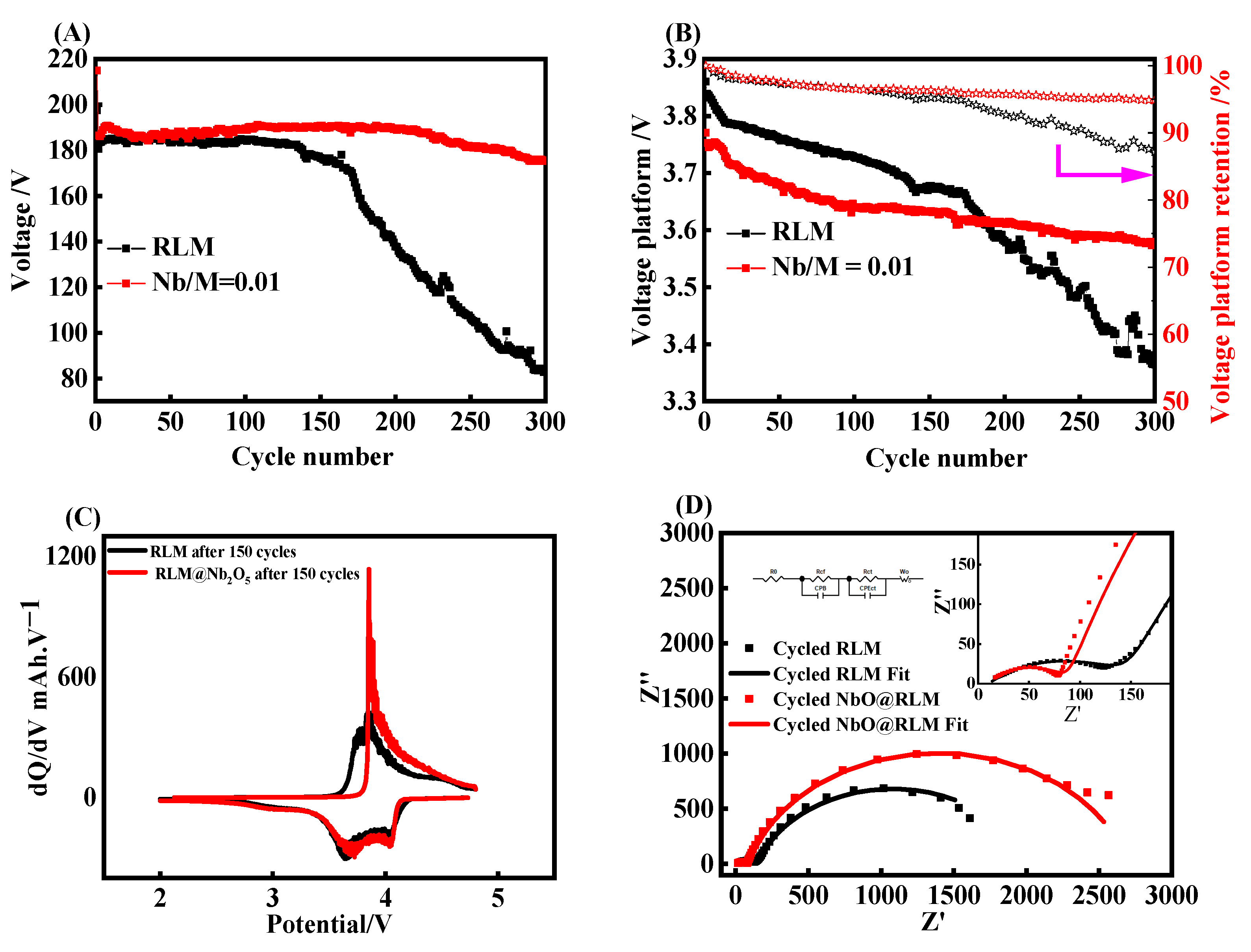
Figure 1. The initial charge−discharge curves (AG), discharge capacity and Coulombic efficiency (H), and dQ/dV curves for different ratios of Nb:M (I,J).
Molecules 28 03890 g001
Figure 2. The cycling life curves (A), the platform of discharge (B), and dQ/dV curves (C,D) of the 8th cycle for different coating ratios of RLM@Nb2O5.
Molecules 28 03890 g002
Figure 3. The cycling life curves (A), platform of discharge (B), charge and discharge curves and dQ/dV curves of the 1st cycle (CE) and 8th cycle (FH) of the samples obtained at 550 °C, 600 °C, 650 °C, 700 °C, 750 °C, 800 °C, 850 °C, and 900 °C, respectively.
Molecules 28 03890 g003
Figure 4. XRD patterns (A) and Nb XPS pattern (B) of RLM@Nb2O5.
Molecules 28 03890 g004
Figure 5. SEM images of RLM-1 (A), all-element mapping images of RLM-1 (B), O-element mapping images (C), Mn- and Ni-element mapping images (D), SEM images of RLM@Nb2O5 (E), all-element mapping images of RLM-1 (F), O- and Nb-element mapping images (G), Mn- and Ni-element mapping images (H).
Molecules 28 03890 g005
Figure 6. The cycling life curves (A), voltage platform of discharge and voltage retention (B), dQ/dV curves of the 150th cycle (C), and impedance diagram after 300 cycles (D).
Molecules 28 03890 g006
Figure 7. TEM of RLM-1 (A) and RLM@Nb2O5 (C), and RLM-1 (B) and RLM@Nb2O5 after 300 cycles (D).
Molecules 28 03890 g007
Figure 8. The SEM images of RLM-1 (A) and RLM@Nb2O5 (B), and RLM-1 (C) and RLM@Nb2O5 after 300 cycles (D).
Molecules 28 03890 g008
Figure 9. XPS spectra of RLM-1 and RLM@Nb2O5: C 1s (A), O 1s (B), F 1s (C), and Nb (D).
Molecules 28 03890 g009
Table 1. Comparison of resistance sections of RLM and RLM@Nb2O5.
RLMRLM @ Nb2O5
Rs/(Ω)10.469.675
Rf/(Ω)143.480.13
CPE1CPE1-T/(F)1.4348 × 10−44.4665 × 10−5
CPE1-P/(F)0.467650.57493
Rct/(Ω)18562610
CPE2CPE2-T/(F)1.9901 × 10−26.5415 × 10−4
CPE2-P/(F)0.804590.83649
Disclaimer/Publisher’s Note: The statements, opinions and data contained in all publications are solely those of the individual author(s) and contributor(s) and not of MDPI and/or the editor(s). MDPI and/or the editor(s) disclaim responsibility for any injury to people or property resulting from any ideas, methods, instructions or products referred to in the content.

