

Supercapatteries as Hybrid Electrochemical Energy Storage Devices: Current Status and Future Prospects


Abstract
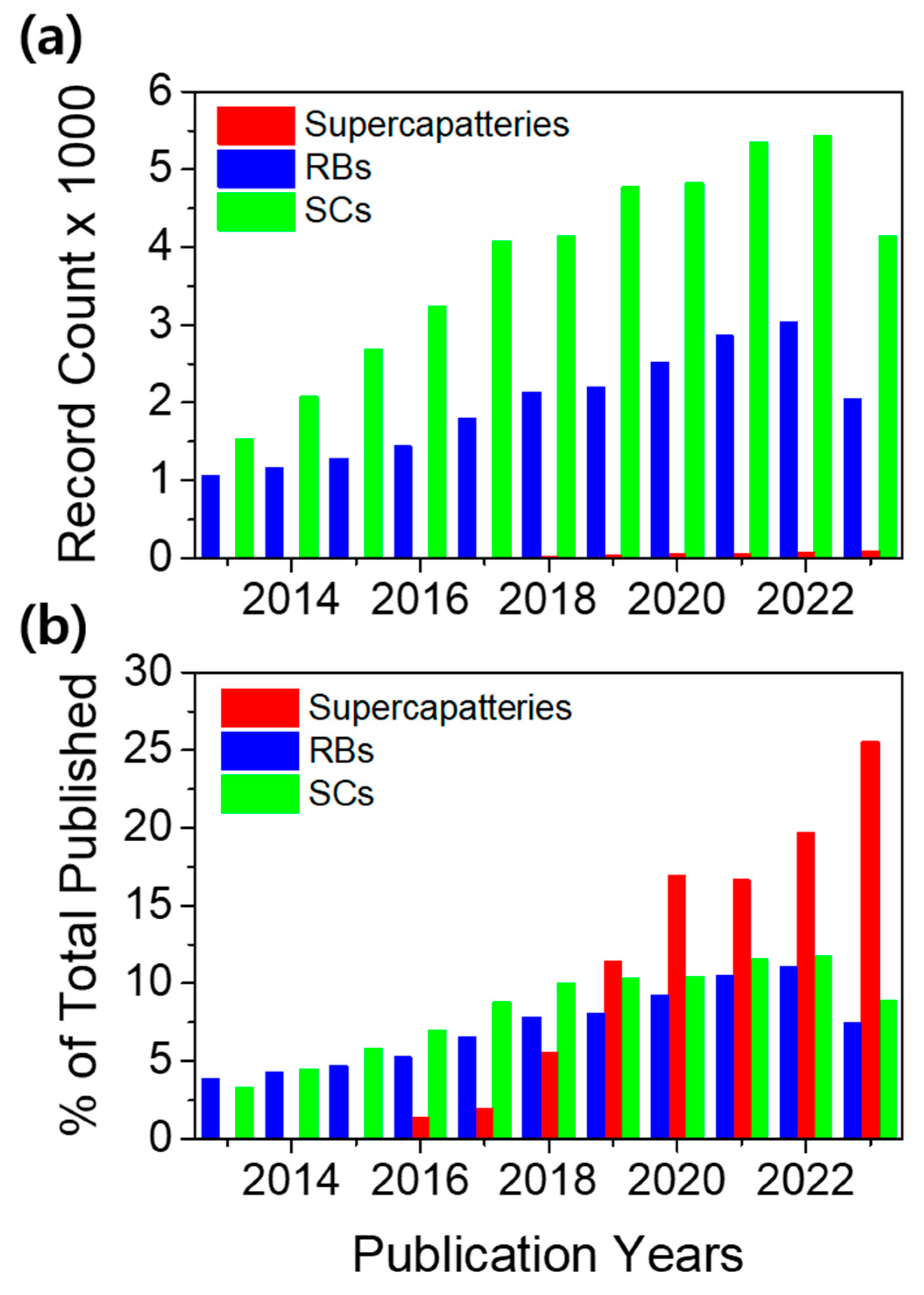
1. Introduction
2. Some Important Definitions and Parameters of EES
2.1. Capacitance and Charge of an Electrode
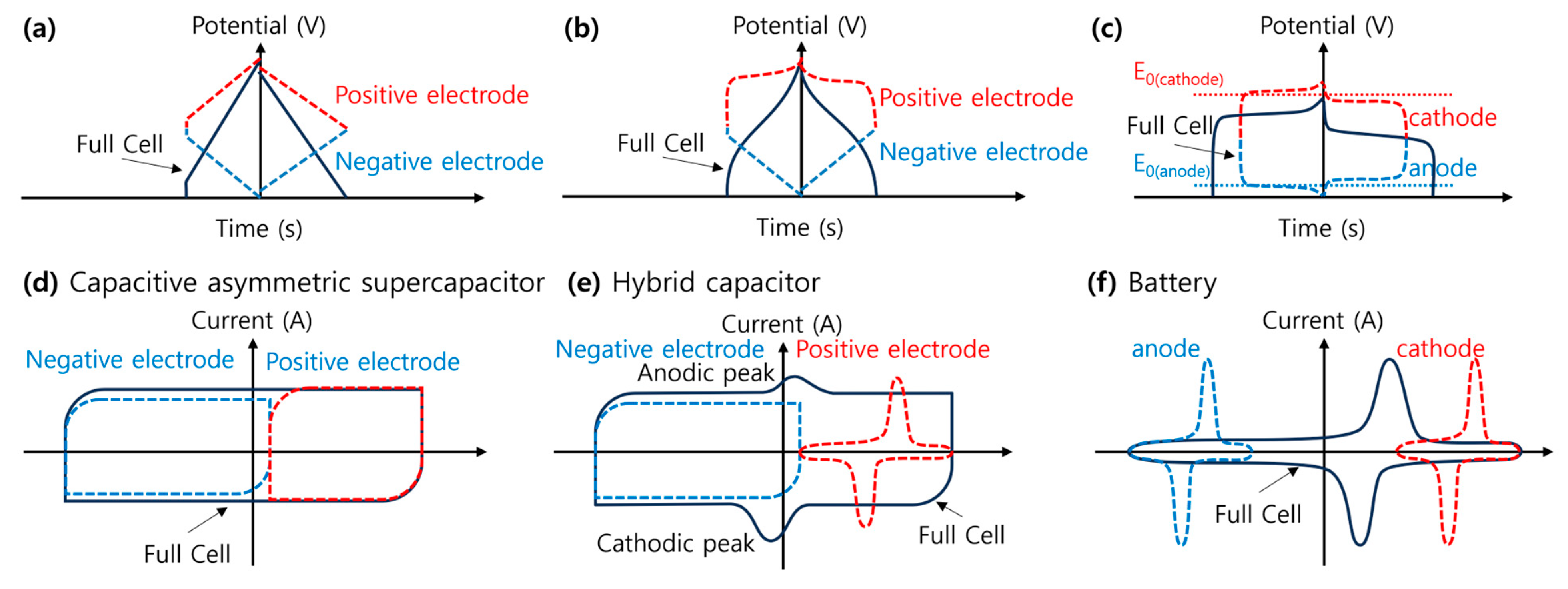
2.2. Galvanostatic Charge–Discharge (GCD)
2.3. Cyclic Voltammetry (CV)
2.4. Mass and Charge Balance
2.5. Energy Density
2.6. Power Density
2.7. Ragone Plots
2.8. Capacitive and Diffusive Storage
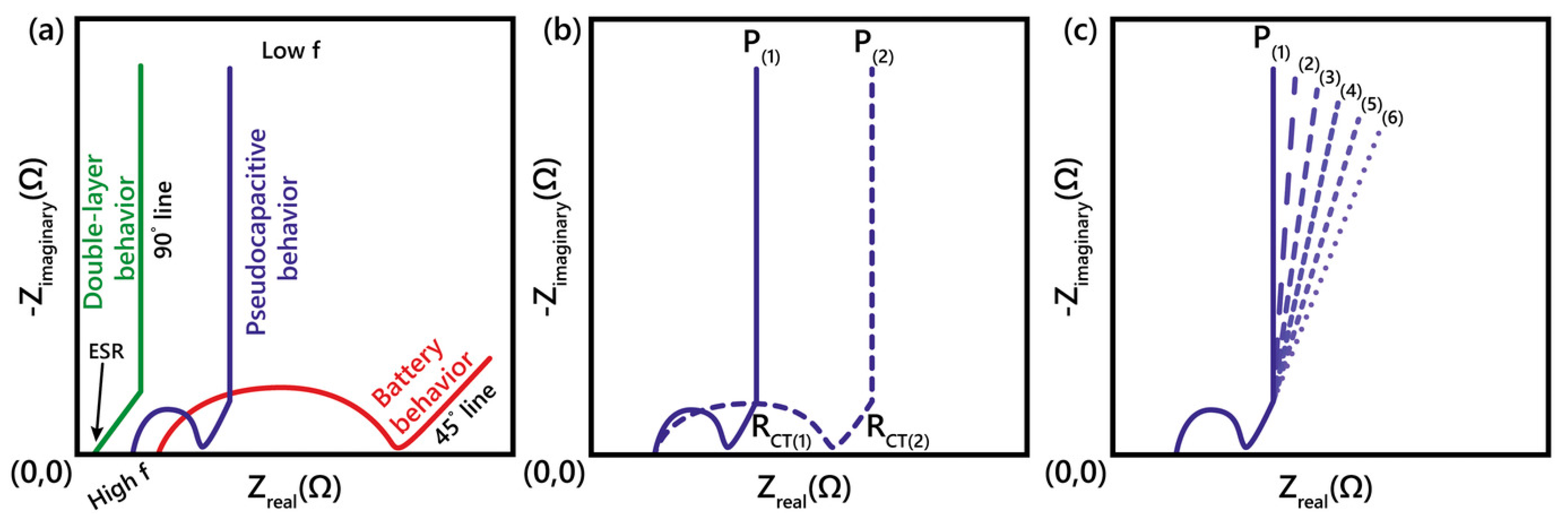
2.9. Electrochemical Impedance Spectroscopy (EIS)
2.10. Notation for Electrodes of EES
3. Electrochemical Energy Storage (EES) Devices
3.1. Supercapacitors (SCs)
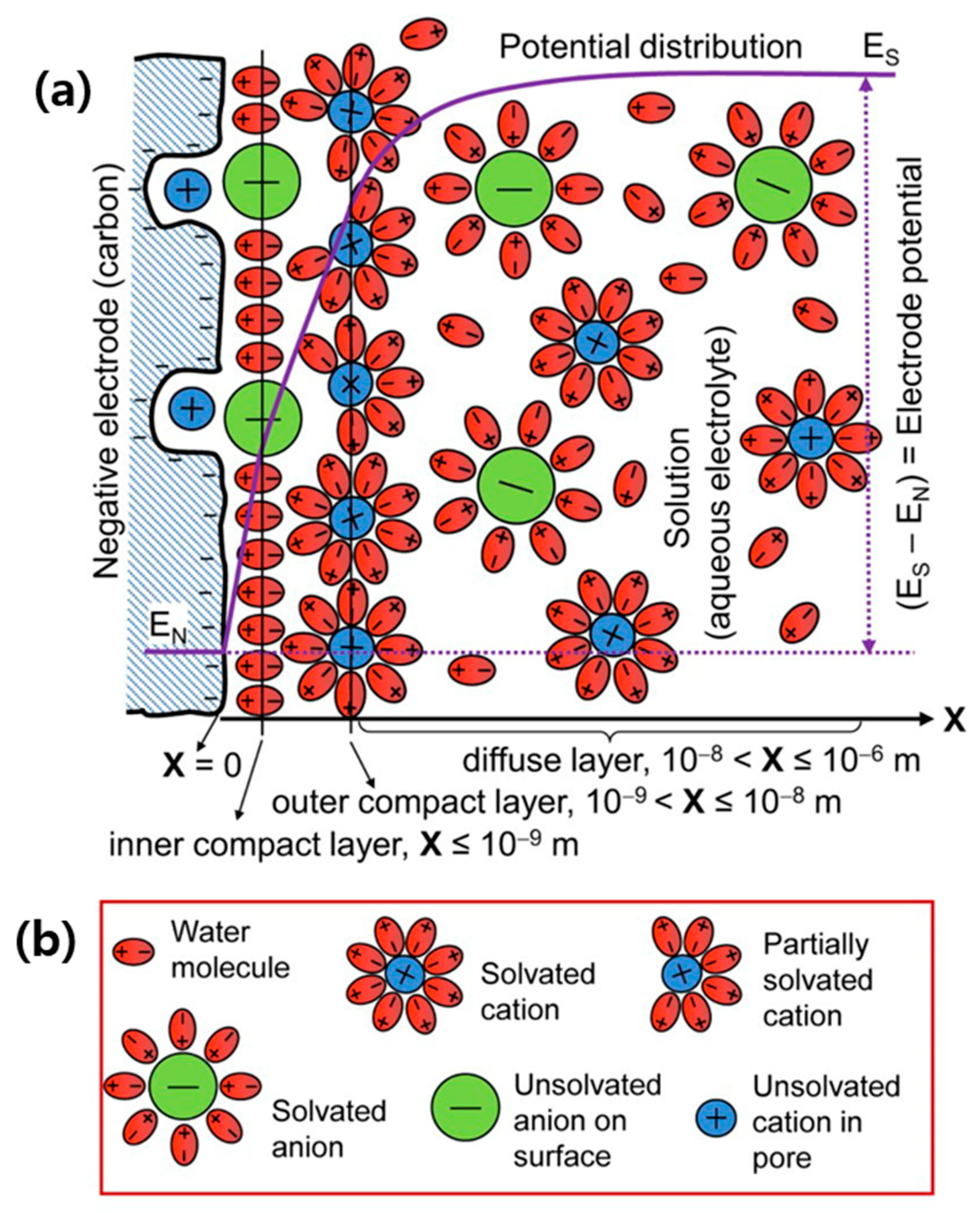
3.2. Electrical Double-Layer Capacitors (EDLCs)
3.3. Pseudocapacitors (PCs)
3.4. Hybrid Supercapacitors (HSCs)
3.5. Rechargeable Batteries (RBs)
3.6. Supercapatteries
3.7. Electrode and Electrolyte Materials in Supercapatteries

| Device Configuration | Electrolyte | Electrode Type | Energy Density (Wh/kg) | Power Density (W/kg) | Publication Year | Reference |
|---|---|---|---|---|---|---|
| CeNiO3/Ni foam (symmetric) | 6M KOH | (+)RB//RB(−) | 38.70 28.41 | 774.81 7750 | 2022 | [78] |
| CeNiO3/Ni foam (symmetric) | 3M KOH | (+)RB//RB(−) | 43.45 | 800 | 2022 | [85] |
| BiOI-Bi9I2/Ni foam (symmetric) | 6M KOH | (+)RB//RB(−) | 38.2 | 2280.4 | 2020 | [63] |
| β-NiMoO4/Ni foam (symmetric) | 3M KOH | (+)RB//RB(−) | 35.8 21.3 | 981.56 19,282.4 | 2020 | [64] |
| Ni(py-TTF-py)(BPDC)/Ni foam//AC/NI foam | 6M KOH | (+)RB//ED(−) | 90.3 47.2 | 1180 10,400 | 2023 | [86] |
| AgSr-Phosphate/Ni foam//CNT/Ni foam | 1M KOH | (+)RB//ED(−) | 55.02 42.37 | 741.54 9075 | 2023 | [87] |
| Mxene/Ni foam//AC/Ni foam | 1M KOH | (+)RB//ED(−) | 68.8 | 1120 | 2023 | [88] |
| NiS/Ni foam//AC/Ni foam | 1M KOH | (+)RB//ED(−) | 61.76 | 1275 | 2023 | [89] |
| Fe2O3-α-Ni(OH)2/Ni foam//AC/Ni foam | 1M KOH | (+)RB//ED(−) | 44.51 | 2465 | 2023 | [90] |
| CoMnS-rGO/Ni foam//AC/Ni foam | 1M KOH | (+)RB//ED(−) | 45.6 | 2880 | 2023 | [91] |
| CoCuP/Ni foam//O, N, S-AC/Ni foam | 6M KOH | (+)RB//ED(−) | 37.3 18.4 | 915 12,308.8 | 2023 | [79] |
| Fe-Mg MOF/Ni foam//AC/Ni foam | KOH | (+)RB//ED(−) | 57 | 2393 | 2023 | [92] |
| Ag2Co3(PO6)2/Ni foam//CNT/Ni foam | 1M KOH | (+)RB//ED(−) | 40.92 33.26 | 1237.5 4125 | 2022 | [93] |
| SrS/Ni foam//AC/Ni foam | KOH | (+)RB//ED(−) | 44.39 12.9 | 595 8400 | 2022 | [94] |
| CeO2-ZnO-ZnWO4-AC/Ni foam//AC/Ni foam | 2M KOH | (+)RB//ED(−) | 56.92 | 2000 | 2022 | [95] |
| MnS/Ni foam//AC/Ni foam | KOH | (+)RB//ED(−) | 127.5 | 2550 | 2022 | [96] |
| WS/Ni foam//AC/Ni foam | 1M KOH | (+)RB//ED(−) | 45.2 | 608 | 2022 | [97] |
| NiCo LDH/Ni foam//AC/Ni foam | 6M KOH | (+)RB//ED(−) | 20.5 9.01 | 774.5 8522.7 | 2022 | [69] |
| NiCo2S4-graphene/Ni foam//AC-graphene/Ni foam | 4M KOH + carboxymethyl cellulose | (+)RB//ED(−) | 80 | 4000 | 2022 | [98] |
| LaMnO3/carbon cloth//rGO/carbon cloth | 1M KOH | (+)RB//ED(−) | 154 72 | 324 14,700 | 2022 | [76] |
| LaMnO3/carbon cloth//rGO/carbon cloth | 1M NaClO4 | (+)RB//ED(−) | 236 | 3630 | 2022 | [76] |
| LaMnO3/carbon cloth//rGO/carbon cloth | 2M LiPF6 | (+)RB//ED(−) | 123 | 1430 | 2022 | [76] |
| NiFe-Phosphate/Ni foam//AC/Ni foam | 1M KOH | (+)RB//ED(−) | 45.6 | 2250 | 2022 | [99] |
| 2D MoO3-S4-C/Ni foam//rGO/Ni foam | 6M KOH | (+)RB//ED(−) | 129.6 | 11,600 | 2021 | [77] |
| Cu-MOF-PANI-rGO-Ag/Ni foam//AC/Ni foam | 1M KOH | (+)RB//ED(−) | 52 27.2 | 1192 10,200 | 2021 | [100] |
| Co0.5Mn0.5S/Ni foam//AC/Ni foam | 1M KOH | (+)RB//ED(−) | 61.34 9.92 | 850 8500 | 2021 | [101] |
| VSB-5-rGO/Ni foam//AC/Ni foam | 1M NaOH | (+)RB//ED(−) | 80.5 | 2216.5 | 2021 | [102] |
| FeCoCuS2/Ni foam//AC/Ni foam | 3M KOH | (+)RB//ED(−) | 48.2 27.2 | 820.1 25,700.2 | 2021 | [70] |
| Co0.125Cu0.375Mn0.500S/Ni foam//AC/Ni foam | 1M KOH | (+)RB//ED(−) | 88.71 20 | 320 8000 | 2021 | [71] |
| Co3(PO4)2/Cu/Ni foam//AC/Ni foam | 1M KOH | (+)RB//ED(−) | 62.6 11.8 | 425 7924 | 2021 | [103] |
| NiMn(PO4)2-PANI/Ni foam//AC/Ni foam | 1M KOH | (+)RB//ED(−) | 71.3 | 340 | 2021 | [104] |
| Co3(PO4)2/Ni foam//AC/Ni foam | 1M KOH | (+)RB//ED(−) | 34.8 10.0 | 425 6800 | 2021 | [105] |
| MnCo2S4-Mxene/Ni foam//AC/Ni foam | 3M KOH | (+)RB//ED(−) | 25.6 12.44 | 400 6400 | 2021 | [106] |
| Co3(PO4)2/Ag/Ni foam//AC/Ni foam | 1M KOH | (+)RB//ED(−) | 65.8 | 510 | 2021 | [107] |
| Ni0.75Mn0.25(PO4)2/Ni foam//AC/Ni foam | 1M KOH | (+)RB//ED(−) | 64.2 | 340 | 2021 | [108] |
| Co0.125Cu0.375Mn0.500(PO4)2/Ni foam//AC/Ni foam | 1M KOH | (+)RB//ED(−) | 56 16.88 | 800 6420 | 2021 | [109] |
| Trypan blue-Ni-MOF/Ni foam//Azure A-graphene aerogel/Ni foam | 3M KOH | (+)RB//ED(−) | 66.55 11.11 | 349 4450 | 2021 | [110] |
| NiO@CuCo2O4/MoNi/Ni foam//AC/Ni foam | 2M KOH | (+)RB//ED(−) | 80.6 63.8 | 692.8 14,000 | 2021 | [111] |
| Zn0.5Co0.5S/Ni foam//AC/Ni foam | 2M KOH | (+)RB//ED(−) | 49 23 | 957 9413 | 2021 | [112] |
| Co0.5Cu0.5Mn(PO4)2/Ni foam//AC/Ni foam | 1M KOH | (+)RB//ED(−) | 55 19 | 800 6400 | 2021 | [113] |
| Ni-Co-Bi double hydroxide/Ni-Co-B/Ni foam//AC/Ni foam | 2M KOH | (+)RB//ED(−) | 62.8 | 800 | 2020 | [114] |
| Phosphate ion-functionalized NiO (P-NiO)/Ni foam//AC/Ni foam | 3M KOH | (+)RB//ED(−) | 53.4 24.7 | 800 12,000 | 2020 | [65] |
| Sr3P2-PANI/Ni foam//AC/Ni foam | 1M KOH | (+)RB//ED(−) | 28.9 10.95 | 1020 5100 | 2020 | [73] |
| Zn0.5CoO0.5Mn(PO4)2/Ni foam//AC/Ni foam | 1M KOH | (+)RB//ED(−) | 45.45 6.86 | 425 4250 | 2020 | [66] |
| Co3(PO4)2/Ni-Co-O/Ni foam//Fe2P/graphene hydrogel/Ni foam | PVA-KOH | (+)RB//ED(−) | 95 18 | 400 4000 | 2020 | [67] |
| Co0.5Ni0.5WO4/Ni foam//AC/Ni foam | 2M KOH | (+)RB//ED(−) | 42.2 | 1047.7 | 2020 | [68] |
| Co-MOF-PANI/Ni foam//AC/Ni foam | 1M KOH | (+)RB//ED(−) | 23.11 8.906 | 1600 6400 | 2020 | [72] |
| WO3-WS2-MWCNT/Ni foam//AC/Ni foam | 3M KOH | (+)PC//ED(−) | 86 24 | 848 11,828 | 2023 | [115] |
| Ni-Co-Mg MOF/MoS2/Ni foam//AC/Ni foam | 1M KOH | (+)PC//ED(−) | 107.32 | 1350 | 2023 | [116] |
| NH4MnPO4@Graphene QD/Graphite//rGO/Graphite | 3M H2SO4 3M H2SO4 + 0.025M (KI/VOSO4) | (+)PC//ED(−) | 199 311 | 450 450 | 2022 | [82] |
| Ni3(PO4)2-MWCNTs/Ni foam//AC/Ni foam | (+)PC//ED(−) | 94.4 24.82 | 340 10,200 | 2022 | [117] | |
| Mn-V-Sn oxyhydroxide/Ni foam//N-carbon/Ni foam | 1M KOH | (+)PC//ED(−) | 70.6 17.1 | 1372.4 18,861.3 | 2022 | [118] |
| NH4OH-ZIF/Ni foam//GO/Ni foam | 6M KOH | (+)PC//ED(−) | 4.16 | 20,000 | 2022 | [119] |
| CoS-Co3(PO4)2/Ni foam//AC/Ni foam | 1M KOH | (+)PC//ED(−) | 34.68 63.93 | 13,600 850 | 2021 | [120] |
| Fe3O4@N-carbon-rGO/Ni foam//rGO/Ni foam | 6M KOH | (+)PC//ED(−) | 46 10 | 750 7500 | 2021 | [121] |
| MWCNT-NiMnPO4/Ni foam//AC/Ni foam | 2M KOH | (+)PC//ED(−) | 698 43 | 78 5780 | 2020 | [74] |
| P-NiCoB/Ni foam//rGO/Ni foam | 2M KOH | (+)RB//PC(−) | 63.125 41.56 | 750 15,000 | 2023 | [80] |
| CoMn2O4/N-graphene/Ni foam//N-graphene/Ni foam | PVA-KOH | (+)RB//PC(−) | 44.1 20.3 | 992.6 12,430 | 2021 | [122] |
| graphitic carbon nitride (g-C3N4)-BiVO4/Graphite paper (symmetric) | 3.5M KOH | (+)PC//PC(−) | 61 7.2 | 1996 16,200 | 2020 | [75] |
| Zn-Carbon cloths//S/P doped carbon (S/p-C)/graphite rod | 0.5M K2SO4 1M KBr | (+)PC//PC(−) | 270 181 | 185 9300 | 2020 | [81] |
3.8. Performance and Experimental Evaluation of Supercapatteries
3.9. Classification of EES Devices
4. Summary and Perspective
Author Contributions
Funding
Conflicts of Interest
References
- Gabric, A.J. The Climate Change Crisis: A Review of Its Causes and Possible Responses. Atmosphere 2023, 14, 1081. [Google Scholar] [CrossRef]
- Abbass, K.; Qasim, M.Z.; Song, H.; Murshed, M.; Mahmood, H.; Younis, I. A review of the global climate change impacts, adaptation, and sustainable mitigation measures. Environ. Sci. Pollut. Res. 2022, 29, 42539–42559. [Google Scholar] [CrossRef] [PubMed]
- Dutta, A.; Mitra, S.; Basak, M.; Banerjee, T. A comprehensive review on batteries and supercapacitors: Development and challenges since their inception. Energy Storage 2023, 5, e339. [Google Scholar] [CrossRef]
- Goodenough, J.B.; Park, K.-S. The Li-Ion Rechargeable Battery: A Perspective. J. Am. Chem. Soc. 2013, 135, 1167–1176. [Google Scholar] [CrossRef]
- Choi, H.S.; Park, C.R. Theoretical guidelines to designing high performance energy storage device based on hybridization of lithium-ion battery and supercapacitor. J. Power Sources 2014, 259, 1–14. [Google Scholar] [CrossRef]
- Kiai, M.S.; Eroglu, O.; Aslfattahi, N. Metal-Ion Batteries: Achievements, Challenges, and Prospects. Crystals 2023, 13, 1002. [Google Scholar] [CrossRef]
- Verma, J.; Kumar, D. Metal-ion batteries for electric vehicles: Current state of the technology, issues and future perspectives. Nanoscale Adv. 2021, 3, 3384–3394. [Google Scholar] [CrossRef]
- Chatterjee, D.P.; Nandi, A.K. A review on the recent advances in hybrid supercapacitors. J. Mater. Chem. A Mater. 2021, 9, 15880–15918. [Google Scholar] [CrossRef]
- Gao, D.; Luo, Z.; Liu, C.; Fan, S. A survey of hybrid energy devices based on supercapacitors. Green Energy Environ. 2023, 8, 972–988. [Google Scholar] [CrossRef]
- Yu, A.; Chabot, V.; Zhang, J. Electrochemical Supercapacitors for Energy Storage and Delivery Fundamentals and Applications; Taylor & Francis: Abingdon-on-Thames, UK, 2013. [Google Scholar]
- Simon, P.; Gogotsi, Y. Materials for electrochemical capacitors. Nat. Mater. 2008, 7, 845–854. [Google Scholar] [CrossRef]
- Iqbal, M.Z.; Faisal, M.M.; Ali, S.R. Integration of supercapacitors and batteries towards high-performance hybrid energy storage devices. Int. J. Energy Res. 2021, 45, 1449–1479. [Google Scholar] [CrossRef]
- Xia, L.; Tang, B.; Wei, J.; Zhou, Z. Recent Advances in Alkali Metal-Ion Hybrid Supercapacitors. Batter. Supercaps 2021, 4, 1108–1121. [Google Scholar] [CrossRef]
- Majumdar, D.; Mandal, M.; Bhattacharya, S.K. Journey from supercapacitors to supercapatteries: Recent advancements in electrochemical energy storage systems. Emergent Mater. 2020, 3, 347–367. [Google Scholar] [CrossRef]
- Yu, L.; Chen, G.Z. Supercapatteries as High-Performance Electrochemical Energy Storage Devices. Electrochem. Energy Rev. 2020, 3, 271–285. [Google Scholar] [CrossRef]
- Prajapati, M.; Singh, V.; Jacob, M.V.; Kant, C.R. Recent advancement in metal-organic frameworks and composites for high-performance supercapatteries. Renew. Sustain. Energy Rev. 2023, 183, 113509. [Google Scholar] [CrossRef]
- Bard, A.J.; Faulkner, L.R.; White, H.S. Electrochemical Methods: Fundamentals and Applications; John Wiley & Sons: Hoboken, NJ, USA, 2022. [Google Scholar]
- Chen, G.Z. Supercapacitor and supercapattery as emerging electrochemical energy stores. Int. Mater. Rev. 2017, 62, 173–202. [Google Scholar] [CrossRef]
- Guan, L.; Yu, L.; Chen, G.Z. Capacitive and non-capacitive faradaic charge storage. Electrochim. Acta 2016, 206, 464–478. [Google Scholar] [CrossRef]
- Shao, Y.; El-Kady, M.F.; Sun, J.; Li, Y.; Zhang, Q.; Zhu, M.; Wang, H.; Dunn, B.; Kaner, R.B. Design and Mechanisms of Asymmetric Supercapacitors. Chem Rev. 2018, 118, 9233–9280. [Google Scholar] [CrossRef]
- Mathis, T.S.; Kurra, N.; Wang, X.; Pinto, D.; Simon, P.; Gogotsi, Y. Energy Storage Data Reporting in Perspective—Guidelines for Interpreting the Performance of Electrochemical Energy Storage Systems. Adv. Energy Mater. 2019, 9, 1902007. [Google Scholar] [CrossRef]
- Sarker, S.; Seo, H.W.; Jin, Y.-K.; Lee, K.-S.; Lee, M.; Kim, D.M. On the Hysteresis of Current Density-Voltage Curves of Dye-sensitized Solar Cells. Electrochim. Acta 2015, 182, 493–499. [Google Scholar] [CrossRef]
- Kannadasan, K.; Devi, V.S.; Archana, S.; Thomas, P.; Elumalai, P. Deconvolution of capacitive and diffusive charge/lithium storage in lyophilized NiCo2S4-NiCo2O4 composite for supercapattery and lithium-ion battery. New J. Chem. 2023, 47, 13963–13978. [Google Scholar] [CrossRef]
- Akinwolemiwa, B.; Peng, C.; Chen, G.Z. Redox Electrolytes in Supercapacitors. J. Electrochem. Soc. 2015, 162, A5054–A5059. [Google Scholar] [CrossRef]
- Gogotsi, Y.; Simon, P. True Performance Metrics in Electrochemical Energy Storage. Science 2011, 334, 917–918. [Google Scholar] [CrossRef] [PubMed]
- Sarker, S.; Ahammad, A.J.S.; Seo, H.W.; Kim, D.M. Electrochemical Impedance Spectra of Dye-Sensitized Solar Cells: Fundamentals and Spreadsheet Calculation. Int. J. Photoenergy 2014, 2014, 851705. [Google Scholar] [CrossRef]
- Brezesinski, T.; Wang, J.; Tolbert, S.H.; Dunn, B. Ordered mesoporous α-MoO3 with iso-oriented nanocrystalline walls for thin-film pseudocapacitors. Nat. Mater. 2010, 9, 146–151. [Google Scholar] [CrossRef]
- Itagaki, M.; Suzuki, S.; Shitanda, I.; Watanabe, K. Electrochemical Impedance and Complex Capacitance to Interpret Electrochemical Capacitor. Electrochemistry 2007, 75, 649–655. [Google Scholar] [CrossRef]
- Winter, M.; Brodd, R.J. What Are Batteries, Fuel Cells, and Supercapacitors? Chem. Rev. 2004, 104, 4245–4270. [Google Scholar] [CrossRef]
- Yu, L.; Chen, G.Z. Redox electrode materials for supercapatteries. J. Power Sources 2016, 326, 604–612. [Google Scholar] [CrossRef]
- Akinwolemiwa, B.; Chen, G.Z. Fundamental consideration for electrochemical engineering of supercapattery. J. Braz. Chem. Soc. 2018, 29, 960–972. [Google Scholar] [CrossRef]
- Dsoke, S.; Pfeifer, K.; Zhao, Z. The role of nanomaterials for supercapacitors and hybrid devices. In Frontiers of Nanoscience; Elsevier Ltd.: Amsterdam, The Netherlands, 2021; pp. 99–136. [Google Scholar] [CrossRef]
- Gogotsi, Y.; Penner, R.M. Energy Storage in Nanomaterials–Capacitive, Pseudocapacitive, or Battery-like? ACS Nano 2018, 12, 2081–2083. [Google Scholar] [CrossRef]
- Akinwolemiwa, B.; Wei, C.; Chen, G.Z. Mechanisms and Designs of Asymmetrical Electrochemical Capacitors. Electrochim. Acta 2017, 247, 344–357. [Google Scholar] [CrossRef]
- Zhao, J.; Burke, A.F. Review on supercapacitors: Technologies and performance evaluation. J. Energy Chem. 2021, 59, 276–291. [Google Scholar] [CrossRef]
- Sinha, P.; Kar, K.K. Introduction to Supercapacitors. In Handbook of Nanocomposite Supercapacitor Materials II; Kar, K.K., Ed.; Springer: Berlin/Heidelberg, Germany, 2020; pp. 1–28. [Google Scholar] [CrossRef]
- Iqbal, M.Z.; Aziz, U. Supercapattery: Merging of battery-supercapacitor electrodes for hybrid energy storage devices. J. Energy Storage 2022, 46, 103823. [Google Scholar] [CrossRef]
- Poonam, K.; Sharma, A.; Arora, S.K. Tripathi, Review of supercapacitors: Materials and devices. J. Energy Storage 2019, 21, 801–825. [Google Scholar] [CrossRef]
- Augustyn, V.; Simon, P.; Dunn, B. Pseudocapacitive oxide materials for high-rate electrochemical energy storage. Energy Environ. Sci. 2014, 7, 1597. [Google Scholar] [CrossRef]
- Liu, Y.; Jiang, S.P.; Shao, Z. Intercalation pseudocapacitance in electrochemical energy storage: Recent advances in fundamental understanding and materials development. Mater. Today Adv. 2020, 7, 100072. [Google Scholar] [CrossRef]
- Jiang, Y.; Liu, J. Definitions of Pseudocapacitive Materials: A Brief Review. Energy Environ. Mater. 2019, 2, 30–37. [Google Scholar] [CrossRef]
- Conway, B.E. Two-dimensional and quasi-two-dimensional isotherms for Li intercalation and upd processes at surfaces. Electrochim. Acta 1993, 38, 1249–1258. [Google Scholar] [CrossRef]
- Herrero, E.; Buller, L.J.; Abruña, H.D. Underpotential Deposition at Single Crystal Surfaces of Au, Pt, Ag and Other Materials. Chem. Rev. 2001, 101, 1897–1930. [Google Scholar] [CrossRef]
- Park, H.W.; Roh, K.C. Recent advances in and perspectives on pseudocapacitive materials for Supercapacitors—A review. J. Power Sources 2023, 557, 232558. [Google Scholar] [CrossRef]
- Barik, R.; Ingole, P.P. Challenges and prospects of metal sulfide materials for supercapacitors. Curr. Opin. Electrochem. 2020, 21, 327–334. [Google Scholar] [CrossRef]
- Brousse, T.; Bélanger, D.; Long, J.W. To Be or Not To Be Pseudocapacitive? J. Electrochem. Soc. 2015, 162, A5185–A5189. [Google Scholar] [CrossRef]
- Lamba, P.; Singh, P.; Singh, P.; Singh, P.; Bharti; Kumar, A.; Gupta, M.; Kumar, Y. Recent advancements in supercapacitors based on different electrode materials: Classifications, synthesis methods and comparative performance. J. Energy Storage 2022, 48, 103871. [Google Scholar] [CrossRef]
- Olabi, A.G.; Abbas, Q.; Shinde, P.A.; Abdelkareem, M.A. Rechargeable batteries: Technological advancement, challenges, current and emerging applications. Energy 2023, 266, 126408. [Google Scholar] [CrossRef]
- Khan, S.A.; Ali, S.; Saeed, K.; Usman, M.; Khan, I. Advanced cathode materials and efficient electrolytes for rechargeable batteries: Practical challenges and future perspectives. J. Mater. Chem. A Mater. 2019, 7, 10159–10173. [Google Scholar] [CrossRef]
- Liu, Q.; Wang, H.; Jiang, C.; Tang, Y. Multi-ion strategies towards emerging rechargeable batteries with high performance. Energy Storage Mater. 2019, 23, 566–586. [Google Scholar] [CrossRef]
- Halford, B. Lithium-Ion Battery Pioneers nab 2019 Nobel Prize in Chemistry. 2019. Available online: https://cen.acs.org/people/nobel-prize/Li-ion-batteries-win-2019-Nobel-Prize-in-Chemistry/97/web/2019/10 (accessed on 25 November 2023).
- Chen, W.; Liang, J.; Yang, Z.; Li, G. A Review of Lithium-Ion Battery for Electric Vehicle Applications and Beyond. Energy Procedia 2019, 158, 4363–4368. [Google Scholar] [CrossRef]
- Nzereogu, P.U.; Omah, A.D.; Ezema, F.I.; Iwuoha, E.I.; Nwanya, A.C. Anode materials for lithium-ion batteries: A review. Appl. Surf. Sci. Adv. 2022, 9, 100233. [Google Scholar] [CrossRef]
- Woo, S.-W.; Dokko, K.; Nakano, H.; Kanamura, K. Bimodal Porous Carbon as a Negative Electrode Material for Lithium-Ion Capacitors. Electrochemistry 2007, 75, 635–640. [Google Scholar] [CrossRef]
- Wang, H.; Zhu, C.; Chao, D.; Yan, Q.; Fan, H.J. Nonaqueous Hybrid Lithium-Ion and Sodium-Ion Capacitors. Adv. Mater. 2017, 29, 1702093. [Google Scholar] [CrossRef]
- Chen, Z.-K.; Lang, J.-W.; Liu, L.-Y.; Kong, L.-B. Preparation of a NbN/graphene nanocomposite by solution impregnation and its application in high-performance Li-ion hybrid capacitors. RSC Adv. 2017, 7, 19967–19975. [Google Scholar] [CrossRef]
- Arnaiz, M.; Gómez-Cámer, J.L.; Ajuria, J.; Bonilla, F.; Acebedo, B.; Jáuregui, M.; Goikolea, E.; Galceran, M.; Rojo, T. High Performance Titanium Antimonide TiSb2 Alloy for Na-Ion Batteries and Capacitors. Chem. Mater. 2018, 30, 8155–8163. [Google Scholar] [CrossRef]
- Shimizu, W.; Makino, S.; Takahashi, K.; Imanishi, N.; Sugimoto, W. Development of a 4.2 V aqueous hybrid electrochemical capacitor based on MnO2 positive and protected Li negative electrodes. J. Power Sources 2013, 241, 572–577. [Google Scholar] [CrossRef]
- Makino, S.; Shinohara, Y.; Ban, T.; Shimizu, W.; Takahashi, K.; Imanishi, N.; Sugimoto, W. 4 V class aqueous hybrid electrochemical capacitor with battery-like capacity. RSC Adv. 2012, 2, 12144. [Google Scholar] [CrossRef]
- Hu, D.; Peng, C.; Chen, G.Z. Electrodeposition of Nonconducting Polymers: Roles of Carbon Nanotubes in the Process and Products. ACS Nano 2010, 4, 4274–4282. [Google Scholar] [CrossRef] [PubMed]
- Simon, P.; Gogotsi, Y.; Dunn, B. Where Do Batteries End and Supercapacitors Begin? Science 2014, 343, 1210–1211. [Google Scholar] [CrossRef]
- Balasubramaniam, S.; Mohanty, A.; Balasingam, S.K.; Kim, S.J.; Ramadoss, A. Comprehensive Insight into the Mechanism, Material Selection and Performance Evaluation of Supercapatteries. Nanomicro Lett. 2020, 12, 85. [Google Scholar] [CrossRef]
- Park, S.; Shinde, N.M.; Shinde, P.V.; Lee, D.; Yun, J.M.; Kim, K.H. Chemically grown bismuth-oxy-iodide (BiOI/Bi9I2) nanostructure for high performance battery-type supercapacitor electrodes. Dalton Trans. 2020, 49, 774–780. [Google Scholar] [CrossRef]
- Padmanathan, N.; Shao, H.; Razeeb, K.M. Honeycomb micro/nano-architecture of stable β-NiMoO4 electrode/catalyst for sustainable energy storage and conversion devices. Int. J. Hydrogen Energy 2020, 45, 30911–30923. [Google Scholar] [CrossRef]
- Kang, M.; Zhou, H.; Qin, B.; Zhao, N.; Lv, B. Ultrathin nanosheet-assembled, phosphate ion-functionalized NiO microspheres as efficient supercapacitor materials. ACS Appl. Energy Mater. 2020, 3, 9980–9988. [Google Scholar] [CrossRef]
- Iqbal, M.Z.; Khan, J.; Awan, H.T.A.; Alzaid, M.; Afzal, A.M.; Aftab, S. Cobalt-manganese-zinc ternary phosphate for high performance supercapattery devices. Dalton Trans. 2020, 49, 16715–16727. [Google Scholar] [CrossRef] [PubMed]
- Yan, T.; Feng, H.; Ma, X.; Han, L.; Zhang, L.; Cao, S. Regulating the electrochemical behaviours of a hierarchically structured Co3(PO4)2/Ni-Co-O for a high-performance all-solid-state supercapacitor. Dalton Trans. 2020, 49, 10621–10630. [Google Scholar] [CrossRef] [PubMed]
- Huang, B.; Wang, H.; Liang, S.; Qin, H.; Li, Y.; Luo, Z.; Zhao, C.; Xie, L.; Chen, L. Two-dimensional porous cobalt–nickel tungstate thin sheets for high performance supercapattery. Energy Storage Mater. 2020, 32, 105–114. [Google Scholar] [CrossRef]
- Thondaiman, P.; Raj, C.J.; Velayutham, R.; Savariraj, A.D.; Manikandan, R.; Cristobal, V.; Kim, B.C. Engineering redox active sites enriched 3D-on-2D bimetallic double layered hydroxide electrode for supercapatteries. Mater. Today Energy 2022, 30, 101182. [Google Scholar] [CrossRef]
- Amiri, M.; Moosavifard, S.E.; Davarani, S.S.H.; Shamsipur, M. Novel Rugby-Ball-like FeCoCuS2Triple-Shelled Hollow Nanostructures with Enhanced Performance for Supercapattery. Energy Fuels 2021, 35, 15108–15117. [Google Scholar] [CrossRef]
- Alzaid, M.; Iqbal, M.Z.; Khan, J.; Alam, S.; Hadia, N.M.A.; Mohamed, W.S. Drive towards Sonochemically Synthesized Ternary Metal Sulfide for High-Energy Supercapattery. Energy Technol. 2021, 9, 2100110. [Google Scholar] [CrossRef]
- Iqbal, M.Z.; Faisal, M.M.; Ali, S.R.; Alzaid, M. A facile approach to investigate the charge storage mechanism of MOF/PANI based supercapattery devices. Solid State Ion. 2020, 354, 115411. [Google Scholar] [CrossRef]
- Iqbal, M.Z.; Faisal, M.M.; Ali, S.R.; Afzal, A.M.; Karim, M.R.A.; Kamran, M.A.; Alharbi, T. Strontium phosphide-polyaniline composites for high performance supercapattery devices. Ceram. Int. 2020, 46, 10203–10214. [Google Scholar] [CrossRef]
- Sharmila, V.; Packiaraj, R.; Nallamuthu, N.; Parthibavarman, M. Fabrication of MWCNTs wrapped nickel manganese phosphate asymmetric capacitor as a supercapattery electrode for energy storage applications. Inorg. Chem. Commun. 2020, 121, 108194. [Google Scholar] [CrossRef]
- Murugan, C.; Subramani, K.; Subash, R.; Sathish, M.; Pandikumar, A. High-performance high-voltage symmetric supercapattery based on a graphitic carbon nitride/bismuth vanadate nanocomposite. Energy Fuels 2020, 34, 16858–16869. [Google Scholar] [CrossRef]
- Devi, V.S.; Kannadasan, K.; Sharafudeen, P.C.; Elumalai, P. Performance of sodium-ion supercapattery using LaMnO3 and rGO in non-aqueous electrolyte. New J. Chem. 2022, 46, 15130–15144. [Google Scholar] [CrossRef]
- Gurusamy, L.; Karuppasamy, L.; Anandan, S.; Liu, N.; Lee, G.J.; Liu, C.H.; Wu, J.J. Enhanced performance of charge storage supercapattery by dominant oxygen deficiency in crystal defects of 2-D MoO3−x nanoplates. Appl. Surf. Sci. 2021, 541, 148676. [Google Scholar] [CrossRef]
- Harikrishnan, M.P.A. Chandra Bose, Binder-free synthesis of cerium nickel oxide for supercapattery devices. Int. J. Energy Res. 2022, 46, 21826–21840. [Google Scholar] [CrossRef]
- Kale, A.M.; Velayutham, R.; Savariraj, A.D.; Demir, M.; Kim, B.C. Unravelling the influence of interfacial tailoring in metal-organic framework-derived ultrathin sheets of Co2P/Cu3P for high-performance hybrid supercapacitor. Mater. Today Sustain. 2023, 21, 100335. [Google Scholar] [CrossRef]
- Sivagurunathan, A.T.; Kavinkumar, T.; Seenivasan, S.; Kwon, Y.; Kim, D.-H. Enhancing high-performance supercapattery electrodes: Harnessing structural and compositional synergies via phosphorus doping on bimetallic boride for rapid charging. J. Mater. Chem. A Mater. 2023, 11, 20065–20078. [Google Scholar] [CrossRef]
- Yu, F.; Zhang, C.; Wang, F.; Gu, Y.; Zhang, P.; Waclawik, E.R.; Du, A.; Ostrikov, K.; Wang, H. A zinc bromine “supercapattery” system combining triple functions of capacitive, pseudocapacitive and battery-type charge storage. Mater. Horiz. 2020, 7, 495–503. [Google Scholar] [CrossRef]
- Raja, T.A.; Vickraman, P. Role of dual redox additives KI/VOSO4 in manganese ammonium phosphate at graphene quantum dots for supercapattery. Int. J. Energy Res. 2022, 46, 9097–9113. [Google Scholar] [CrossRef]
- Lee, J.; Srimuk, P.; Fleischmann, S.; Su, X.; Hatton, T.A.; Presser, V. Redox-electrolytes for non-flow electrochemical energy storage: A critical review and best practice. Prog. Mater. Sci. 2019, 101, 46–89. [Google Scholar] [CrossRef]
- Akinwolemiwa, B.; Wei, C.; Yang, Q.; Yu, L.; Xia, L.; Hu, D.; Peng, C.; Chen, G.Z. Optimal Utilization of Combined Double Layer and Nernstian Charging of Activated Carbon Electrodes in Aqueous Halide Supercapattery through Capacitance Unequalization. J. Electrochem. Soc. 2018, 165, A4067–A4076. [Google Scholar] [CrossRef]
- Harikrishnan, M.P.; Bose, A.C. Porous CeNiO3 with an enhanced electrochemical performance and prolonged cycle life (>50,000 cycles) via a lemon-assisted sol-gel autocombustion method. New J. Chem. 2022, 46, 15118–15129. [Google Scholar] [CrossRef]
- Ren, Z.H.; Zhang, Z.R.; Ma, L.J.; Luo, C.Y.; Dai, J.; Zhu, Q.Y. Oxidatively Doped Tetrathiafulvalene-Based Metal-Organic Frameworks for High Specific Energy of Supercapatteries. ACS Appl. Mater. Interfaces 2023, 15, 6621–6630. [Google Scholar] [CrossRef] [PubMed]
- Ali, S.R.; Faisal, M.M.; Loredo, S.L.; Gadi, S.K.; Sanal, K.C. Anomalous electrochemical performance of binary silver–strontium phosphate-based electrode material in supercapattery. Ceram. Int. 2023, 49, 18311–18321. [Google Scholar] [CrossRef]
- Hegazy, H.H.; Afzal, A.M.; Shaaban, E.R.; Iqbal, M.W.; Muhammad, S.; Alahmari, A.A. Synthesis of MXene and design the high-performance energy harvesting devices with multifunctional applications. Ceram. Int. 2023, 49, 1710–1719. [Google Scholar] [CrossRef]
- Iqbal, M.Z.; Aziz, U.; Amjad, N.; Aftab, S.; Wabaidur, S.M. Porous activated carbon and highly redox active transition metal sulfide by employing multi-synthesis approaches for battery-supercapacitor applications. Diam. Relat. Mater. 2023, 136, 110019. [Google Scholar] [CrossRef]
- Babu, S.K.; Gunasekaran, B. Ultrathin α-Ni(OH)2 nanosheets coated on MOF-derived Fe2O3 nanorods as a potential electrode for solid-state hybrid supercapattery device. Electrochim. Acta 2023, 447, 142146. [Google Scholar] [CrossRef]
- Ali, M.; Afzal, A.M.; Iqbal, M.W.; Rehman, A.U.; Wabaidur, S.M.; Al-Ammar, E.A.; Mumtaz, S.; Choi, E.H. Synthesis and analysis of the impact of rGO on the structural and electrochemical performance of CoMnS for high-performance energy storage device. FlatChem 2023, 40, 100518. [Google Scholar] [CrossRef]
- Zaka, A.; Iqbal, M.W.; Afzal, A.M.; Hassan, H.; Rafique, H.; Wabaidur, S.M.; Tawfeek, A.M.; Elahi, E. A bimetallic Fe-Mg MOF with a dual role as an electrode in asymmetric supercapacitors and an efficient electrocatalyst for hydrogen evolution reaction (HER). RSC Adv. 2023, 13, 26528–26543. [Google Scholar] [CrossRef]
- Ali, S.R.; Faisal, M.M.; Pushpan, S.; Aguilar, N.P.; Singh, K.K.; Cerdán-Pasarán, A.; Rodríguez, M.M.A.; Sánchez, E.M.; Castro, A.T.; Loredo, S.L.; et al. Mesoporous silver-cobalt-phosphate nanostructures synthesized via hydrothermal and solid-state reaction for supercapattery devices. Int. J. Energy Res. 2022, 46, 23757–23774. [Google Scholar] [CrossRef]
- Iqbal, M.Z.; Aziz, U.; Khan, M.W.; Siddique, S.; Alzaid, M. Strategies to enhance the electrochemical performance of strontium-based electrode materials for battery-supercapacitor applications. J. Electroanal. Chem. 2022, 924, 116868. [Google Scholar] [CrossRef]
- Khawar, M.R.; Shad, N.A.; Hussain, S.; Javed, Y.; Sajid, M.M.; Jilani, A.; Faheem, M.; Asghar, A. Cerium oxide nanosheets-based tertiary composites (CeO2/ZnO/ZnWO4) for supercapattery application and evaluation of faradic & non-faradic capacitive distribution by using Donn’s model. J. Energy Storage 2022, 55, 105778. [Google Scholar] [CrossRef]
- Iqbal, M.Z.; Khan, M.W.; Shaheen, M.; Siddique, S.; Aftab, S.; Alzaid, M.; Iqbal, M.J. Evaluation of d-block metal sulfides as electrode materials for battery-supercapacitor energy storage devices. J. Energy Storage 2022, 55, 105418. [Google Scholar] [CrossRef]
- Alam, S.; Iqbal, M.Z.; Amjad, N.; Ali, R.; Alzaid, M. Magnetron sputtered tungsten di-sulfide: An efficient battery grade electrode for supercapattery devices. J. Energy Storage 2022, 46, 103861. [Google Scholar] [CrossRef]
- Hong, Z.Y.; Chen, L.C.; Li, Y.C.M.; Hsu, H.L.; Huang, C.M. Response Surface Methodology Optimization in High-Performance Solid-State Supercapattery Cells Using NiCo2S4–Graphene Hybrids. Molecules 2022, 27, 6867. [Google Scholar] [CrossRef] [PubMed]
- How, Y.Y.; Bibi, F.; Numan, A.; Walvekar, R.; Jagadish, P.; Khalid, M.; Iqbal, J.; Mubarak, N.M. Fabrication of binary metal phosphate-based binder-free electrode for new generation energy storage device. Surf. Coat Technol. 2022, 429, 127924. [Google Scholar] [CrossRef]
- Roman, M.; Gillani, S.S.A.; Farid, S.; Shakil, M.; Ahmad, R.; Iqbal, M.Z.; Faisal, M.M.; Ahmed, I.; Alam, S. Exalted redox frameworks of Cu-MOF/polyaniline/RGO based composite electrodes by integrating silver nanoparticles as a catalytic agent for superior energy featured supercapatteries. Electrochim. Acta 2021, 400, 139489. [Google Scholar] [CrossRef]
- Iqbal, M.Z.; Khan, J. Optimization of cobalt-manganese binary sulfide for high performance supercapattery devices. Electrochim. Acta 2021, 368, 137529. [Google Scholar] [CrossRef]
- Raihana, M.K.; Padmanathan, N.; Eswaramoorthi, V.; McNulty, D.; Sahadevan, J.; Mohanapriya, P.; Muthu, S.E. Reduced graphene oxide/VSB-5 composite micro/nanorod electrode for high energy density supercapattery. Electrochim. Acta 2021, 391, 138903. [Google Scholar] [CrossRef]
- Iqbal, M.Z.; Khan, J.; Alam, S.; Ali, R.; Iqbal, M.J.; Afzal, A.M.; Aftab, S. Enhanced electrochemical performance of battery-grade cobalt phosphate via magnetron sputtered copper interfacial layer for potential supercapattery applications. Int. J. Energy Res. 2021, 45, 18658–18669. [Google Scholar] [CrossRef]
- Alam, S.; Iqbal, M.Z.; Khan, J. Green synthesis of nickel-manganese/polyaniline-based ternary composites for high-performance supercapattery devices. Int. J. Energy Res. 2021, 45, 11109–11122. [Google Scholar] [CrossRef]
- Iqbal, M.Z.; Khan, J.; Siddique, S.; Afzal, A.M.; Aftab, S. Optimizing electrochemical performance of sonochemically and hydrothermally synthesized cobalt phosphate for supercapattery devices. Int. J. Hydrogen Energy 2021, 46, 15807–15819. [Google Scholar] [CrossRef]
- Nasrin, K.; Subramani, K.; Karnan, M.; Sathish, M. MnCo2S4–MXene: A novel hybrid electrode material for high performance long-life asymmetric supercapattery. J. Colloid Interface Sci. 2021, 600, 264–277. [Google Scholar] [CrossRef] [PubMed]
- Iqbal, M.Z.; Alam, S.; Khan, J.; Ali, R.; Afzal, A.M.; Alzaid, M.; Aftab, S. Synergestic effect of magnetron sputtered silver nano-islands and Co3(PO4)2 for high performance supercapattery devices. J. Electroanal. Chem. 2021, 898, 115612. [Google Scholar] [CrossRef]
- Alzaid, M.; Iqbal, M.Z.; Alam, S.; Almoisheer, N.; Afzal, A.M.; Aftab, S. Binary composites of nickel-manganese phosphates for supercapattery devices. J. Energy Storage 2021, 33, 102020. [Google Scholar] [CrossRef]
- Iqbal, M.Z.; Khan, J.; Gul, A.; Siddique, S.; Alzaid, M.; Saleem, M.; Iqbal, M.J. Copper doped cobalt-manganese phosphate ternary composites for high-performance supercapattery devices. J. Energy Storage 2021, 35, 102307. [Google Scholar] [CrossRef]
- Renani, T.S.; Khoshfetrat, S.M.; Arjomandi, J.; Shi, H.; Khazalpour, S. Fabrication and design of new redox active azure A/3D graphene aerogel and conductive trypan blue-nickel MOF nanosheet array electrodes for an asymmetric supercapattery. J. Mater. Chem. A Mater. 2021, 9, 12853–12869. [Google Scholar] [CrossRef]
- Kavinkumar, T.; Seenivasan, S.; Sivagurunathan, A.T.; Kim, D.H. Supercapattery driven electrolyzer both empowered by the same superb electrocatalyst. J. Mater. Chem. A Mater. 2021, 9, 21750–21759. [Google Scholar] [CrossRef]
- Li, Y.; Luo, Z.; Liang, S.; Qin, H.; Zhao, X.; Chen, L.; Wang, H.; Chen, S. Two-dimensional porous zinc cobalt sulfide nanosheet arrays with superior electrochemical performance for supercapatteries. J. Mater. Sci. Technol. 2021, 89, 199–208. [Google Scholar] [CrossRef]
- Alzaid, M.; Iqbal, M.Z.; Siddique, S.; Hadia, N.M.A. Exploring the electrochemical performance of copper-doped cobalt-manganese phosphates for potential supercapattery applications. RSC Adv. 2021, 11, 28042–28051. [Google Scholar] [CrossRef]
- Zhou, J.J.; Li, K.; Wang, W.; Lei, Y.; Wu, J.; Zhou, C.; Zhang, P.; Liu, J.; Hua, Z.; Chen, L.; et al. Boosting Specific Capacity for Supercapattery by in Situ Formation of Amorphous Ni-Co-Borate on MOF-Derived Ni-Co-LDH Nanosheet Array. ACS Appl. Energy Mater. 2020, 3, 12046–12053. [Google Scholar] [CrossRef]
- Aftab, J.; Mehmood, S.; Ali, A.; Ahmad, I.; Bhopal, M.F.; Rehman, M.Z.U.; Shah, M.Z.U.; Shah, A.U.; Wang, M.; Khan, M.F.; et al. Synergetic electrochemical performance of tungsten oxide/tungsten disulfide/MWCNTs for high-performance aqueous asymmetric supercapattery devices. J. Alloys Compd. 2023, 965, 171366. [Google Scholar] [CrossRef]
- Khan, M.F.; Marwat, M.A.; Abdullah; Shah, S.S.; Karim, M.R.A.; Aziz, M.A.; Din, Z.U.; Ali, S.; Adam, K.M. Novel MoS2-sputtered NiCoMg MOFs for high-performance hybrid supercapacitor applications. Sep. Purif. Technol. 2023, 310, 123101. [Google Scholar] [CrossRef]
- Shehzad, W.; Karim, M.R.A.; Iqbal, M.Z.; Shahzad, N.; Ali, A. Sono-chemical assisted synthesis of carbon nanotubes-nickel phosphate nanocomposites with excellent energy density and cyclic stability for supercapattery applications. J. Energy Storage 2022, 54, 105231. [Google Scholar] [CrossRef]
- Ghanem, L.G.; Taha, M.M.; Salama, M.; Allam, N.K. Binder-free Mn-V-Sn oxyhydroxide decorated with metallic Sn as an earth-abundant supercapattery electrode for intensified energy storage. Sustain. Energy Fuels 2022, 6, 4787–4799. [Google Scholar] [CrossRef]
- Moradi, M.; Mousavi, M.; Pooriraj, M.; Babamoradi, M.; Hajati, S. Enhanced pseudocapacitive performance of two-dimensional Zn-metal organic framework through a post-synthetic amine functionalization. Thin Solid Films 2022, 749, 139187. [Google Scholar] [CrossRef]
- Iqbal, M.Z.; Khan, J.; Afzal, A.M.; Aftab, S. Exploring the synergetic electrochemical performance of cobalt sulfide/cobalt phosphate composites for supercapattery devices with high-energy and rate capability. Electrochim. Acta 2021, 384, 138358. [Google Scholar] [CrossRef]
- Wu, H.; Qiu, Z. Fe3O4@N-porous carbon nano rice/rGO sheet as positive electrode material for a high performance supercapattery. J. Alloys Compd. 2021, 879, 160264. [Google Scholar] [CrossRef]
- Liu, G.; Xie, J.; Sun, Y.; Zhang, P.; Li, X.; Zheng, L.; Hao, L.; Shanmin, G. Constructing 3D honeycomb-like CoMn2O4 nanoarchitecture on nitrogen-doped graphene coating Ni foam as flexible battery-type electrodes for advanced supercapattery. Int. J. Hydrogen Energy 2021, 46, 36314–36322. [Google Scholar] [CrossRef]


| Device | Supercapattery | Battery | |||||||
| Supercapacitor | Hybrid | Supercabattery | |||||||
| EDLC | Pseudocapacitor | ||||||||
| Electrode Material | NFCS | NFCS | NFCS | CFS | CFS | NFCS | CFS | NCFS | NCFS |
| 1 + 1 | 1 + 2 | 1 + 3 | 1 + 1 | 1 + 2 | 1 + 3 | 1 + 1 | 1 + 1 | 1 + 2 | |
| NFCS | NFCS | CFS | CFS | CFS | NCFS | NCFS | NCFS | NCFS | |
Disclaimer/Publisher’s Note: The statements, opinions and data contained in all publications are solely those of the individual author(s) and contributor(s) and not of MDPI and/or the editor(s). MDPI and/or the editor(s) disclaim responsibility for any injury to people or property resulting from any ideas, methods, instructions or products referred to in the content. |
© 2024 by the authors. Licensee MDPI, Basel, Switzerland. This article is an open access article distributed under the terms and conditions of the Creative Commons Attribution (CC BY) license (https://creativecommons.org/licenses/by/4.0/).
Share and Cite
Rudra, S.; Seo, H.W.; Sarker, S.; Kim, D.M. Supercapatteries as Hybrid Electrochemical Energy Storage Devices: Current Status and Future Prospects. Molecules 2024, 29, 243. https://doi.org/10.3390/molecules29010243
Rudra S, Seo HW, Sarker S, Kim DM. Supercapatteries as Hybrid Electrochemical Energy Storage Devices: Current Status and Future Prospects. Molecules. 2024; 29(1):243. https://doi.org/10.3390/molecules29010243
Chicago/Turabian StyleRudra, Subarna, Hyun Woo Seo, Subrata Sarker, and Dong Min Kim. 2024. "Supercapatteries as Hybrid Electrochemical Energy Storage Devices: Current Status and Future Prospects" Molecules 29, no. 1: 243. https://doi.org/10.3390/molecules29010243
APA StyleRudra, S., Seo, H. W., Sarker, S., & Kim, D. M. (2024). Supercapatteries as Hybrid Electrochemical Energy Storage Devices: Current Status and Future Prospects. Molecules, 29(1), 243. https://doi.org/10.3390/molecules29010243