Abstract
Electrospinning is a cost-effective and flexible technology for producing nanofibers with large specific surface areas, functionalized surfaces, and stable structures. In recent years, electrospun nanofibers have attracted more and more attention in electrochemical biosensors due to their excellent morphological and structural properties. This review outlines the principle of electrospinning technology. The strategies of producing nanofibers with different diameters, morphologies, and structures are discussed to understand the regulation rules of nanofiber morphology and structure. The application of electrospun nanofibers in electrochemical biosensors is reviewed in detail. In addition, we look towards the future prospects of electrospinning technology and the challenge of scale production.
1. Introduction
Nanofibers, as one-dimensional nanomaterials, have attracted much attention due to their unique advantages of large specific surface areas, functionalized surfaces, and stable structures. The large specific surface areas contribute to the excellent adsorption performance of nanofibers [1,2]. In particular, nanofibers with suitable pore size distribution can provide a large number of sites to accommodate the high loading of active materials [3].
The electrospinning technique is a process of spinning polymer solutions or melts under a strong electric field. Under the action of the electric field, the spinning fluid expands into a tiny jet that solidifies into a fiber. Electrospinning devices are simple and have low cost. Electrospinning can produce a wide variety of materials, and the process is controllable. These advantages make it one of the most popular techniques for producing polymer nanofibers. In addition, carbon nanofibers can be obtained by carbonized polymer precursors [4]. Electrospinning is also a common technique for producing composite nanofibers. In contrast with the traditional spinning technique, a high-voltage electrostatic field can stretch polymer solution (or melt) into nanofiber, making the diameter of the fiber produced by electrospinning to be as small as one nanometer [5]. Moreover, the technique is simple, cost-effective, and versatile, making it suitable for industrial production, as will be discussed later in the review.
Nowadays, with the development of industry, more and more pollutants of inorganic and organic contaminants have been produced. Therefore, qualitative and quantitative analyses of these pollutants play an important role in environmental protection and food safety [6,7,8,9]. Many techniques have been developed such as fluorescence, UV-Vis spectroscopy, mass spectrometry, and electroanalysis [10,11,12,13,14]. Among them, electrochemical sensors have received more and more attention due to their excellent sensitivity, accuracy, wide detection range, easy operation, and low price [15].
In biosensors, electrospun nanofibers can be used as substrate materials or functional components of sensors. As the base material, electrospun nanofibers can provide a large surface area to enhance the adsorption of biomolecules, thus improving the sensitivity and detection limit of the sensors. At the same time, the pore structure of electrospun nanofibers is also conducive to the diffusion and transfer of biomolecules, enhancing the response speed and stability of the sensors. In addition, electrospun nanofibers can also be used as functional components, such as fixed carriers of biomolecules and fixed substrates of biometric molecules. By immobilizing biomolecules or biometric molecules onto electrospun nanofibers, a highly sensitive and selective detection of different biomolecules can be achieved.
In this review, we outline the principle of electrospinning technology, the regulation of nanofiber morphology, and the application of electrospun nanofibers in electrochemical sensors. The challenge and prospect of electrospinning technology are also prospected.
2. The Principle of the Electrospinning Technique
As shown in Figure 1A, a simple electrospinning setup requires four basic components: a high-voltage power supply, pump, nozzle, and collector. The high-voltage power supply provides a strong electric field between the nozzle and collector. The solution is controlled by a pump and aggregates into droplets at the nozzle. Under the influence of the electric field, the shape of the droplet changes and a jet is formed (Figure 1B) [16]. Then, the jet volatilizes rapidly and tapers under the perturbation of the electric field (Figure 1C). Finally, the jet solidifies into fibers and is collected by the collector.

Figure 1.
(A) Schematic diagram of an electrospinning device. (B) The photo shows the process of water droplet deformation, followed by the ejection of a jet. The time at zero was taken to be the frame in which the jet first appeared. (C) Image of the jet. The exposure time was 0.25 ms. (B) Reprinted with permission from [16]. Copyright 2008, Elsevier. (C) Reprinted with permission from [17]. Copyright 2000, American Institute of Physics.
Organic polymers are the most often used materials for electrospinning. If organic polymers do not degrade as they dissolve or melt, they can generally be used directly for electrospinning. Depending on the functions of organic polymers, they can be divided into the following categories: (i) As the host of electrospun nanofibers: The polymers themselves have specific functions. For example, polyvinylidene difluoride (PVDF) nanofibers can be directly used in piezoelectric sensors [18,19]; (ii) As the scaffold or conducting network carrying functional materials: For example, polyacrylonitrile (PAN) nanofibers loaded with Fe3O4 nanoparticles were used for vitamin D3 detection [20]; (iii) As a sacrificial phase: For example, after the AgNO3/Co(Ac)2/polyvinylpyrrolidone (PVP) precursor nanofibers were calcined, Au-Ag/Co3O4 nanofibers were prepared, and the PVP was sacrificed in the process [21]; and (iv) As the precursor of carbon nanofibers (CNFs): Some polymers, such as PAN and PVP, were carbonized to form CNFs after thermal treatment in an inert atmosphere [22,23]. In addition, small molecules can also be used for electrospinning under special conditions, and their highly concentrated solutions or pure melts can form self-assembled structures to entangle together and behave like polymer chains [24].
In 1964, Taylor mathematically described and modeled the disintegration of drop in an electric field [25]. As reported, as the strength of the electric field exceeded the critical value, the droplets gradually changed to cones with a half angle of 49.3°. Jets were projected from these cones, which were later named as “Taylor cone”. The formation of Taylor cones is caused by the joint influence of electric field and surface tension. Liquid tends to be spherical under the influence of surface tension. The electric field causes the surface of droplets to accumulate large amounts of homogenous charges. As the electric field increases, the electrostatic repulsion on the surface of the droplet increases. When the electrostatic repulsion is stronger than the surface tension, the droplet will deform into a cone and form jets. After that, Taylor published two articles to preliminarily explore the behavior of the jet in the electric field in 1966 and 1969 [26,27].
The electrospinning method is the polymer-eruption electrostatic drawing spinning method. Firstly, the polymer solution or melt is subjected to a high-voltage electrostatic charge ranging from several thousand to ten thousand volts, and the charged polymer droplets are accelerated at the Taylor cone pole of the capillary under the effect of an electric field force. When the electric field force is large enough, the polymer droplets overcome the surface tension to form an eruptive trickle. The thin stream evaporates or solidifies in the process of eruption and eventually falls on the receiving device to form a nonwoven-like fiber felt. The dynamics of an electrically charged jet in an electric field are complex. When the jet is first formed, it is stretched along the electric field. At this segment, the jet can keep moving in a straight line. But the jet moves radially outward at a comparable velocity because of the electrical bending instability (Figure 2A). Around the 2000s, many studies attempted to build a physical or mathematical model of the jet at this segment [17,18,28,29,30,31,32]. The linear jet will bend under perturbation. The charge carried with the bend segment moves downward and outward by the repulsion (FDO) above the bend region, and at the same time, the charge moves upward and outward by the repulsion (FUO) below the bend region. The result of the two forces FR is radial and increases exponentially with the increasing degree of jet bending (Figure 2B) [16]. As a result, the jet appears as a spiral with a cone envelope. When the jet continues to move in the electric field, the jet that has been bent into a spiral shape will obtain the second bending instability, as indicated at the end of the jet in Figure 2A. The jet is stretched thinner and thinner in the process.
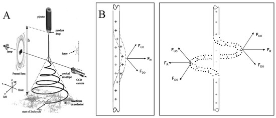
Figure 2.
(A) An electrospinning jet that contained two successive electrical bending instabilities; (B) affected by the repulsion forces between charges, the perturbation segment of the jet (the dashed segment) is affected by the repulsion forces FUO and FDO of the lower and upper charges. The resultant of these forces FR is in the radial direction of the jet, which makes the jet more curved. (A) Reprinted with permission from [17]. Copyright 2000, American Institute of Physics. (B) Reprinted with permission from [16]. Copyright 2008, Elsevier.
There are many factors affecting the preparation of nanofibers by electrospinning, which can be divided into solution properties (such as viscosity, elasticity, electrical conductivity, and surface tension), control variables (such as the static voltage in the capillary, the potential of the capillary port, and the distance between the capillary port and the collector), and environmental parameters (such as solution temperature, air humidity and temperature in the spinning environment, and airflow speed). The main influencing factors include: (1) The concentration of polymer solution: The higher the concentration of polymer solution, the greater the viscosity and the greater the external tension. The droplet cleavage can be weakened by increasing the external tension after leaving the nozzle. Generally, when other conditions remain constant, the fiber diameter increases with the increase in concentration; (2) Electric field strength: With an increase in electric field strength, the jet of the polymer electrospinning solution has a larger outer charge density and thus has a greater electrostatic repulsion. At the same time, the higher electric field strength makes the jet obtain a greater acceleration degree. Both of these factors can cause the jet and fiber to have greater tensile stress, resulting in a higher tensile strain rate, which is conducive to the preparation of finer fibers; (3) The interval between the capillary port and the collector: After the polymer droplets are ejected through the capillary port, they volatilize in the air with the solvent, and the polymer is concentrated and solidified into fibers, which are finally accepted by the receiver. As the distance between the two increases, the diameter decreases; (4) Activity rate of electrospinning fluid: When the diameter of the spinneret is fixed, the average jet velocity is obviously proportional to the diameter of the fiber; (5) The condition of the collector: The condition of the collector is different, and the condition of the produced nanofibers is also different. When the fixed collector is used, the nanofibers appear to have random irregular scenes. When using a rotating disk collector, the nanofibers appear in a parallel pattern. Therefore, the fibromomentum produced by different equipment conditions is different.
In addition to spiraling, the jet will also undergo other shape changes, such as branching and the formation of beads. The undulations increase as the charge density of the jet increases. When the undulations are large enough to become unstable, the jet will branch off. The undulations come from the combined effects of the electric Maxwell stresses and surface tension [31]. Branching occurs more frequently in viscous solutions and at high electric fields. In contrast, when the charge density of the jet is reduced, surface tension will dominate in the competitive relationship between the electric field and surface tension. Capillary instability that results in the transformation of the jet into spherical droplets occurs.
In recent years, researchers have tried to predict the diameter of electrospun nanofibers in various ways, including theoretically or experimentally. Gadkari summarized the literature on various correlations and analyzed them to obtain the relationship dependency of the nanofiber diameter on the viscous and surface charge repulsion effects [33]. A design of the experiments model, analyzing data based on polynomial equations without physical meaning, was proposed by Ruiter to identify the effects of electrospinning parameters on scaffold morphologies of poly-D,L-lactic acid [34]. The model shows that solution concentration plays an important role in the morphology of nanofibers.
3. Regulation of Nanofibers
Diameter, as the most basic parameter of nanofibers, has always been the object of greatest concern to researchers. A variety of investigations have been reported on the effect of electrospinning parameters on the diameter of the nanofibers, both theoretically and experimentally. The diameter of the nanofibers is influenced by the concentration of polymer in solution, the type of solvent, the conductivity, as well as the feeding rate of the solution [35,36]. The higher the concentration and viscosity of the solution, the higher the voltage required to overcome its own surface tension to form the jet; the voltage needs to be optimized to match with the feeding rate of spinning fluid and the collecting distance for producing nanofibers with a uniform diameter.
3.1. Diameter of Nanofibers
It has been reported that the larger the voltage, the smaller the diameter of the nanofibers [37]. However, there was also the observation that the diameter of the nanofibers increased with an increase in the voltage [38]. The reason is that the type of spinning solution and the parameters are not the same. This indicates that the influence of the voltage summarized by simple control variables on the final diameter of the nanofibers is not rigorous enough. Gu et al. reported that the concentration of the spinning fluid has a greater effect on the diameter of the nanofibers than the voltage [39]. In fact, the main factor affecting the diameter of the nanofibers here is the viscosity of the solution, which changes with the concentration of the solution and the molecular weight of the polymer [39,40].
Fridrikh et al. reported that there is a limiting diameter for the jet, which arises from a force balance between surface tension and electrostatic charge repulsion [41]. These two forces are determined by the viscosity and conductivity of the solution, respectively. In the case of ignoring the elastic effect and fluid evaporation, the diameter of the nanofibers can be given by the following equation:
where γ is surface tension of the solution, is the dielectric constant, Q is the flow rate of the solution, I is the current carried by the jet, and χ is proportional to the ratio of the jet diameter h and radius of curvature R. It is shown that the nanofiber diameter decreases with the increase in the charge carried by the jet. However, the electrospinning process is much more complex than this model, so this model is not accurate or comprehensive enough. For example, temperature is an easily overlooked parameter. Most solution electrospinning processes take place at ambient temperature. As the temperature increases, the viscosity and surface tension of solution decrease, leading to a reduction in nanofiber diameter. But at the same time, the increase in temperature will also cause the acceleration of the evaporation of the solvent. In this case, the drawing process, which is also the fining process of the nanofibers, will end prematurely. A temperature equilibrium that minimizes the diameter of the nanofibers can be found [42].
3.2. Morphologies and Structures of Electrospun Nanofibers
Electrospinning has become one of the main ways to prepare nanofibers because of its advantages such as a simple manufacturing device, good adjustable fiber structure, and strong technical combination. It can be used for directly and continuously spinning polyester, polyurethane, polyethylene, and other polymers into ultra-fine and uniform fibers with diameters ranging from less than 3 nm to more than 1 μm and depositing on the receiving plate to obtain non-woven fabric. It is also possible to prepare nanofibers with special shapes by electrospinning in addition to nanofibers with uniform diameters. Porous nanofibers, hollow nanofibers, and bead-on-string nanofibers are produced to meet the requirements of various applications. More complex structures tend to yield better performance, such as a greater specific surface area, rougher surface, or greater surface energy. Next, we will discuss the strategies for producing nanofibers with different morphologies and structures.
3.2.1. Bead-on-String Nanofibers
By adjusting the parameters in the process of electrospinning, electrospun nanofibers with unique morphologies can be simply obtained. Bead-on-string nanofibers are typical. As we discussed earlier, the jets need to overcome capillary instability to form uniform nanofibers. Otherwise, the bead structure will be obtained. At first, the bead structure appears randomly, which is considered an undesirable by-product. It is not until the production of uniform bead-on-string structures that attention is paid to this structure (Figure 3A). Zuo et al. reported how and why this structure was formed [43]. As indicated in Figure 3B, the jet is photographed at different distances from the nozzle. As the jet flows further and further away from the nozzle, the smooth surface of the jet flow first becomes wavy, then dumbbell-like, and finally bead-shaped.
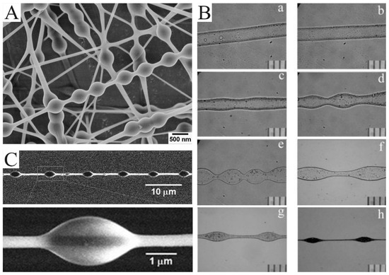
Figure 3.
(A) SEM images of the bead-on-string nanofibers with polyvinyl alcohol (PVA): polystyrene (PS) (1:1) and 9 wt.% PVA for 473 nm PS nanospheres. (B) The bead formation process at different points along the PHBV nanofibers formed by electrospinning. The photos were taken at different distances from the needle tip according to their orders: (a) 1 cm; (b) 3 cm; (c) 5 cm; (d) 7 cm; (e) 9 cm; (f) 12 cm; (g) 15 cm; (h) 30 cm. (C) SEM image of PS nanofibers with a regularly distributed polyethylene glycol (PEG) droplet on it. (A) Reprinted with permission from [44]. Copyright 2012, American Chemical Society. (B) Reprinted with permission from [43]. Copyright 2005, Society of Plastics Engineers. (C) Reprinted with permission from [45]. Copyright 2011, WILEY-VCH.
The bead-on-string structure can be regulated by controlling viscosity, net charge density, and surface tension [46]. Charge repulsion and electric field force are the causes of the drawing and deformation of the jet. Surface tension always makes the liquid the smallest surface area by turning into a sphere, while viscoelastic force resists rapid changes in shape. Therefore, the easiest strategy for producing bead-on-string nanofibers is adjusting the solution concentration and applying voltage. A higher concentration enhances electrostatic repulsion forces and viscoelasticity but reduces surface tension. A polymer solution with a lower concentration tends to produce beads with a higher density [47]. The effect of the viscosity of spinning solution on bead structure can be clearly reflected in an example. By combining electrospinning and electrospraying, Tian et al. obtained PEG beads on PS-string hetero-structured nanofibers in a coaxial jetting process (Figure 3C) [45]. During electrospinning, the outer PEG with a low viscosity is deformed by humidity, while the PS with a high viscosity keeps the shape of a “string”.
The surface tension and viscoelasticity of the jet can be changed by adjusting the proportion of solvent. For example, PS-b-poly(ethylene butylene)-b-PS triblock copolymer solutions, which can be dissolved in different proportions of tetrahydrofuran/N,N-dimethylformamide (THF/DMF), have different rheology data. Accordingly, the viscosity of the solution will vary considerably [48]. In addition, a corona discharge can be used to add neutralizing charge to the jet so as to reduce electrostatic repulsion [46].
3.2.2. Porous Nanofibers
In certain cases, the rapid evaporation of the solvent causes the liquidation of water vapor during the spinning process. Droplets formed by water vapor liquefaction adhere to the jet surface, leading to the formation of pores on the fiber’s surface (Figure 4A) [49]. This approach, which is essentially vapor-induced phase separation, has to meet two requirements: humid environment and volatile solvents, such as THF, methylene chloride, and carbon disulfide. The size and number of pores can be easily controlled by changing the humidity. The higher the humidity, the larger the pore size and the higher the pore density [50]. In addition to controlling environmental humidity, there are other methods of inducing phase separation. McCann et al. electrospun PAN nanofibers into liquid nitrogen [51]. In this process, pores were introduced into the nanofibers surface by thermally induced phase separation. Pores could not only be formed on the surface of the nanofibers but also inside the nanofibers so as to obtain nanofibers with a loose structure. As shown in Figure 4B, Pai et al. used PS/DMF solution to produce fibers with a smooth surface and a porous interior [52]. Compared with a highly volatile solvent mentioned earlier, the evaporation rate of DMF is not fast enough to form small droplets on the jet surface. DMF absorbed water vapor in the air due to a non-solvent phase separation reaction between them. As a result, a porous structure was formed inside the fibers. The growth process of porous structures resulting from phase separation was calculated by Dayal et al. based on the Cahn–Hilliard time-evolution equation and solvent evaporation rate equation [53]. The strategy of introducing pores through phase separation has been applied to a variety of polymers, such as PS [54], poly(L-lactic acid) [55,56], polyvinyl butyral [57], polyethylene terephthalate [58], and poly(ε-caprolactone) [59,60].

Figure 4.
(A) SEM images of electrospun poly(ε-caprolactone) fibers collected in water as a function of pH 3. (B) SEM images of as-spun fibers electrospun from a 30 wt.% PS/DMF solution under 43% relative humidity. The illustration is the cross-sectional TEM images of them. (C) TEM images of the macroporous CNFs obtained by etching SiO2/Sb@CNF composites with an aqueous HF solution. (D) SEM images of the porous CNFs produced from pure PAN, PAN/PS, and PAN/PMMA, respectively. (A) Reprinted with permission from [61]. Copyright 2011, Springer. (B) Reprinted with permission from [52]. Copyright 2009, American Chemical Society. (C) Reprinted with permission from [62]. Copyright 2018, American Chemical Society. (D) Reprinted with permission from [63]. Copyright 2016, Elsevier.
Porous nanofibers can also be produced through the removal of a sacrificial phase. Commonly, the sacrificial phases are salt, polymers, and nanoparticles. A sacrificial phase of salt can be removed by leaching. Gupta et al. used GaCl3 as a template to prepare porous nylon-6 fibers [64]. Wang et al. prepared SiO2/Sb@CNFs by carbonizing electrospun precursors, which were etched with HF solution to remove SiO2 and Sb nanoparticles [62]. What was left were porous CNFs (Figure 4C). The porous CNFs could also be prepared by electrospinning PAN blending with the sacrificial PS or PMMA [63]. PS and PMMA were easier to pyrolyze than PAN. As a result, PS or PAMM was completely pyrolyzed to form pores during carbonization. Moreover, PS foam (Figure 4D) and Nafion are also suitable as a sacrificial phase in PAN solution [65,66].
The introduction of pores has other advantages in addition to greatly increasing the specific surface area of the nanofibers: the functionalization inside the pores is easy to realize for obtaining functional surfaces [67]; and porous CNFs have stronger ionic adsorption and higher specific capacitance [65].
3.2.3. Hollow Nanofibers
Hollow nanofibers are another common structure of electrospun nanofibers. There are two strategies for preparing hollow nanofibers. One is coaxial electrospinning, which we will discuss later. The other strategy is to make the components of the solution spontaneously move along the radial direction of the jet and be stratified by adjusting the ratio of a mixed polymer solution. Niu et al. produced hollow PVA nanofibers by mixing PVAs with different molecular weight [68]. The schematic diagram of the formation of the hollow structure is displayed in Figure 5A. With the same electrospinning parameters, the higher the molecular weight, the higher the distribution in the outer layer. The nanofibers were then carbonized at high temperatures. In this process, the low-molecular weight PVA in the inner layer first pyrolyzed and moved to the high-molecular weight PVA. Hollow CNFs were produced. It is of concern that if inorganic materials were mixed into the solution and the nanofibers carbonized in the protection of argon, the inorganic materials would not move with the low-molecular weight PVA. The inorganic materials aggregated into spheres in the channels of hollow nanofibers, and pea-like nanofibers could be formed. Hollow nanofibers are commonly prepared by similar methods. For example, the fibers have been produced by electrospinning with a mixture of polycarbosilane (PCS) and PS, with PCS in the outer layer and PS in the inner layer. After carbonization, hollow SiC nanofibers were formed, as PCS turned into SiC and PS was pyrolyzed (Figure 5B) [69]. Hollow nanofibers can also be produced based on vapor-induced phase separation. In another example, camphene and tetraethoxysilane, as pore-forming agents, could be added into PS solution. Water entered the surface of the jet in the electrospinning process. At this point, tetraethoxysilane that diffused to the outer layer evaporated, and camphene that diffused to the outer layer was removed after freeze-drying. Hollow and porous structures of electrospun PS fibrers were obtained [70].
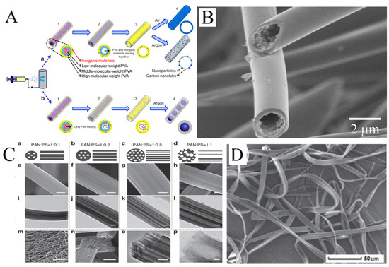
Figure 5.
(A) Schematics of the gradient electrospinning and controlled pyrolysis method. (B) SEM images of hollow silicon carbide nanofibers. (C) (a–d) Schematic diagrams, (e–h,m,n) FESEM and (i–l,o,p) TEM images of LRC nanofibers based on various PAN/PS weight ratio: (a,e,i) 1:0.1, (b,f,j) 1:0.2, (c,g,k,m–p) 1:0.5, (d,h,l) 1:1. Scale bars, 200 nm (e–l,o), 20 μm (m), 500 nm (n), 20 nm (p). (D) SEM images of microfibers electrospun from PMAGH-block-PS-block-PMAGH in 0.20 g mL−1 CHCl3 solution at 20 µL min−1 feeding rate. (A) Reprinted with permission from [68]. Copyright 2015, Macmillan. (B) Reprinted with permission from [69]. Copyright 2018, Elsevier. (C) Reprinted with permission from [71]. Copyright 2015, WILEY-VCH. (D) Reprinted with permission from [72]. Copyright 2019, WILEY-VCH.
Some hollow fibers with more interesting structures have been reported by electrospinning. For example, hollow fibers with multiple channels produced with a mixture of PAN and PS have been reported. PS as the sacrificial phase will form more than one channel inside PAN. The number and distribution of channels will vary with the ratio of PAN to PS in the solution (Figure 5C) [71]. In addition, it is possible to obtain ribbon fibers in the production of hollow fibers, and unique polymer skin can form on the surface of the jet. After that, the evaporation of solvent will result in the vacuum inside, leading to the collapse of skin (Figure 5D) [72,73,74].
4. Application of Electrospun Nanofibers in Electrochemical Biosensors
Electrochemical biosensors have attracted more and more attention due to their speed, simple operation, and low cost. Electrospun nanofibers have been extensively applied in electrochemical biosensors for the determination of various molecules such as glucose, hydrogen peroxide (H2O2), uric acid (UA), dopamine (DA), ascorbic acid (AA), protein, and amino acids.
4.1. Glucose Sensors
As a source of energy in the body, glucose is widely found in every corner of our life. People who want to lose weight need to know the amount of glucose in their diet in order to control their diet properly. Diabetics need to regularly measure their blood sugar levels to keep themselves healthy.
Glucose oxidase (GOx) is one of the main choices for real-time glucose monitoring owing to its high glucose selectivity. Nanofibers, due to their high specific surface area and porous structure, are excellent platforms for enzyme immobilization. The activity of the immobilized enzyme greatly affects the performance of the sensor. As implied in Figure 6A, the activity of GOx immobilized on the surface of PVA/malonic acid nanofibers with different plasma processing was quite different [75]. In addition, the reusability and storage stability of the plasma-treated fibers was significantly improved (Figure 6B,C). When designing the glucose sensor based on GOx, the nanofibers as the substrate have great influence on the performance of the sensor. Guo et al. produced CNFs with uniformly embedded TiC nanoparticles (Figure 6D,E) [76]. The robust adhesion of the composite nanofibers provides more abundant active sites for enzyme immobilization (Figure 6F). The GOx-TiC-CNFs biosensor could selectively detect glucose with a wide linear range (0.013–10.5 mM) and low detection limit (3.7 μM).
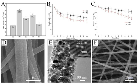
Figure 6.
(A) Activity of GOx immobilized on the surfaces of (a) untreated and (b) air-, (c) nitrogen-, (d) CO2-, and (e) argon plasma-treated PVA/malonic acid nanofibers. (B) Reusability of GOx immobilized on (a) unmodified and (b) air plasma-modified nanofibers. (C) Storage stability of GOx immobilized on (a) unmodified and (b) air plasma-modified nanofibers. (D) SEM images of TiC CNFs. (E) TEM images of TiC CNFs; inset of (E) is the HRTEM image. (F) SEM image of GOx–TiC CNFs. (A–C) Reprinted with permission from [75]. Copyright 2016, Elsevier. (D–F) Reprinted with permission from [76]. Copyright 2018, Elsevier.
Enzymes are unstable at certain temperatures and pH values. Therefore, non-enzyme sensors have been developed in which enzymes are generally replaced by metals or metal oxides. Non-enzyme sensors are more economical than enzymatic sensors and are less affected by the environment. Glucose is the most popular analyte. A variety of transition metals are used in non-enzyme electrochemical sensors for glucose. The mechanism diagram of the transition metal electrocatalytic detection of glucose is illustrated in Figure 7A. For example, Lu et al. reported a glassy carbon electrode (GCE) modified with CuO/Cu2O composite nanofibers for a glucose sensor [77]. CuO/Cu2O composite nanofibers had good electrocatalytic activity for glucose. The possible electrocatalytic processes of glucose can be explained as follows: The electrons produced by the oxidation of Cu2+ to Cu3+ form an oxidation peak in the cyclic voltammograms. After that, Cu oxidizes glucose to gluconolactone, which further increases the oxidation current [78,79,80]. In a specific range of glucose concentration, the oxidation peak increases linearly with the increase in glucose concentration. This property enables the determination of glucose concentration by the magnitude of the oxidation current (Figure 7B) [81]. Increased conductivity can accelerate electron transfer and improve the performance of the sensors. CNFs have excellent mechanical and electrical properties and can be simply obtained using carbonized electrospun polymer nanofibers, making them suitable as carriers for metal oxide nanoparticles. In addition, the synergistic effect of multiple components can also greatly enhance the electrocatalytic performance. The reason may be that the defects caused by the lattice mismatch of the two metal atoms lead to electron accumulation at the interface and the upward shift of the D band. Shi et al. prepared electrospun CuO nanofibers, CuO/CNFs, and CuO/NiO nanofibers as a glucose sensor, as shown in Figure 7C [82]. The electrocatalytic effect can be observed through the magnitude of the catalytic current and the position of the oxidation peak potential. Obviously, CuO/NiO nanofibers can produce higher current at lower potential.
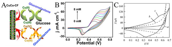
Figure 7.
(A) Schematic diagram of the transition metal electrocatalysis detection of glucose. (B) CVs for Ni2P nanofibers in 0.1 M NaOH (pH 13) with the presence of varying glucose concentrations ranging from 0 to 8 mM. (C) CVs of (a) CuO-NFs, (b) CuO/CNFs, and (c) CuO/NiO-NFs film electrodes in 0.1 mol L−1 NaOH containing 0.6 mmol L−1 glucose at 50 mV s−1. (A) Reprinted with permission from [80]. Copyright 2016, American Chemical Society. (B) Reprinted with permission from [81]. Copyright 2016, American Chemical Society. (C) Reprinted with permission from [82]. Copyright 2013, WILEY-VCH.
There have been many reports on the application of electrospinning to non-enzyme electrocatalysts for the detection of glucose. Saravanan et al. prepared Co-Fe/PVdF-HFP by electrospinning and chemical reduction techniques for electrochemical glucose detection, in which the diffusion and adsorption of glucose in the expanded cavities and pores of the polymer nanofibers were accelerated to maximize the utilization efficiency of glucose [83]. Luo et al. fabricated a Pt-Au/polyurethane sensing patch through electrospinning, magnetron sputtering, and electrodeposition techniques for the determination of glucose in a neutral condition (pH 7.4) [84]. Li et al. synthesized hollow CuO/NiO nanoparticles with adjustable sizes by coaxial electrospinning and subsequent calcination [85]. The unique morphology and high specific surface area as well as the hetero-structural interface between CuO and NiO are conducive to improving the electrocatalytic performance, showing excellent electrocatalytic performance for glucose oxidation. They also prepared nano-Mn3O4/NiO-decorated CNFs by electrospinning and calcination [86]. The conductive network constructed by CNFs not only promotes the transfer of electrons but also provides a landing site for nanoparticles, thereby reducing the aggregation of nanoparticles and exposing more active sites. Kim et al. embedded MnO nanostructures with CNFs to significantly improve the detection performance of non-enzymatic amperometric glucose sensors [87]. Additionally, other nanofibers are also used in glucose biosensors, such as Ni2P/CNFs [88], PAN/PANI/CuO [89], CuSn/CNFs [90], and CuCo-P350 [91]. Table 1 summarizes several examples of non-enzyme electrochemical glucose sensors, including the detection limit, sensitivity, linear range, and oxidation potential.

Table 1.
Electrospun nanofibers for non-enzyme glucose electrochemical biosensors.
4.2. H2O2 Sensors
In organisms, H2O2 is a signaling molecule that controls cell metabolism. In addition, it is also associated with some human diseases, such as cardiovascular diseases, Alzheimer’s Disease, and cancers [92]. Therefore, the detection of H2O2 is of great significance in medical applications.
Noble metal (such as Au [93], Ag [94], Pd [95], and Pt [96]) nanoparticles have excellent electrocatalytic activity with H2O2. For example, Huang et al. electrospun Pd nanoparticle-loaded CNFs to modify a carbon paste electrode (CPE) [97]. The modified CPE shows a wide linear range (0.2 μM to 20 mM) for H2O2 (Figure 8A). As shown in Figure 8B, Zhang et al. compared the cyclic voltammetry of H2O2 on PVDF, a multi-walled carbon nanotube (MWCNT), and Pt [98]. It was not difficult to see that the electrocatalytic performance of H2O2 mainly came from Pt. Without Pt, PVDF or MWCNT alone showed almost no current response to H2O2.
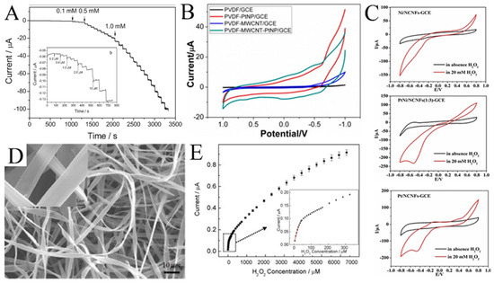
Figure 8.
(A) Current–time responses of the Pd/CNFs-CPE upon successive injection of a specific concentration of H2O2 into N2-saturated PBS (0.1 M, pH 7.0); the inset (b) shows the performance of the Pd/CNFs-CPE in the amperometric detection of a low concentration of H2O2. Applied potential: −0.2 V. (B) CVs of GCEs modified with PVDF, PVDF-PtNP, PVDF-MWCNT, and PVDF-MWCNT-Pt hybrid nanofiber membranes. (C) CVs of Ni/CNFs-GCE, PtNi/CNFs-GCE, and Pt/CNFs-GCE in the absence and presence of H2O2 at 50 mV s−1. (D) Typical SEM images of Hb microbelts. (E) The corresponding calibration plot of amperometric response towards H2O2. Inset: enlarged drawing of the calibration plot for low H2O2 concentrations. (A) Reprinted with permission from [97]. Copyright 2008, WILEY-VCH. (B) Reprinted with permission from [98]. Copyright 2014, American Chemical Society. (C) Reprinted with permission from [99]. Copyright 2018, Elsevier. (D,E) Reprinted with permission from [100]. Copyright 2010, Elsevier.
High cost limits the development of H2O2 sensors based on noble metals, so various transition metals/metal oxides are introduced to functionalize noble metals. As shown in Figure 8C, compared with Pt/CNFs and Ni/CNFs, the electrocatalytic performance of PtNi/CNFs for H2O2 is much better [99]. The PtNi/CNFs-modified GCE has a wide detection range from 0.05 μM to 8 mM with a low detection limit of 0.0375 μM for H2O2. Mohammadi et al. synthesized a Se/P@N-doped carbon nanobox (N-CNB)/CNFs for the electrochemical determination of H2O2 [21]. Due to the mesoporous structure, the open efficient diffusion channel for H2O2, the rapid mass/electron transfer, and the synergies between P, Se, and CNBs/CNFs, the synthesized Se/P@(N-CNB)/CNFs exhibited excellent electrocatalytic activity toward H2O2 oxidation. Hsueh et al. prepared IrO2@Ir NFs for the selective determination of H2O2 [86]. Qu et al. synthesized LaSrNiO NFs with a dual-phase structure and unique porous tubular nanofiber structure using electrospinning and high-temperature calcination techniques, significantly improving their redox performance for the electrochemical sensing of H2O2 [101]. Bi et al. modified the conductive polymer PEDOT:PSSLiTFSI-CoPc (PPLC) on nanofibers (PPLC/PU/PDMS) to develop a stretchable electrochemical sensor [102]. The electrode displayed good electrochemical sensing performance and stability under mechanical deformation. In addition, Ag@CuO [103], VCoO/C-750 [104], and Co-NC/CNF [105] are also used for H2O2 detection. Table 2 lists several examples of H2O2 sensors using electrospun metals/metal oxides nanofibers.
Table 2.
Electrospun nanofibers for H2O2 analysis.
Interestingly, hemoglobin microbelts have been successfully electrospun for H2O2 sensing by Ding et al. (Figure 8D) [100]. In their work, hemoglobin is dissolved in 2,2,2-trifluoroethanol as the spinning solution for electrospinning hemoglobin microbelts, allowing for the sensitive detection of H2O2 at physiological pH (0.1 M pH 7.0 phosphate buffer). As shown in Figure 8E, this H2O2 sensor has a low detection limit (0.61 μM) and high stability due to its good biocompatibility and direct electron transfer capability.
4.3. Detection of Other Biomolecules
A variety of electrospun nanofibers have been developed for the detection of biomolecules, such as UA, DA, AA, protein, and amino acids. The level of these biomolecules in the body can reflect the health of the body and help doctors determine whether the body is suffering from certain diseases. For example, the concentration level of UA is one essential indicator for the diagnosis and the prognosis of some multifunctional disorders like gout, hypertension, and cardiovascular diseases [106]. DA is an important neurotransmitter, having strong influence on the central nervous, renal, cardiovascular, and hormonal systems [107].
CNFs have been widely used in electroanalysis due to their good dispersibility, wettability, conductivity, and biocompatibility. In some cases, the electrochemical performance of CNFs may be even better than that of CNTs (Figure 9A) [107,108]. CNFs can be easily obtained by carbonizing electrospun polymer nanofibers at high temperature. Tang et al. prepared electrospun CNFs-modified CPE to detect trace amounts of L-tryptophan (Trp), L-tyrosine (Tyr), and L-cysteine (Cys) [109]. The modified electrode showed a satisfactory linear range (0.1–118.5 μM for Trp, 0.2–109 μM for Tyr, and 0.15–63.8 μM for Cys). As implied in Figure 9B, in addition to the obvious current response to Trp, Tyr, and Cys, the CNFs-modified electrode also showed a response to UA and AA. The results show that CNFs can detect multiple biomolecules simultaneously by DPV. Recently, effort has been devoted to improving the electrocatalytic performance of CNFs, including the combination with MWCNTs and precious metals (such as Pd and Ag) [106,110,111].

Figure 9.
(A) DPVs at (a) CPE, (b) MWCNT-CPE, and (c) CNFs-CPE in 0.1 M PBS (pH 4.5) containing 2 μM DA, 6 μM AA, and 2 μM UA. DPV conditions: scan rate, 20 mV s−1; amplitude, 50 mV; pulse width, 100 ms; pulse period, 200 ms. (B) DPVs of CNFs-CPE in 0.1 M PBS (pH 7.0) containing 0.1 mM UA, 0.2 mM AA, and 0.2 mM Trp (a), 1 mM Cys (b), and 0.2 mM Tyr (c). DPV conditions: Scan rate, 6 mVs−1; amplitude, 50 mV; pulse width, 100 ms; pulse period, 200 ms. (C) Schematic diagram representing the developed electrochemical sensor and fluorescent sensor based on a PANi/CQDs composite. (A) Reprinted with permission from [108]. Copyright 2008, Elsevier. (B) Reprinted with permission from [109]. Copyright 2009, Elsevier. (C) Reprinted with permission from [112]. Copyright 2020, The Polymer Society.
An interesting example is the dopamine biosensor based on the electrospun PANi/carbon quantum dots (CQDs) composite nanofibers [112]. On one hand, CQDs have electrocatalytic activity with dopamine. On the other hand, the addition of dopamine can cause the fluorescence quenching of CQDs. Therefore, the electrospun PANi/CQDs composite nanofibers are capable of both electrochemical and fluorescent sensors for DA (Figure 9C). In another work, Samie et al. combined a novel RuO2-CeO2-AuNFs hybrid structure with graphite oxide and functionalized multiwalled carbon nanotubes for the simultaneous determination of serotonin, DA, and AA [113]. The proposed electrochemical sensor reduces overpotential and solves the problem of overlapping the oxidation peak potential. Yin et al. decorated nitrogen-doped electrospun CNFs with tightly packed Co3O4 nanoparticles with a high electroactive surface area and promoted electron transfer between the electrode surface and the target molecule by rapid electrodeposition [114]. The electrosensing platform showed excellent sensitivity and selectivity for DA. Veeralingam et al. demonstrated a high-performance field-effect transistor biosensor based on Al-functionalized β-Bi2O3 nanofibers for the highly selective and rapid detection of serotonin [115]. The biotransistor has good sensitivity, stability, and repeatability and a fast response time of 0.8 s.
Enzymes and antibodies could be immobilized on electrospun nanofibers for the specific identification and detection of biomolecules. For example, Mondal et al. covalently immobilized cholesterol esterase and cholesterol oxidase on electrospun TiO2 nanofibers with a high orientation for the detection of esterified cholesterol [116]. Atilgan et al. prepared dendrimer-modified montmorillonite-decorated poly-σ-caprolactone and chitosan-based nanofibers, which were conjugated with glutamate oxidase for the electrochemical determination of monosodium glutamate [117]. Proteins can be detected by immobilizing antibodies on electrospun nanofibers through the specific binding between antigens and antibodies. For example, Macwan et al. immobilized anti-C-reactive protein on electrospun PVA/CNT nanofibers for the detection of inflammatory marker C-reactive protein [118].
5. Challenges and Opportunities Facing Practical Application
Although electrospinning technology has been deeply developed and its application has been extensively explored in many fields, there are still many issues left in both basic theory and practical application:
- (i)
- Improvement of the theoretical model about jet: Although many models of jet movement in the electrostatic field have been established, these models are incomplete and are mostly half-empirical and half-theoretical [39,119,120]. In short, the theoretical model is still in its infancy.
- (ii)
- Precise control of environmental factors: It has been widely reported that temperature and humidity have great influence on the morphology of electrospun nanofibers [42,121]. In the laboratory, the environmental factors of electrospinning are relatively easy to maintain. However, in order to realize the commercialization of electrospun nanofibers, large-scale production is inevitable. Under such circumstances, it is still a challenge to keep the environment stable.
- (iii)
- Safety issues caused by solvent volatilization: A large amount of solvent volatilizes during the solidification of the jet. In large-scale production, the amount of solvent volatilization will become larger. Solvents widely used in electrospinning include DMF, DMSO, and sometimes acetone, which are toxic and may cause explosions.
- (iv)
- Safety of nanofibers: Some research has suggested that nanofibers are likely to cause an inhalation hazard. For example, inhalation of a sufficient dose of asbestos nanofibers may cause mesothelioma [122]. At present, there are few studies on the inhalation safety of nanofibers. An in-depth study of this aspect is of great significance. Although electrospinning technology can protect our health, it can be more harmful if we ignore its own safety.
- (v)
- Miniaturization of biosensors: With the advent of the 5G era, online medical treatment is available. People can enjoy medical services at home without the tedious procedures of offline medical treatment. Traditional testing methods usually require expensive testing equipment and complicated operations. Microscale biosensors would make online diagnosis easier. Several test papers and miniaturized instruments have been reported, but these fall far short of the need for online diagnoses [123,124]. The design of miniaturized biosensors may be a hotspot in the future.
- (vi)
- The bionic device: Electrospun nanofiber mats mostly have excellent flexibility, which makes electrospinning technology promising in biomimetics. For example, PVDF, a piezoelectric material usually used for electrospinning, has been reported for the design of electronic skin (Figure 10A) [125,126,127]. There have also been a number of reports about electronic tongues, although they were only in the initial stage (Figure 10B) [128,129,130]. With the development of technology, it will be possible to integrate electronic tongues into real tongue sizes in the future. In addition, we can imagine that the PVDF nanofibers with piezoelectric properties could be used as not only electronic skin, but also electronic ears, an electronic throat, and even an electronic heart. On the software side, AI is developing rapidly. In this sense, bionic humans, the stuff of science fiction, may become a reality in the distant or even near future.
 Figure 10. (A) Photograph of the e-skin based on a piezoelectric nanogenerator by electrospun PVDF nanofibers. The inset shows the demonstration of its analog to a neuron cell. (B) Schematic illustration of the multi-ion-selective electrode. (A) Reprinted with permission from [120]. Copyright 2018, American Chemical Society. (B) Reprinted with permission from [124]. Copyright 2020, Elsevier.
6. Conclusions
Electrospinning is a simple and efficient method for producing nanofibers. Electrospun nanofibers have large specific surface area, high porosity, and diversified structure. In addition, it is easy to functionalize the surface of electrospun nanofibers. These advantages make electrospinning technology have great potential in electrochemical sensors. In the past decades, a large number of studies have laid the foundation for the control of the structure and morphology of electrospun nanofibers, and many interesting composite nanofibers structures have been witnessed in practical applications of electrochemical sensing.
In this review, an overview was provided on the morphological and structural regulation of nanofibers by electrospinning technology as well as its application in electrochemical sensors. The factors affecting the morphology of the nanofibers and the strategies for producing nanofibers with special morphology were discussed. Generally, the performance of nanofibers can be improved and their application can be expanded through the following strategies: (i) nanofiber diameter; (ii) special morphology (hollow, core-sheath, porous and bead-like); (iii) functionalization of surfaces; (iv) metallization of nanofibers; and (v) carbonization to form CNFs. The working principles and advantages of various nanofibers obtained by these strategies in the detection of different substances were also discussed in this review.
In summary, many achievements have been made in both the theory and application of electrospinning technology in recent decades. Electrospinning has been involved in many fields, such as energy storage, tissue engineering, environmental protection, smart textiles, electronic devices, and physical and chemical sensors. In particular, the current research on electrospinning has a tendency of miniaturization, simplification, and economization, making it possible for the technique to play an important role in intelligent medical treatment. However, there are still many issues. For example, process and safety problems still exist in the large-scale production of electrospinning. In addition, it is necessary to establish a complete evaluation system for the safety of electrospun nanofibers.
Author Contributions
Conceptualization, J.L., K.H. and L.L.; investigation, J.L., Z.D., K.H., Z.H. and D.D; writing—original draft preparation, J.L., Z.D., K.H., Z.H. and D.D.; writing—review and editing, J.L., Z.D., D.D. and L.L.; supervision, Q.Z. and L.L.; project administration, L.L. All authors have read and agreed to the published version of the manuscript.
Funding
This research was funded by the National Natural Science Foundation of China (grant numbers 61971274 and 62171268).
Institutional Review Board Statement
Not applicable.
Informed Consent Statement
Not applicable.
Data Availability Statement
Not applicable.
Conflicts of Interest
The authors declare no conflicts of interest.
References
- Luo, C.J.; Stoyanov, S.D.; Stride, E.; Pelan, E.; Edirisinghe, M. Electrospinning versus fibre production methods: From specifics to technological convergence. Chem. Soc. Rev. 2012, 41, 4708–4735. [Google Scholar] [CrossRef] [PubMed]
- Lu, N.; Jing, X.D.; Xu, Y.; Lu, W.; Liu, K.C.; Zhang, Z.Y. Effective cascade modulation of charge-carrier kinetics in the well- designed multi-component nanofiber system for highly-efficient photocatalytic hydrogen generation. Acta Phys. Chim. Sin. 2023, 39, 2207045. [Google Scholar] [CrossRef]
- Wang, C.H.; Shao, C.L.; Zhang, X.T.; Liu, Y. SnO2 Nanostructures-TiO2 nanofibers heterostructures: Controlled fabrication and high photocatalytic properties. Inorg. Chem. 2009, 48, 7261–7268. [Google Scholar] [CrossRef] [PubMed]
- Zhang, B.; Kang, F.; Tarascon, J.M.; Kim, J.K. Recent advances in electrospun carbon nanofibers and their application in electrochemical energy storage. Prog. Mater. Sci. 2016, 76, 319–380. [Google Scholar] [CrossRef]
- Jian, S.; Zhu, J.; Jiang, S.; Chen, S.; Fang, H.; Song, Y.; Duan, G.G.; Zhang, Y.F.; Hou, H.Q. Nanofibers with diameter below one nanometer from electrospinning. RSC Adv. 2018, 8, 4794–4802. [Google Scholar] [CrossRef]
- Ahlawat, J.; Kumar, V.; Gopinath, P. Carica papaya loaded poly(vinyl alcohol)-gelatin nanofibrous scaffold for potential application in wound dressing. Mater. Sci. Eng. C Mater. Biol. Appl. 2019, 103, 109834. [Google Scholar] [CrossRef]
- Shojaie, S.; Rostamian, M.; Samadi, A.; Alvani, M.A.S.; Khonakdar, H.A.; Goodarzi, V.; Zarrintaj, R.; Servatan, M.; Asefnejad, A.; Baheiraei, N.; et al. Electrospun electroactive nanofibers of gelatin-oligoaniline/poly(vinyl alcohol) templates for architecting of cardiac tissue with on-demand drug release. Polym. Adv. Technol. 2019, 30, 1473–1483. [Google Scholar] [CrossRef]
- Patel, S.; Hota, G. Synthesis of novel surface functionalized electrospun PAN nanofibers matrix for efficient adsorption of anionic CR dye from water. J. Environ. Chem. Eng. 2018, 6, 5301–5310. [Google Scholar] [CrossRef]
- Thenmozhi, S.; Krishnaveni, T.; Kadirvelu, K. Reduction of nitrocompounds in aqueous medium using electrospun MgO nanofibers. Mater. Res. Express 2019, 6, 065020. [Google Scholar] [CrossRef]
- Ruiz, V.; Perez-Marquez, A.; Maudes, J.; Grande, H.J.; Murillo, N. Enhanced photostability and sensing performance of graphene quantum dots encapsulated in electrospun polyacrylonitrile nanofibrous filtering membranes. Sens. Actuators B Chem. 2018, 262, 902–912. [Google Scholar] [CrossRef]
- Robbins, R.J. Phenolic acids in foods: An overview of analytical methodology. J. Agric. Food Chem. 2003, 51, 2866–2887. [Google Scholar] [CrossRef] [PubMed]
- Safdarian, M.; Hashemi, P.; Ghiasvand, A. A fast and simple method for determination of beta-carotene in commercial fruit juice by cloud point extraction-cold column trapping combined with UV-Vis spectrophotometry. Food Chem. 2021, 343, 128481. [Google Scholar] [CrossRef] [PubMed]
- Smith, C.A.; Want, E.J.; O’Maille, G.; Abagyan, R.; Siuzdak, G. XCMS: Processing mass spectrometry data for metabolite profiling using nonlinear peak alignment, matching, and identification. Anal. Chem. 2006, 78, 779–787. [Google Scholar] [CrossRef] [PubMed]
- Grieshaber, D.; MacKenzie, R.; Voros, J.; Reimhult, E. Electrochemical biosensors: Sensor principles and architectures. Sensors 2008, 8, 1400–1458. [Google Scholar] [CrossRef] [PubMed]
- Kalambate, P.K.; Rao, Z.; Dhanjai; Wu, J.; Shen, Y.; Boddula, R.; Huang, Y.H. Electrochemical (bio) sensors go green. Biosens. Bioelectron. 2020, 163, 112270. [Google Scholar] [CrossRef]
- Reneker, D.H.; Yarin, A.L. Electrospinning jets and polymer nanofibers. Polymer 2008, 49, 2387–2425. [Google Scholar] [CrossRef]
- Reneker, D.H.; Yarin, A.L.; Fong, H.; Koombhongse, S. Bending instability of electrically charged liquid jets of polymer solutions in electrospinning. J. Appl. Phys. 2000, 87, 4531–4547. [Google Scholar] [CrossRef]
- Pan, C.T.; Chang, C.C.; Yang, Y.S.; Yen, C.K.; Kao, Y.H.; Shiue, Y.L. Development of MMG sensors using PVDF piezoelectric electrospinning for lower limb rehabilitation exoskeleton. Sens. Actuators A Phys. 2020, 301, 111708. [Google Scholar] [CrossRef]
- Liu, Z.H.; Pan, C.T.; Lin, L.W.; Lai, H.W. Piezoelectric properties of PVDF/MWCNT nanofiber using near-field electrospinning. Sens. Actuators A Phys. 2013, 193, 13–24. [Google Scholar] [CrossRef]
- Chauhan, D.; Gupta, P.K.; Solanki, P.R. Electrochemical immunosensor based on magnetite nanoparticles incorporated electrospun polyacrylonitrile nanofibers for vitamin-D3 detection. Mater. Sci. Eng. C Mater. Biol. Appl. 2018, 93, 145–156. [Google Scholar] [CrossRef]
- Mohammadi, F.; Roushani, M.; Hosseini, H. Selenium and phosphide-doped hollow porous N-doped carbon nanobox-based electrospun N-doped carbon nanofibers toward electrochemical sensing of hydrogen peroxide. New J. Chem. 2024, 48, 8074–8081. [Google Scholar] [CrossRef]
- Al-Enizi, A.M.; Elzatahry, A.A.; Abdullah, A.M.; Vinu, A.; Iwai, H.; Al-Deyab, S.S. High electrocatalytic performance of nitrogen-doped carbon nanofiber-supported nickel oxide nanocomposite for methanol oxidation in alkaline medium. Appl. Surf. Sci. 2017, 401, 306–313. [Google Scholar] [CrossRef]
- Zhang, H.; Zhang, G.H.; Li, Z.Q.; Qu, K.; Shi, H.M.; Zhang, Q.F.; Duan, H.G.; Jiang, J.H. Osiers-sprout-like heteroatom-doped carbon nanofibers as ultrastable anodes for lithium/sodium ion storage. Nano Res. 2018, 11, 3791–3801. [Google Scholar] [CrossRef]
- McKee, M.G.; Layman, J.M.; Cashion, M.P.; Long, T.E. Phospholipid nonwoven electrospun membranes. Science 2006, 311, 353–355. [Google Scholar] [CrossRef] [PubMed]
- Taylor, G. Disintegration of water drops in an electric field. Proc. R. Soc. Lond. Ser. A Math. Phys. Sci. 1964, 280, 383–397. [Google Scholar] [CrossRef]
- Taylor, G. The force exerted by an electric field on a long cylindrical conductor. Proc. R. Soc. Lond. Ser. A Math. Phys. Sci. 1966, 291, 145–158. [Google Scholar] [CrossRef]
- Taylor, G.I.; Van Dyke, M.D. Electrically driven jets. Proc. R. Soc. Lond. A Math. Phys. Sci. 1969, 313, 453–475. [Google Scholar] [CrossRef]
- Yarin, A.L.; Koombhongse, S.; Reneker, D.H. Bending instability in electrospinning of nanofibers. J. Appl. Phys. 2001, 89, 3018–3026. [Google Scholar] [CrossRef]
- Hohman, M.M.; Shin, M.; Rutledge, G.; Brenner, M.P. Electrospinning and electrically forced jets. II. Applications. Phys. Fluids 2001, 13, 2221–2236. [Google Scholar] [CrossRef]
- Yarin, A.L.; Koombhongse, S.; Reneker, D.H. Taylor cone and jetting from liquid droplets in electrospinning of nanofibers. J. Appl. Phys. 2001, 90, 4836–4846. [Google Scholar] [CrossRef]
- Yarin, A.L.; Kataphinan, W.; Reneker, D.H. Branching in electrospinning of nanofibers. J. Appl. Phys. 2005, 98, 064501. [Google Scholar] [CrossRef]
- He, J.H.; Wan, Y.Q.; Yu, J.Y. Allometric scaling and instability in electrospinning. Int. J. Nonlinear Sci. Numer. Simul. 2004, 5, 243–252. [Google Scholar] [CrossRef]
- Gadkari, S.B. Scaling analysis for electrospinning. SpringerPlus 2014, 3, 705. [Google Scholar] [CrossRef]
- Ruiter, F.A.A.; Alexander, C.; Rose, F.; Segal, J.I. A design of experiments approach to identify the influencing parameters that determine poly-D,L-lactic acid (PDLLA) electrospun scaffold morphologies. Biomed. Mater. 2017, 12, 055009. [Google Scholar] [CrossRef]
- Mahmoudifard, M.; Vossoughi, M. Different PES nanofibrous membrane parameters effect on the efficacy of immunoassay performance. Polym. Adv. Technol. 2019, 30, 1968–1977. [Google Scholar] [CrossRef]
- Baji, A.; Mai, Y.W.; Wong, S.C.; Abtahi, M.; Chen, P. Electrospinning of polymer nanofibers: Effects on oriented morphology, structures and tensile properties. Compos. Sci. Technol. 2010, 70, 703–718. [Google Scholar] [CrossRef]
- Hu, J.; Wang, X.; Ding, B.; Lin, J.; Yu, J.; Sun, G. One-step electro-spinning/netting technique for controllably preparing polyurethane nano-fiber/net. Macromol. Rapid Commun. 2011, 32, 1729–1734. [Google Scholar] [CrossRef]
- Demira, M.M.; Yilgorb, I.; Yilgorb, E.; Erman, B. Electrospinning of polyurethane fibers. Polymer 2002, 43, 3303–3309. [Google Scholar] [CrossRef]
- Gu, S.Y.; Ren, J.; Vancso, G.J. Process optimization and empirical modeling for electrospun polyacrylonitrile (PAN) nanofiber precursor of carbon nanofibers. Eur. Polym. J. 2005, 41, 2559–2568. [Google Scholar] [CrossRef]
- Gupta, P.; Elkins, C.; Long, T.E.; Wilkes, G.L. Electrospinning of linear homopolymers of poly(methyl methacrylate): Exploring relationships between fiber formation, viscosity, molecular weight and concentration in a good solvent. Polymer 2005, 46, 4799–4810. [Google Scholar] [CrossRef]
- Fridrikh, S.V.; Yu, J.H.; Brenner, M.P.; Rutledge, G.C. Controlling the fiber diameter during electrospinning. Phys. Rev. Lett. 2003, 90, 144502. [Google Scholar] [CrossRef]
- Yang, G.Z.; Li, H.P.; Yang, J.H.; Wan, J.; Yu, D.G. Influence of working temperature on the formation of electrospun polymer nanofibers. Nanoscale Res. Lett. 2017, 12, 55. [Google Scholar] [CrossRef]
- Zuo, W.; Zhu, M.; Yang, W.; Yu, H.; Chen, Y.; Zhang, Y. Experimental study on relationship between jet instability and formation of beaded fibers during electrospinning. Polym. Eng. Sci. 2005, 45, 704–709. [Google Scholar] [CrossRef]
- Yuan, W.; Zhang, K.Q. Structural evolution of electrospun composite fibers from the blend of polyvinyl alcohol and polymer nanoparticles. Langmuir 2012, 28, 15418–15424. [Google Scholar] [CrossRef]
- Tian, X.; Bai, H.; Zheng, Y.; Jiang, L. Bio-inspired heterostructured bead-on-string fibers that respond to environmental wetting. Adv. Funct. Mater. 2011, 21, 1398–1402. [Google Scholar] [CrossRef]
- Fong, H.; Chun, I.; Reneker, D.H. Beaded nanofibers formed during electrospinning. Polymer 1999, 40, 4585–4592. [Google Scholar] [CrossRef]
- Kadam, V.; Kyratzis, I.L.; Truong, Y.B.; Schutz, J.; Wang, L.; Padhye, R. Electrospun bilayer nanomembrane with hierarchical placement of bead-on-string and fibers for low resistance respiratory air filtration. Sep. Purif. Technol. 2019, 224, 247–254. [Google Scholar] [CrossRef]
- Wang, L.; Topham, P.D.; Mykhaylyk, O.O.; Yu, H.; Ryan, A.J.; Fairclough, J.P.; Bras, W. Self-assembly-driven electrospinning: The transition from fibers to intact beaded morphologies. Macromol. Rapid Commun. 2015, 36, 1437–1443. [Google Scholar] [CrossRef]
- Megelski, S.; Stephens, J.S.; Chase, D.B.; Rabolt, J.F. Micro- and nanostructured surface morphology on electrospun polymer fibers. Macromolecules 2002, 35, 8456–8466. [Google Scholar] [CrossRef]
- Casper, C.L.; Stephens, J.S.; Tassi, N.G.; Chase, D.B.; Rabolt, J.F. Controlling surface morphology of electrospun polystyrene fibers: Effect of humidity and molecular weight in the electrospinning process. Macromolecules 2004, 37, 573–578. [Google Scholar] [CrossRef]
- McCann, J.T.; Marquez, M.; Xia, Y. Highly porous fibers by electrospinning into a cryogenic liquid. J. Am. Chem. Soc. 2006, 128, 1436–1437. [Google Scholar] [CrossRef]
- Pai, C.L.; Boyce, M.C.; Rutledge, G.C. Morphology of porous and wrinkled fibers of polystyrene electrospun from dimethylformamide. Macromolecules 2009, 42, 2102–2114. [Google Scholar] [CrossRef]
- Dayal, P.; Liu, J.; Kumar, S.; Kyu, T. Experimental and theoretical investigations of porous structure formation in electrospun fibers. Macromolecules 2007, 40, 7689–7694. [Google Scholar] [CrossRef]
- Chen, P.Y.; Tung, S.H. One-step electrospinning to produce nonsolvent-induced macroporous fibers with ultrahigh oil adsorption capability. Macromolecules 2017, 50, 2528–2534. [Google Scholar] [CrossRef]
- Qi, Z.; Yu, H.; Chen, Y.; Zhu, M. Highly porous fibers prepared by electrospinning a ternary system of nonsolvent/solvent/poly(L-lactic acid). Mater. Lett. 2009, 63, 415–418. [Google Scholar] [CrossRef]
- Rezabeigi, E.; Wood-Adams, P.M.; Demarquette, N.R. Complex morphology formation in electrospinning of binary and ternary poly(lactic acid) solutions. Macromolecules 2018, 51, 4094–4107. [Google Scholar] [CrossRef]
- Lubasova, D.; Martinova, L. Controlled morphology of porous polyvinyl butyral nanofibers. J. Nanomater. 2011, 2011, 292516. [Google Scholar] [CrossRef]
- Shu, D.; Xi, P.; Li, S.; Li, C.; Wang, X.; Cheng, B. Morphologies and properties of PET nano porous luminescence fiber: Oil absorption and fluorescence-indicating functions. ACS Appl. Mater. Interfaces 2018, 10, 2828–2836. [Google Scholar] [CrossRef]
- Katsogiannis, K.A.G.; Vladisavljevic, G.T.; Georgiadou, S. Porous electrospun polycaprolactone (PCL) fibres by phase separation. Eur. Polym. J. 2015, 69, 284–295. [Google Scholar] [CrossRef]
- Li, D.; Wu, T.; He, N.; Wang, J.; Chen, W.; He, L.; Huang, C.; El-Hamshary, H.A.; Al-Deyab, S.S.; Ke, Q.; et al. Three-dimensional polycaprolactone scaffold via needleless electrospinning promotes cell proliferation and infiltration. Colloids Surf. B-Biointerfaces 2014, 121, 432–443. [Google Scholar] [CrossRef]
- Seo, Y.A.; Pant, H.R.; Nirmala, R.; Lee, J.H.; Song, K.G.; Kim, H.Y. Fabrication of highly porous poly (ε-caprolactone) microfibers via electrospinning. J. Porous Mater. 2011, 19, 217–223. [Google Scholar] [CrossRef]
- Wang, H.; Yang, X.; Wu, Q.; Zhang, Q.; Chen, H.; Jing, H.; Wang, J.; Mi, S.; Rogach, A.L.; Niu, C. Encapsulating silica/antimony into porous electrospun carbon nanofibers with robust structure stability for high-efficiency lithium storage. ACS Nano 2018, 12, 3406–3416. [Google Scholar] [CrossRef] [PubMed]
- Liu, J.; Xiong, Z.; Wang, S.; Cai, W.; Yang, J.; Zhang, H. Structure and electrochemistry comparison of electrospun porous carbon nanofibers for capacitive deionization. Electrochim. Acta 2016, 210, 171–180. [Google Scholar] [CrossRef]
- Gupta, A.; Saquing, C.D.; Afshari, M.; Tonelli, A.E.; Khan, S.A.; Kotek, R. Porous nylon-6 fibers via a novel salt-induced electrospinning method. Macromolecules 2009, 42, 709–715. [Google Scholar] [CrossRef]
- Ishita, I.; Singhal, R. Porous multi-channel carbon nanofiber electrodes using discarded polystyrene foam as sacrificial material for high-performance supercapacitors. J. Appl. Electrochem. 2020, 50, 809–820. [Google Scholar] [CrossRef]
- Tran, C.; Kalra, V. Fabrication of porous carbon nanofibers with adjustable pore sizes as electrodes for supercapacitors. J. Power Sources 2013, 235, 289–296. [Google Scholar] [CrossRef]
- Munoz-Bonilla, A.; Fernandez-Garcia, M.; Rodriguez-Hernandez, J. Towards hierarchically ordered functional porous polymeric surfaces prepared by the breath figures approach. Prog. Polym. Sci. 2014, 39, 510–554. [Google Scholar] [CrossRef]
- Niu, C.; Meng, J.; Wang, X.; Han, C.; Yan, M.; Zhao, K.; Xu, X.; Ren, W.; Zhao, Y.; Xu, L.; et al. General synthesis of complex nanotubes by gradient electrospinning and controlled pyrolysis. Nat. Commun. 2015, 6, 7402. [Google Scholar] [CrossRef] [PubMed]
- Tian, Q.; Wu, N.; Wang, B.; Wang, Y. Fabrication of hollow SiC ultrafine fibers by single-nozzle electrospinning for high-temperature thermal insulation application. Mater. Lett. 2019, 239, 109–112. [Google Scholar] [CrossRef]
- Tang, Y.; Liu, Z.; Zhao, K. Fabrication of hollow and porous polystyrene fibrous membranes by electrospinning combined with freeze-drying for oil removal from water. J. Appl. Polym. Sci. 2019, 136, 47262. [Google Scholar] [CrossRef]
- Li, Z.; Zhang, J.T.; Chen, Y.M.; Li, J.; Lou, X.W. Pie-like electrode design for high-energy density lithium-sulfur batteries. Nat. Commun. 2015, 6, 8850. [Google Scholar] [CrossRef]
- Zhang, H.; Liu, Y.; Cui, K.; Zhao, Q.; Huang, J.; Mao, S.; Jiang, T.; Ma, Z. Electrospun ribbon-like microfiber films of a novel guanidine-based ABA triblock copolymer: Fabrication, antibacterial activity, and cytotoxicity. Macromol. Chem. Phys. 2019, 220, 1900138. [Google Scholar] [CrossRef]
- Celebioglu, A.; Uyar, T. Electrospun porous cellulose acetate fibers from volatile solvent mixture. Mater. Lett. 2011, 65, 2291–2294. [Google Scholar] [CrossRef]
- Ma, C.; Cao, E.; Li, J.; Fan, Q.; Wu, L.; Song, Y.; Shi, J. Synthesis of mesoporous ribbon-shaped graphitic carbon nanofibers with superior performance as efficient supercapacitor electrodes. Electrochim. Acta 2018, 292, 364–373. [Google Scholar] [CrossRef]
- Afshari, E.; Mazinani, S.; Ranaei-Siadat, S.O.; Ghomi, H. Surface modification of polyvinyl alcohol/malonic acid nanofibers by gaseous dielectric barrier discharge plasma for glucose oxidase immobilization. Appl. Surf. Sci. 2016, 385, 349–355. [Google Scholar] [CrossRef]
- Guo, Q.; Liu, L.; Wu, T.; Wang, Q.; Wang, H.; Liang, J.; Chen, S. Flexible and conductive titanium carbide-carbon nanofibers for high-performance glucose biosensing. Electrochim. Acta 2018, 281, 517–524. [Google Scholar] [CrossRef]
- Lu, N.; Shao, C.; Li, X.; Shen, T.; Zhang, M.; Miao, F.; Zhang, P.; Zhang, X.; Wang, K.; Zhang, Y.; et al. CuO/Cu2O nanofibers as electrode materials for non-enzymatic glucose sensors with improved sensitivity. RSC Adv. 2014, 4, 31056. [Google Scholar] [CrossRef]
- Cruz-Navarro, J.A.; Hernandez-Garcia, F.; Romero, G.A.A. Novel applications of metal-organic frameworks (MOFs) as redox-active materials for elaboration of carbon-based electrodes with electroanalytical uses. Coord. Chem. Rev. 2020, 412, 213263. [Google Scholar] [CrossRef]
- Shi, S.H.; Zhou, D.C.; Jiang, Y.H.; Cheng, F.C.; Sun, J.P.; Guo, Q.Q.; Luo, Y.T.; Chen, Y.G.; Liu, W. Lightweight Zn-philic 3D-Cu scaffold for customizable zinc ion batteries. Res. Adv. Funct. Mater. 2024, 2312664. [Google Scholar] [CrossRef]
- Hou, S.; Lu, N.; Zhu, Y.; Zhang, J.; Zhang, X.; Yan, Y.; Zhang, P.; Zhang, Z. Photoinduced phase-transition on CuO electrospun nanofibers over the TiO2 photosensitizer for enhancing non-enzymatic glucose-sensing performance. J. Alloys Comp. 2022, 900, 163409. [Google Scholar] [CrossRef]
- Chen, T.; Liu, D.; Lu, W.; Wang, K.; Du, G.; Asiri, A.M.; Sun, X. Three-dimensional Ni2P nanoarray: An efficient catalyst electrode for sensitive and selective nonenzymatic glucose sensing with high specificity. Anal. Chem. 2016, 88, 7885–7889. [Google Scholar] [CrossRef] [PubMed]
- Shi, H.Y.; Wu, Y.; Wang, W.; Song, W.B.; Liu, T.M. Dopant-stimulated CuO nanofibers for electro-oxidation and determination of glucose. Chem. Res. Chin. Univ. 2013, 29, 861–867. [Google Scholar] [CrossRef]
- Saravanan, J.; Vignesh, A.; Shah, S.S.; Aziz, M.A.; Pannipara, M.; Al-Sehemi, A.G.; Phang, S.M.; Ng, E.L.; Abdul, B.A.A.; Kumar, G.G. Binder-less and free-standing Co-Fe metal nanoparticles-decorated PVdF-HFP nanofiber membrane as an electrochemical probe for enzyme-less glucose sensors. Res. Chem. Intermed. 2022, 48, 101–116. [Google Scholar] [CrossRef]
- Luo, G.X.; Liu, J.L.; Xie, J.D.; Jing, J.Q.; Li, M.; Zhao, L.B.; Li, Z.K.; Yang, P.; Jiang, Z.D. A highly electrocatalytic, stretchable, and breathable enzyme-free electrochemical patch based on electrospun fibers decorated with platinum nano pine needles for continuous glucose sensing in neutral conditions. Dalton Trans. 2023, 52, 12988–12998. [Google Scholar] [CrossRef] [PubMed]
- Li, M.; Huan, K.; Deng, D.; Yan, X.; Li, Y.; Luo, L. Coaxial electrospinning synthesis of size-tunable CuO/NiO hollow heterostructured nanofibers: Towards detection of glucose level in human serum. Colloids Surf. B Biointerfaces 2023, 22, 13047. [Google Scholar] [CrossRef] [PubMed]
- Li, M.; Dong, J.; Deng, D.; Ouyang, X.; Yan, X.; Liu, S.; Luo, L. Mn3O4/NiO nanoparticles decorated on carbon nanofibers as an enzyme-free electrochemical sensor for glucose detection. Biosensors 2023, 13, 264. [Google Scholar] [CrossRef] [PubMed]
- Kim, S.; Yoon, J.; Tae, H.; Muthurasu, A. Electrospun manganese-based metal-organic frameworks for MnOx nanostructures embedded in carbon nanofibers as a high-performance nonenzymatic glucose sensor. ACS Omega 2023, 8, 42689–42698. [Google Scholar] [CrossRef]
- Brito, T.; Butto-Miranda, N.; Neira-Carrillo, A.; Bollo, S.; Ruiz-Leon, D. Synergistic effect of composite nickel phosphide nanoparticles and carbon fiber on the enhancement of salivary enzyme-free glucose sensing. Biosensors 2023, 13, 49. [Google Scholar] [CrossRef] [PubMed]
- Zhang, Y.; Luo, L.; Zhang, Z.; Ding, Y.; Liu, S.; Deng, D.; Zhao, H.; Chen, Y. Synthesis of MnCo2O4 nanofibers by electrospinning and calcination: Application for a highly sensitive non-enzymatic glucose sensor. J. Mater. Chem. B 2014, 2, 529–535. [Google Scholar] [CrossRef]
- Huan, K.; Li, Y.; Deng, D.; Wang, H.; Wang, D.; Li, M.; Luo, L. Composite-controlled electrospinning of CuSn bimetallic nanoparticles/carbon nanofibers for electrochemical glucose sensor. Appl. Surf. Sci. 2022, 573, 151528. [Google Scholar] [CrossRef]
- Cao, F.; Zhou, Y.; Wu, J.; Li, W.; Zhang, C.; Ni, G.; Gui, P.; Song, C. Electrospinning one-dimensional surface-phosphorized CuCo/C nanofibers for enzyme-free glucose sensing. New J. Chem. 2022, 46, 11531. [Google Scholar] [CrossRef]
- Qu, L.L.; Liu, Y.Y.; He, S.H.; Chen, J.Q.; Liang, Y.; Li, H.T. Highly selective and sensitive surface enhanced Raman scattering nanosensors for detection of hydrogen peroxide in living cells. Biosens. Bioelectron. 2016, 77, 292–298. [Google Scholar] [CrossRef] [PubMed]
- Ju, J.; Chen, W. In situ growth of surfactant-free gold nanoparticles on nitrogen-doped graphene quantum dots for electrochemical detection of hydrogen peroxide in biological environments. Anal. Chem. 2015, 87, 1903–1910. [Google Scholar] [CrossRef] [PubMed]
- Zhang, Y.; Wang, Z.; Ji, Y.; Liu, S.; Zhang, T. Synthesis of Ag nanoparticle–carbon nanotube–reduced graphene oxide hybrids for highly sensitive non-enzymatic hydrogen peroxide detection. RSC Adv. 2015, 5, 39037–39041. [Google Scholar] [CrossRef]
- Celebi, M.S.; Kara, S.K. Non-enzymatic hydrogen peroxide sensor based on palladium-decorated poly(thionine) modified glassy carbon electrode. J. Chin. Chem. Soc. 2024, 71, 482–492. [Google Scholar] [CrossRef]
- Liu, C.; Hu, J.; Yang, W.; Shi, J.; Chen, Y.; Fan, X.; Gao, W.; Cheng, L.; Luo, Q.Y.; Zhang, M. Carbon dot enhanced peroxidase-like activity of platinum nanozymes. Nanoscale 2024, 16, 4637–4646. [Google Scholar] [CrossRef] [PubMed]
- Huang, J.; Wang, D.; Hou, H.; You, T. Electrospun palladium nanoparticle-loaded carbon nanofibers and their electrocatalytic activities towards hydrogen peroxide and NADH. Adv. Funct. Mater. 2008, 18, 441–448. [Google Scholar] [CrossRef]
- Zhang, P.; Zhao, X.; Zhang, X.; Lai, Y.; Wang, X.; Li, J.; Wei, G.; Su, Z. Electrospun doping of carbon nanotubes and platinum nanoparticles into the beta-phase polyvinylidene difluoride nanofibrous membrane for biosensor and catalysis applications. ACS Appl. Mater. Interfaces 2014, 6, 7563–7571. [Google Scholar] [CrossRef] [PubMed]
- Guan, H.; Zhao, Y.; Zhang, J.; Liu, Y.; Yuan, S.; Zhang, B. Uniformly dispersed PtNi alloy nanoparticles in porous N-doped carbon nanofibers with high selectivity and stability for hydrogen peroxide detection. Sens. Actuators B Chem. 2018, 261, 354–363. [Google Scholar] [CrossRef]
- Ding, Y.; Wang, Y.; Li, B.; Lei, Y. Electrospun hemoglobin microbelts based biosensor for sensitive detection of hydrogen peroxide and nitrite. Biosens. Bioelectron. 2010, 25, 2009–2015. [Google Scholar] [CrossRef]
- Qu, X.; Zhao, S.; Gao, P.; Qian, X.; Lu, S.; Duan, F.; Zhu, H.; Du, M. Ultrasensitive hydrogen peroxide electrochemical sensor based on dual-phase perovskite oxide tubular nanofiber. New J. Chem. 2023, 47, 1540–1547. [Google Scholar] [CrossRef]
- Bi, C.; Jin, K.; Yan, J.; Qin, Y.; Hong, F.; Huang, W.; Liu, Y. Nanofiber-based stretchable electrodes for oriented culture and mechanotransduction monitoring of smooth muscle cells. ACS Sensors 2023, 8, 3248–3256. [Google Scholar] [CrossRef] [PubMed]
- Li, Y.; Yin, P.; Zhang, Y.; Zhang, R. Synthesis of honeycomb Ag@CuO nanoparticles and their application as a highly sensitive and electrocatalytically active hydrogen peroxide sensor material. Anal. Methods 2022, 14, 4842–4850. [Google Scholar] [CrossRef] [PubMed]
- Zhao, X.; Zhang, Z.; Song, N.; Shi, J.; Yang, N.; Nie, G.; Wang, C. Vanadium/cobalt oxides-anchored flexible carbon nanofibers with tunable magnetism as recoverable peroxidase-like catalysts. Mater. Today Chem. 2021, 22, 100568. [Google Scholar] [CrossRef]
- Riaz, M.; Yuan, Z.; Mahmood, A.; Liu, F.; Sui, X.; Chen, J.; Huang, Q.; Liao, X.; Wei, L.; Chen, Y. Hierarchically porous carbon nanofibers embedded with cobalt nanoparticles for efficient H2O2 detection on multiple sensor platforms. Sens. Actuators B-Chem. 2020, 319, 128243. [Google Scholar] [CrossRef]
- Shekh, M.I.; Amirian, J.; Du, B.; Kumar, A.; Sharma, G.; Stadler, F.J.; Song, J. Electrospun ferric ceria nanofibers blended with MWCNTs for high-performance electrochemical detection of uric acid. Ceram. Int. 2020, 46, 9050–9064. [Google Scholar] [CrossRef]
- Mercante, L.A.; Pavinatto, A.; Iwaki, L.E.; Scagion, V.P.; Zucolotto, V.; Oliveira, O.N., Jr.; Mattoso, L.H.C.; Correa, D.S. Electrospun polyamide 6/poly(allylamine hydrochloride) nanofibers functionalized with carbon nanotubes for electrochemical detection of dopamine. ACS Appl. Mater. Interfaces 2015, 7, 4784–4790. [Google Scholar] [CrossRef]
- Liu, Y.; Huang, J.; Hou, H.; You, T. Simultaneous determination of dopamine, ascorbic acid and uric acid with electrospun carbon nanofibers modified electrode. Electrochem. Commun. 2008, 10, 1431–1434. [Google Scholar] [CrossRef]
- Tang, X.; Liu, Y.; Hou, H.; You, T. Electrochemical determination of L-tryptophan, L-tyrosine and L-cysteine using electrospun carbon nanofibers modified electrode. Talanta 2010, 80, 2182–2186. [Google Scholar] [CrossRef]
- Huang, J.; Liu, Y.; Hou, H.; You, T. Simultaneous electrochemical determination of dopamine, uric acid and ascorbic acid using palladium nanoparticle-loaded carbon nanofibers modified electrode. Biosens. Bioelectron. 2008, 24, 632–637. [Google Scholar] [CrossRef]
- Huang, Y.; Miao, Y.E.; Ji, S.; Tjiu, W.W.; Liu, T. Electrospun carbon nanofibers decorated with Ag-Pt bimetallic nanoparticles for selective detection of dopamine. ACS Appl. Mater. Interfaces 2014, 6, 12449–12456. [Google Scholar] [CrossRef] [PubMed]
- Ratlam, C.; Phanichphant, S.; Sriwichai, S. Development of dopamine biosensor based on polyaniline/carbon quantum dots composite. J. Polym. Res. 2020, 27, 183. [Google Scholar] [CrossRef]
- Samie, H.; Arvand, M. RuO2 nanowires on electrospun CeO2-Au nanofibers/functionalized carbon nanotubes/graphite oxide nanocomposite modified screen-printed carbon electrode for simultaneous determination of serotonin, dopamine and ascorbic acid. J. Alloys Comp. 2019, 782, 824–836. [Google Scholar] [CrossRef]
- Yin, Z.; Ji, Z.; Bloom, B.; Jayapalan, A.; Liu, M.; Zeng, X.; Waldeck, D.; Wei, J. Manipulating cobalt oxide on N-doped aligned electrospun carbon nanofibers towards instant electrochemical detection of dopamine secreted by living cells. Appl. Surf. Sci. 2022, 577, 151912. [Google Scholar] [CrossRef]
- Veeralingam, S.; Badhulika, S. Surface functionalized β-Bi2O3 nanofibers based flexible, field-effect transistor-biosensor (BioFET) for rapid, label-free detection of serotonin in biological fluids. Sens. Actuators B Chem. 2020, 321, 128540. [Google Scholar] [CrossRef]
- Mondal, K.; Ali, M.A.; Agrawal, V.V.; Malhotra, B.D.; Sharma, A. Highly sensitive biofunctionalized mesoporous electrospun TiO2 nanofiber based interface for biosensing. ACS Appl. Mater. Interfaces 2014, 6, 2516–2527. [Google Scholar] [CrossRef]
- Atilgan, H.; Unal, B.; Yalcinkaya, E.E.; Evren, G.; Atik, G.; Kirbay, F.O.; Kilic, N.M.; Odaci, D. Development of an enzymatic biosensor using glutamate oxidase on organic-inorganic-structured, electrospun nanofiber-modified electrodes for monosodium glutamate detection. Biosensors 2023, 13, 430. [Google Scholar] [CrossRef]
- Macwan, I.; Aphale, A.; Bhagvath, P.; Prasad, S.; Patra, P. Detection of cardiovascular CRP protein biomarker using a novel nanofibrous substrate. Biosensors 2020, 10, 72. [Google Scholar] [CrossRef]
- Yin, Y.; Zhao, X.; Xiong, J. Modeling analysis of silk fibroin/poly(ε-caprolactone) nanofibrous membrane under uniaxial tension. Nanomaterials 2019, 9, 1149. [Google Scholar] [CrossRef]
- Schubert, D.W. Revealing novel power laws and quantization in electrospinning considering jet splitting—Toward predicting fiber diameter and its distribution. Macromol. Theory Simul. 2019, 28, 1900006. [Google Scholar] [CrossRef]
- Fashandi, H.; Karimi, M. Comparative studies on the solvent quality and atmosphere humidity for electrospinning of nanoporous polyetherimide fibers. Ind. Eng. Chem. Res. 2013, 53, 235–245. [Google Scholar] [CrossRef]
- Maynard, A.D.; Aitken, R.J.; Butz, T.; Colvin, V.; Donaldson, K.; Oberdorster, G.; Philbert, M.A.; Ryan, J.; Seaton, A.; Stone, V.; et al. Safe handling of nanotechnology. Nature 2006, 444, 267–269. [Google Scholar] [CrossRef] [PubMed]
- Yurova, N.S.; Danchuk, A.; Mobarez, S.N.; Wongkaew, N.; Rusanova, T.; Baeumner, A.J.; Duerkop, A. Functional electrospun nanofibers for multimodal sensitive detection of biogenic amines in food via a simple dipstick assay. Anal. Bioanal. Chem. 2018, 410, 1111–1121. [Google Scholar] [CrossRef] [PubMed]
- Cho, H.J.; Kim, Y.H.; Park, S.; Kim, I.D. Design of hollow nanofibrous structures using electrospinning: An aspect of chemical sensor applications. ChemNanoMat 2020, 6, 1014–1027. [Google Scholar] [CrossRef]
- Dong, C.; Fu, Y.; Zang, W.; He, H.; Xing, L.; Xue, X. Self-powering/self-cleaning electronic-skin basing on PVDF/TiO2 nanofibers for actively detecting body motion and degrading organic pollutants. Appl. Surf. Sci. 2017, 416, 424–431. [Google Scholar] [CrossRef]
- Wang, X.; Song, W.Z.; You, M.H.; Zhang, J.; Yu, M.; Fan, Z.; Ramakrishna, S.; Long, Y. Bionic single-electrode electronic skin unit based on piezoelectric nanogenerator. ACS Nano 2018, 12, 8588–8596. [Google Scholar] [CrossRef] [PubMed]
- Liu, S.; Li, L.; Liu, R.; Liu, J.; Zhao, X.; Liao, X. Ultra-flexibility, robust waterproof and breathability of polyvinylidene fluoride membrane blended silver nitrate for electronic skin substrate. J. Phys. D Appl. Phys. 2020, 53, 195403. [Google Scholar] [CrossRef]
- Teodoro, K.B.R.; Shimizu, F.M.; Scagion, V.P.; Correa, D.S. Ternary nanocomposites based on cellulose nanowhiskers, silver nanoparticles and electrospun nanofibers: Use in an electronic tongue for heavy metal detection. Sens. Actuators B Chem. 2019, 290, 387–395. [Google Scholar] [CrossRef]
- Oliveira, J.E.; Scagion, V.P.; Grassi, V.; Correa, D.S.; Mattoso, L.H.C. Modification of electrospun nylon nanofibers using layer-by-layer films for application in flow injection electronic tongue: Detection of paraoxon pesticide in corn crop. Sens. Actuators B Chem. 2012, 171–172, 249–255. [Google Scholar] [CrossRef]
- Atas, H.B.; Kenar, A.; Tastekin, M. An electronic tongue for simultaneous determination of Ca2+, Mg2+, K+ and NH4+ in water samples by multivariate calibration methods. Talanta 2020, 217, 121110. [Google Scholar] [CrossRef]
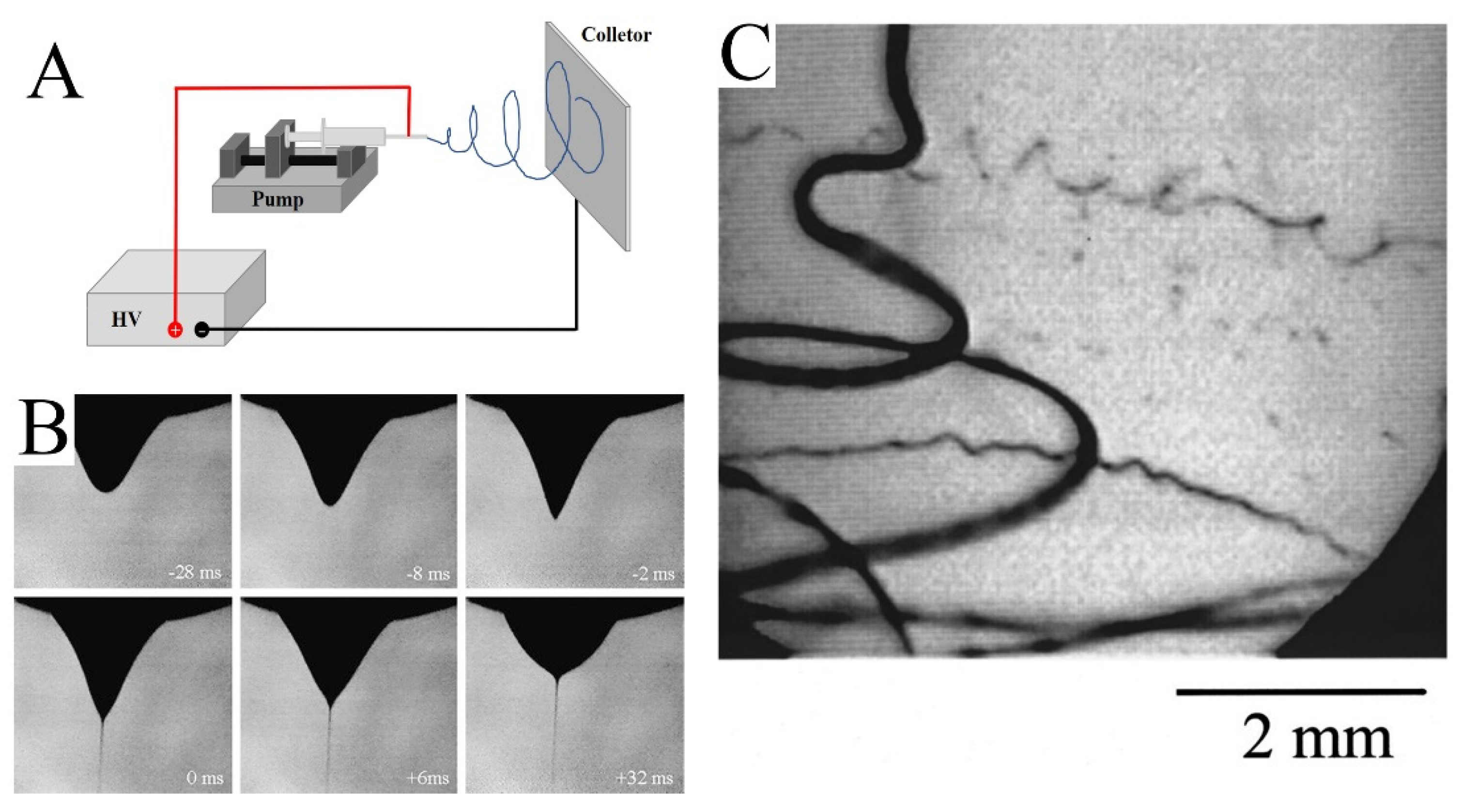
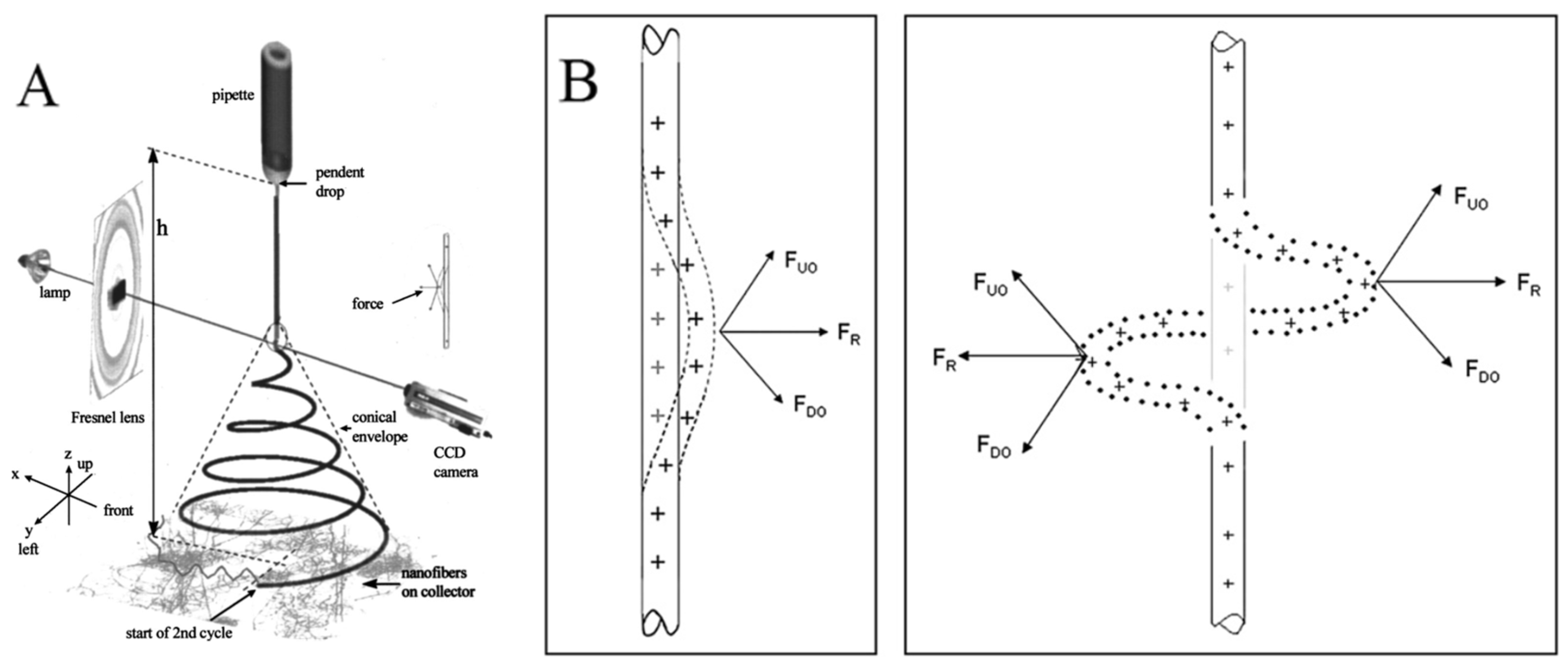

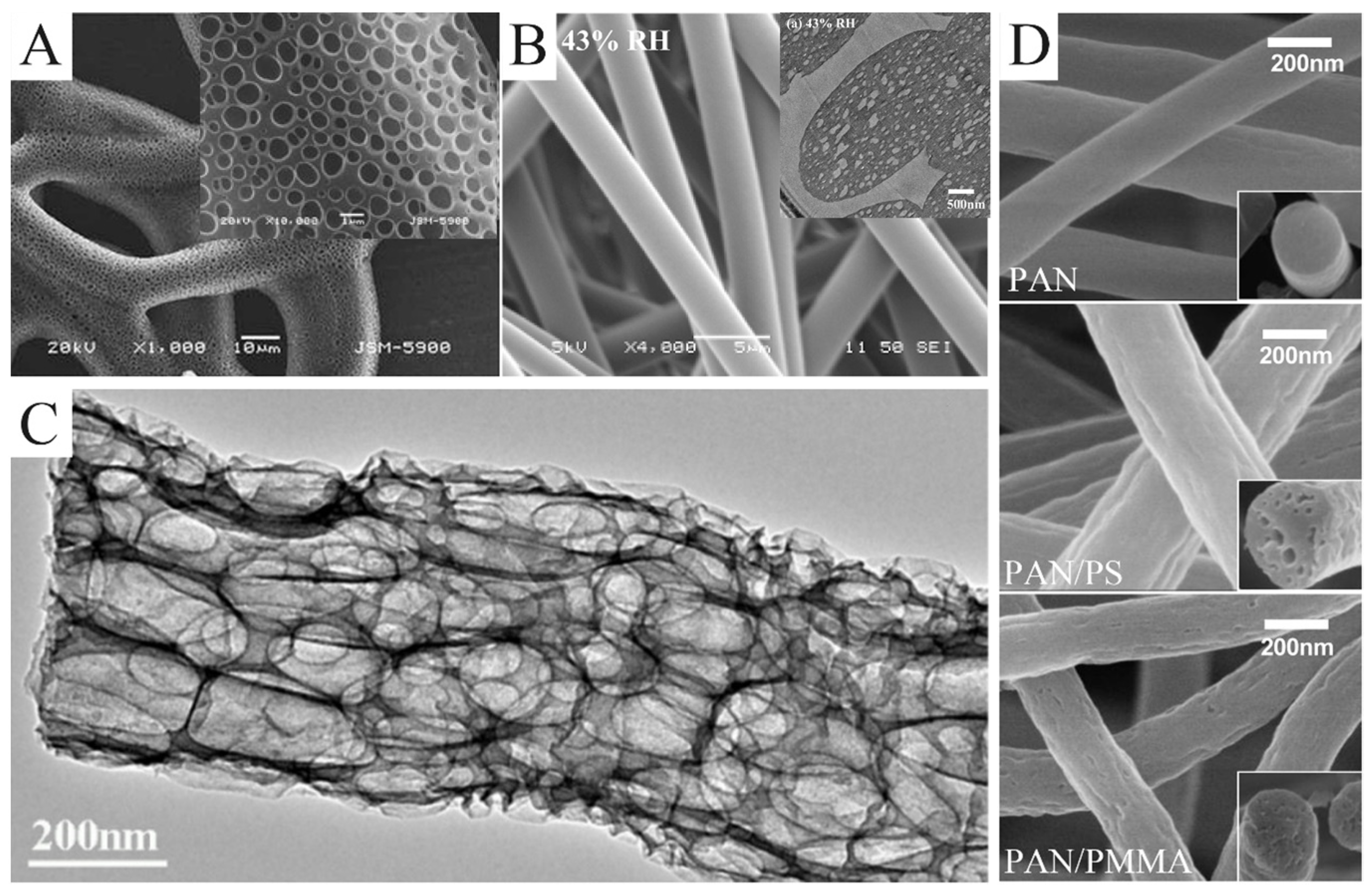
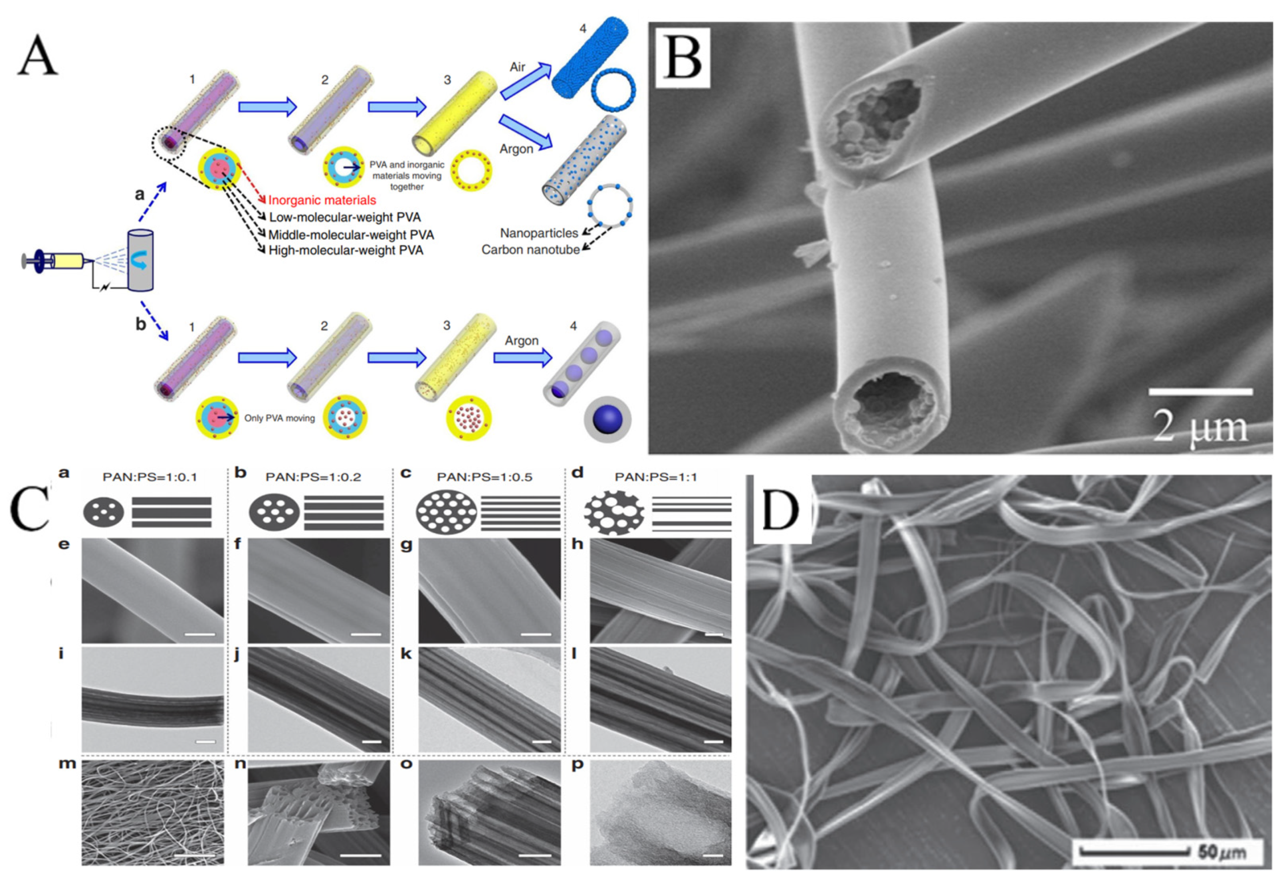
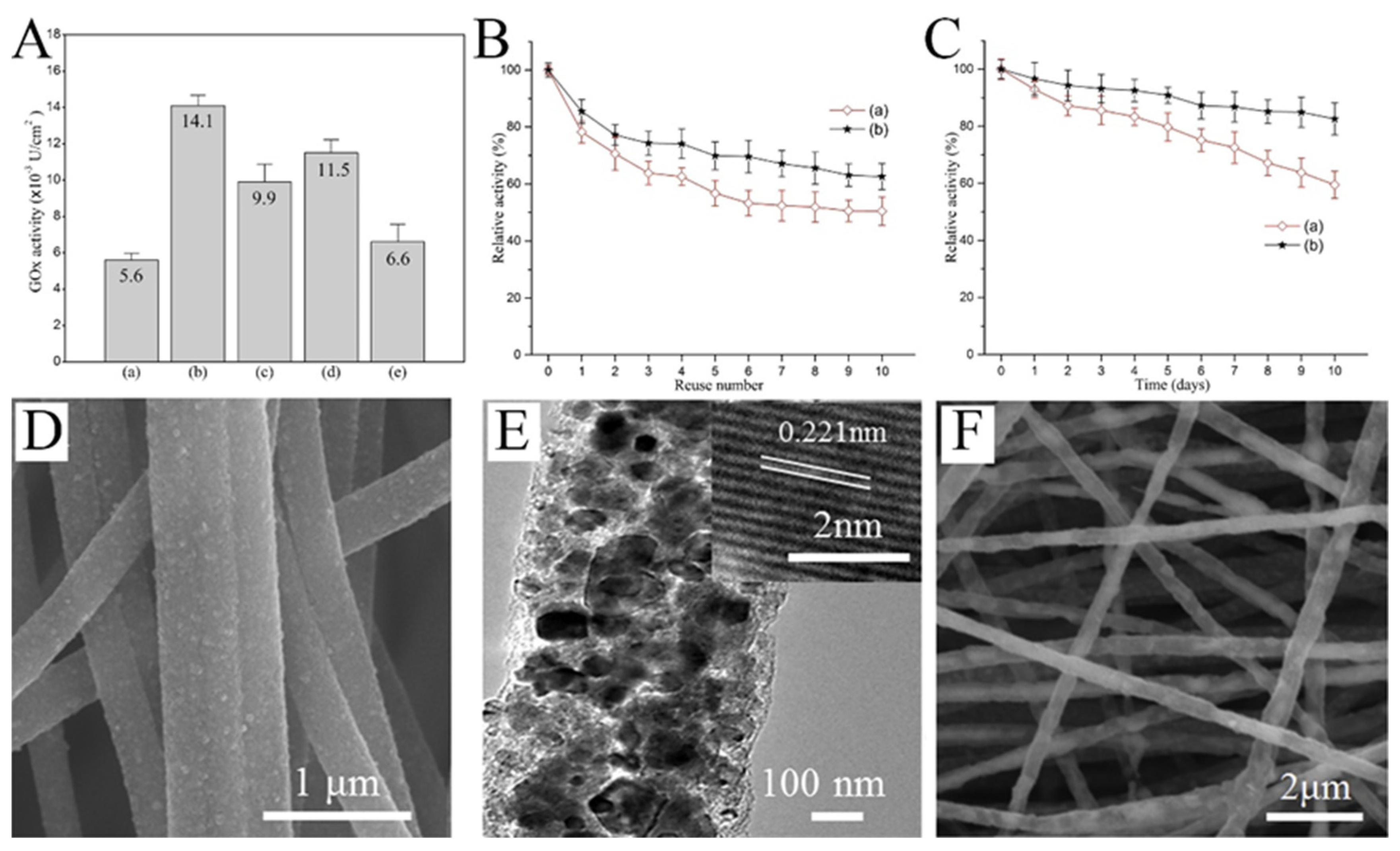
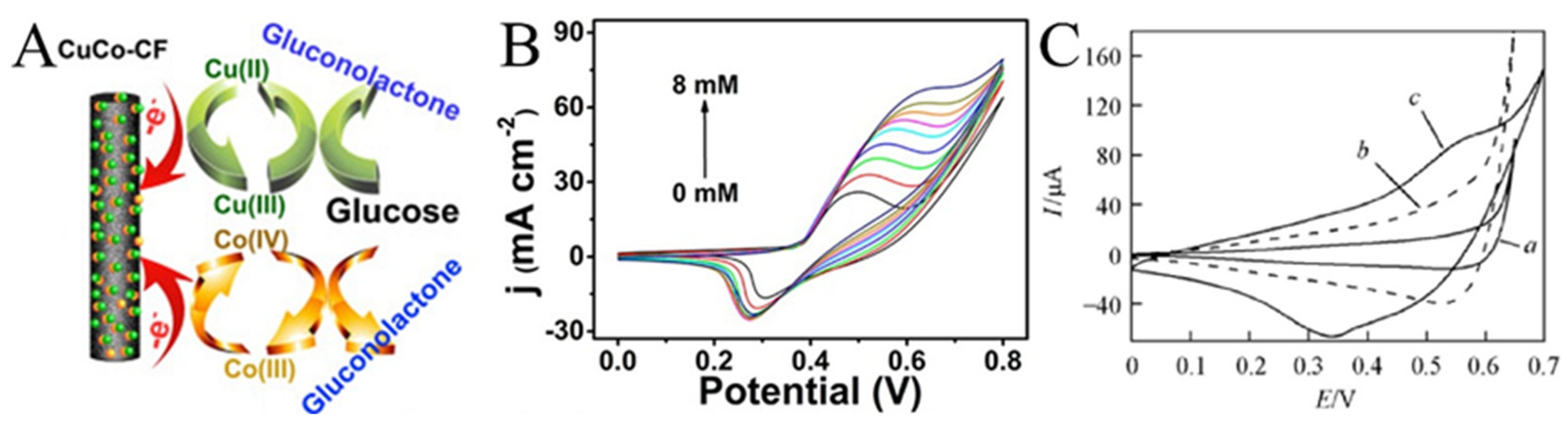
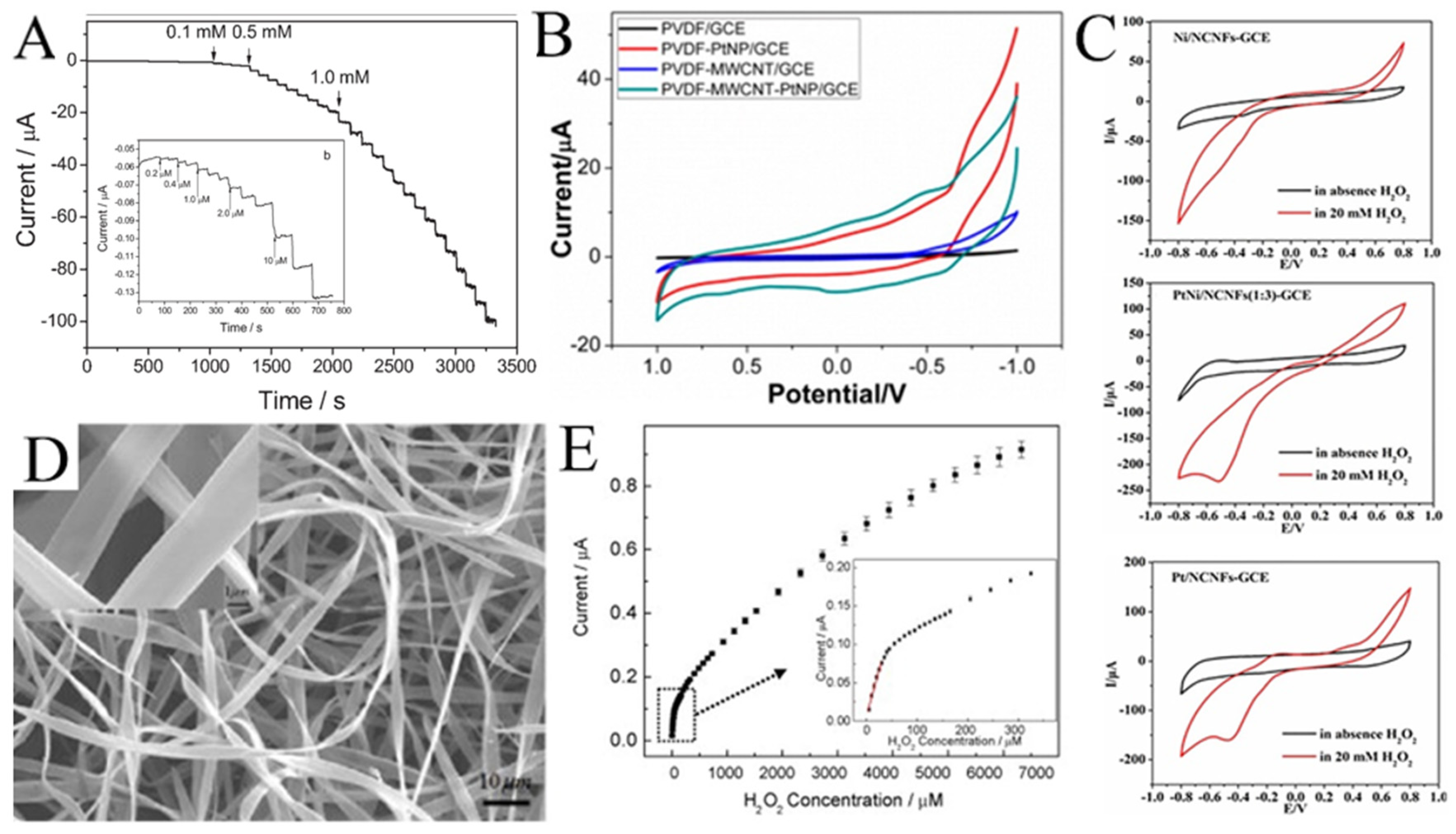

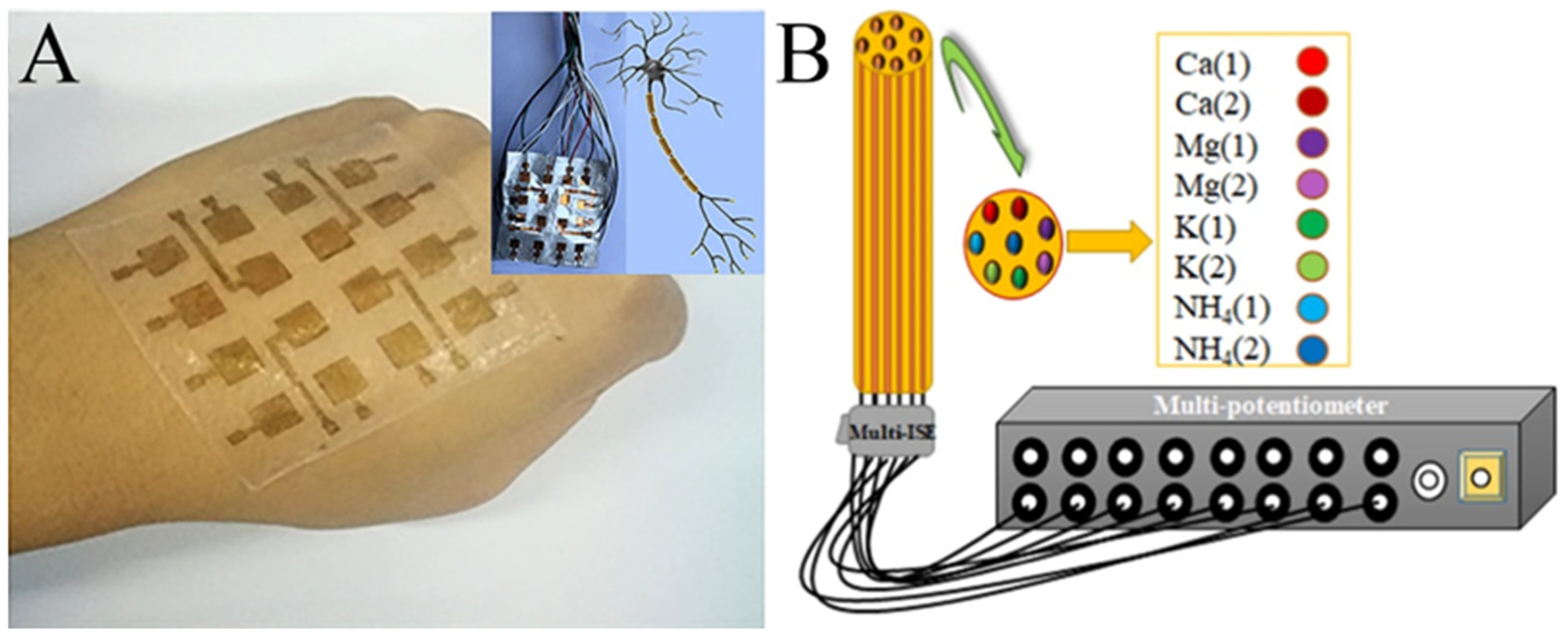
Disclaimer/Publisher’s Note: The statements, opinions and data contained in all publications are solely those of the individual author(s) and contributor(s) and not of MDPI and/or the editor(s). MDPI and/or the editor(s) disclaim responsibility for any injury to people or property resulting from any ideas, methods, instructions or products referred to in the content. |
© 2024 by the authors. Licensee MDPI, Basel, Switzerland. This article is an open access article distributed under the terms and conditions of the Creative Commons Attribution (CC BY) license (https://creativecommons.org/licenses/by/4.0/).