Abstract
Ni-based catalysts have been widely used for the CO2 reforming of methane (CRM) process, but deactivation is their main problem. This study created an alternative electronic Ni-NiO-CeO2 interaction on the surface of 5 wt% Ni-5 wt% CeO2/Al2O3-MgO (5Ni5Ce(xh)/MA) catalysts to enhance catalytic potential simultaneously with coke resistance for the CRM process. The Ni-NiO-CeO2 network was developed on Al2O3-MgO through layered double hydroxide synthesis via our ammonia vapor diffusion impregnation method. The physical properties of the fresh catalysts were analyzed employing FESEM, N2 physisorption, and XRD. The chemical properties on the catalyst surface were analyzed employing H2-TPR, XPS, H2-TPD, CO2-TPD, and O2-TPD. The CRM performances of reduced catalysts were evaluated at 600 °C under ambient pressure. Carbon deposits on spent catalysts were determined quantitatively and qualitatively by TPO, FESEM, and XRD. Compared to 5 wt% Ni-5 wt% CeO2/Al2O3-MgO prepared by the traditional impregnation method, the electronic interaction of the Ni-NiO-CeO2 network with the Al2O3-MgO support was constructed along the time of ammonia diffusion treatment. The electronic interaction in the Ni-NiO-CeO2 nanostructure of the treated catalyst develops surface hydroxyl sites with an efficient pathway of OH* and O* transfer that improves catalytic activities and coke oxidation.
1. Introduction
The unprecedented climate change mainly caused by greenhouse gases is becoming critical. Up to the present day, alternative sources of energy have been generated and developed to decrease greenhouse gas emissions [1,2]. The concentration of greenhouse gases is still at an all-time high. Carbon dioxide reforming of methane (CRM) (Equation (1)) is a significant catalytic process that commercially converts two key greenhouse gases (methane (CH4) and carbon dioxide (CO2)) into syngas, a gas mixture composed primarily of hydrogen (H2) and carbon monoxide (CO) [3,4,5]. The syngas produced with an approximately equal H2/CO ratio from the CRM process can be effectively utilized as a precursor for chemical industry production and for green fuel synthesis. In recent decades, Ni-based formulations have been considered as practical CRM catalysts because of their substantial activity with economic cost. However, fast and continuous deactivation is a critical issue for traditional Ni-based catalysts. During the reaction, Ni-based-catalyst-supported metal oxide can be impeded by metal sintering and coke deposition [6,7,8,9]. Over the catalyst surface, metal sintering is caused by a high operating temperature, while coke is formed and grown via side reactions, methane cracking (Equation (2)), and the Boudouard reaction (Equation (3)). Moreover, the side reaction that consumes H2 and causes the low H2/CO ratio in the syngas product is the reverse water–gas shift (RWGS, Equation (4)) [10,11].
CH4 + CO2 → 2H2 + 2CO △Ho298 K = +247 kJ/mol
CH4 → 2H2 + C △Ho298 K = +75 kJ/mol
2CO → CO2 + C △Ho298 K = +173 kJ/mol
H2 + CO2 → H2O + CO △Ho298 K = +41 kJ/mol
Several studies revealed how CeO2 improves the catalyst activity and stability of Ni-based catalysts. When CeO2 plays a vital role as a support for Ni-based catalysts, Ni sintering and coke deposition can be simultaneously resisted through the Ni-CeO2 interaction and oxygen storage properties of CeO2. Nonetheless, CeO2 has a low surface area compared to other available supports (Al2O3, MgO-Al2O3, SBA-15) [12,13,14]. As a promoter, the addition of CeO2 to a Ni/Al2O3 catalyst forms Ce1−XNiXO2 and CeAlO3 phases on the catalyst surface. Thus, the oxygen transfer and reducibility of the promoted catalyst can be improved to raise its catalytic activity and carbon resistance [15,16,17,18].
Our group has developed a novel ammonia vapor diffusion impregnation method that allows the size of the hierarchical nanostructures of the modified catalyst surface to be controlled by the ammonia vapor diffusion time. Previously, the hierarchical structure and basicity of the layered nanosheets on 10 wt% Ni/MgO-Al2O3 prepared by ammonia vapor diffusion impregnation for 20 h exhibited that the hierarchical nanostructures on the surface can enhance CO2 adsorption–dissociation and prevent coke formation for the CRM process [19]. A 10 wt% Ni-1 wt% ZrO2/Al2O3 catalyst prepared by a similar method with an ammonia diffusion time of 6 h demonstrated an improvement in the steam activation–dissociation and coke resistance for the combined steam and CO2 reforming of methane (CSCRM) process operated under low-temperature and low-steam conditions. This can be attributed to the very dispersive nanosheets and redox properties of the ZrO2 promoter that produces the number of the OH* and O* species on the surface [20]. Consequently, it would be interesting to develop the heterogeneity of Ni-CeO2 networks on catalyst surface through time-controlled ammonia diffusion treatment to investigate its effect on properties, CRM performance, and deactivation.
Herein, this present work prepared a 5 wt% Ni-5 wt% CeO2-supported MgO-Al2O3 catalyst by the ammonia vapor diffusion impregnation method (5Ni5Ce(xh)/MA). During the preparation, a nickel–cerium network nanostructure was initiated and grown during the ammonia diffusion treatment. Accordingly, two treatment times (6 h and 12 h) were applied to study the electronic effects of size and different network nanostructure morphologies on the catalyst surface. Thus, the physical properties were obtained via field emission scanning electron microscopy (FESEM), N2 physisorption analysis, and X-ray diffraction (XRD) analysis. The chemical insights into the surface interactions of the nanostructure on 5Ni5Ce(xh)/MA were evaluated by employing X-ray photoelectron spectroscopy (XPS), temperature-programmed reduction in H2 (H2-TPR), temperature-programmed desorption of H2 (H2-TPD), temperature-programmed desorption of O2 (O2-TPD), and temperature-programmed desorption of CO2 (CO2-TPD). The CRM catalytic performance was demonstrated in a tubular reactor at 600 °C for 16 h under atmospheric pressure. After the reaction, the carbon deposition was assessed using temperature-programmed oxidation (TPO), FESEM, and XRD. The above-mentioned effects on catalytic characteristics were elaborated and compared to the 5 wt% Ni-5 wt% CeO2-supported MgO-Al2O3 prepared by the traditional impregnation method (5Ni5Ce/MA).
2. Results and Discussion
2.1. Physical Properties
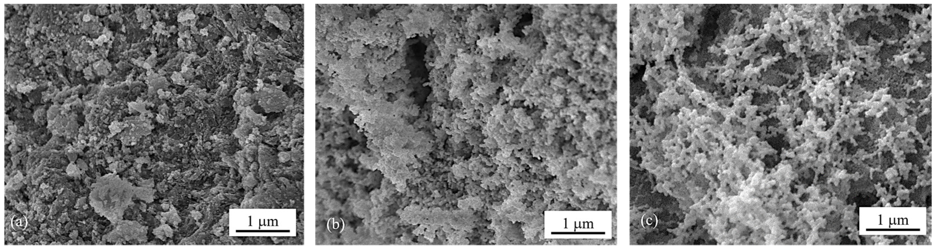
The surface morphologies of the calcined catalysts were investigated by means of FESEM images (Figure 1a–c) which show the changes in surface structure caused by ammonia vapor treatment. Compared to the morphology of 5Ni5Ce/MA (Figure 1a), the network of the metal oxide nanoparticles is generated over the surface of 5Ni5Ce(6 h)/MA (Figure 1b). This network of metal oxide nanoparticles is clearly visible on 5Ni5Ce(20 h)/MA (Figure 1c), implying the growth of the NiO-CeO2 interaction throughout the ammonia vapor diffusion. This can be explained by layered double hydroxide (LDH) synthesis via ammonia vapor diffusion impregnation [19,20,21]. When ammonia vapor is dissolved into the impregnated nickel–cerium nitrate solution on the support, a limited amount of hydroxide ions are produced, conducting the slow growth of the layered double hydroxide ([Ni1−-xCex(OH)2]z+(NO3)z·nH2O) throughout the diffusion time [22,23,24]. In this complex, metal ions are connected based on the inorganic layer as a multicomponent nanostructure. After calcination, the layer becomes a mixed-metal-oxide nanostructure.

Figure 1.
FESEM micrographs of calcined (a) 5Ni5Ce/MA, (b) 5Ni5Ce(6 h)/MA, and (c) 5Ni5Ce(20 h)/MA catalysts.
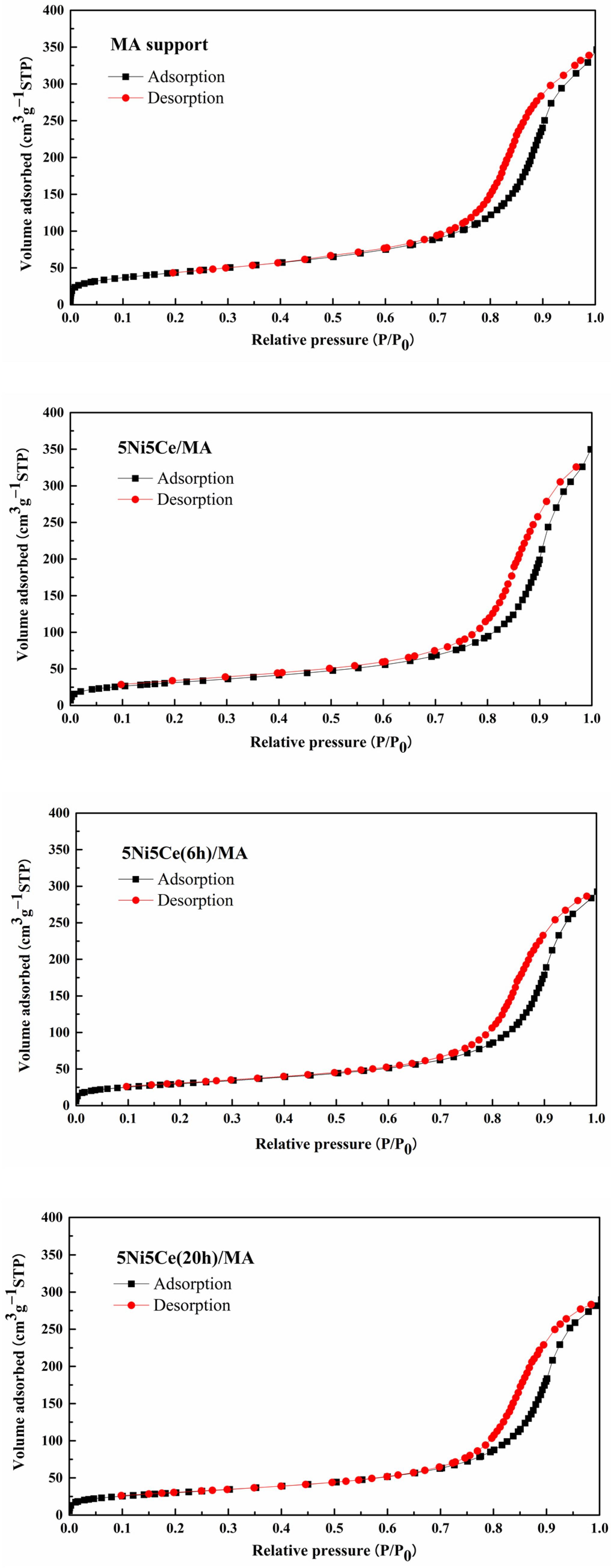
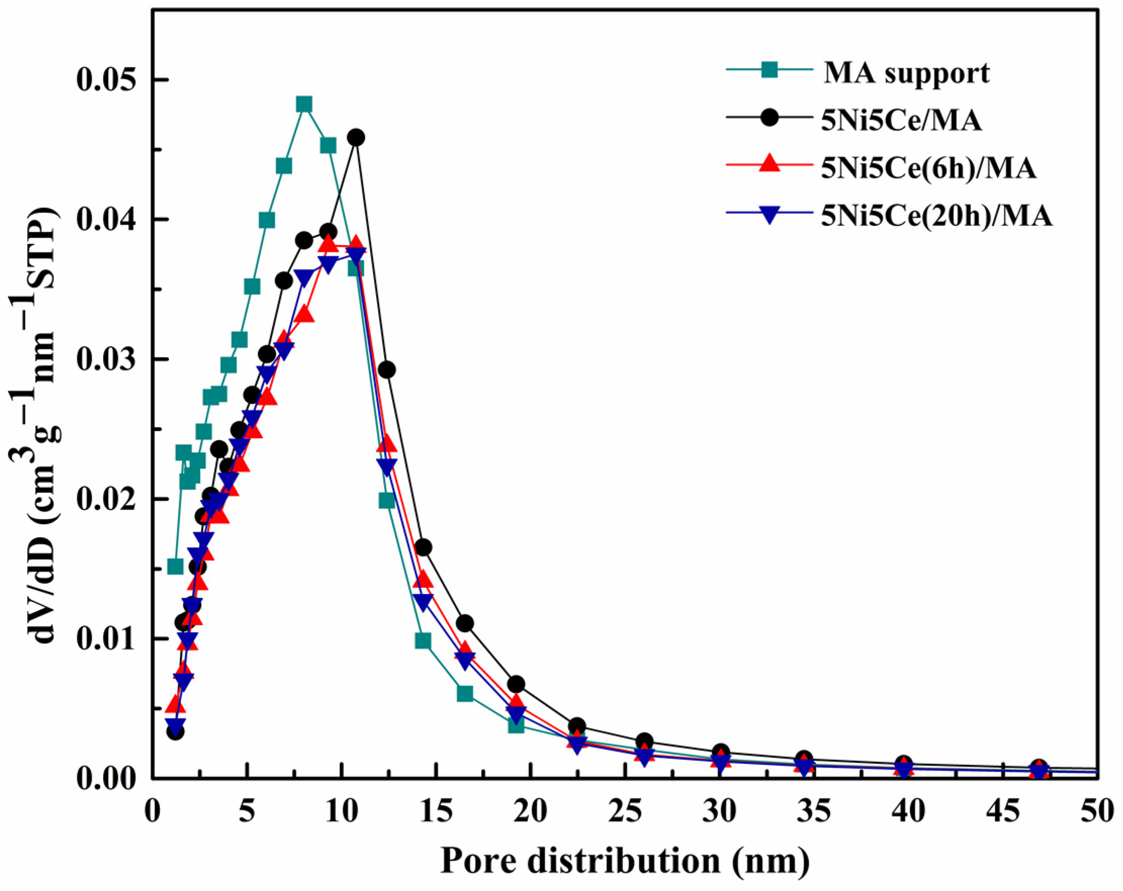
The textural properties of all samples were examined using N2 adsorption–desorption measurements. The isotherm patterns of all samples (Figure 2) exhibit a type IV(a) isotherm feature of mesoporous materials with the combination of H2(b) and H3 hysteresis loops (IUPAC), correlating to the connection of the bottleneck-shaped and plate-shaped pores in the relative pressure range (P/P0) of 0.60–1.00 [25,26,27,28]. Using the BJH method, the pore size distribution curves of all samples are established in Figure 3. Table 1 reports the average pore size diameter estimated from the BJH method and the surface area with the total pore volume calculated from the BET equation. The support and catalyst samples show an average pore size diameter smaller than 25.0 nm. The surface of the MA support has an area of 151 m2 g−1 with an average pore size diameter of 8.0 nm and a total pore volume of 0.52 cm3 g−1. When 5 wt% Ni and 5 wt% CeO2 were loaded onto the MA support (5Ni5Ce/MA), the surface area decreased to 108 m2 g−1 with a total pore volume of 0.51 cm3 g−1, whereas the average pore size diameter increased to 10.8 nm. These results can be explained by the blockage of smaller pores of the MA support by large nanoparticles [29,30]. Considering the ammonia vapor diffusion impregnation of 5 wt% Ni and 5 wt% CeO2 for 6 h (5Ni5Ce(6 h)/MA) and 20 h (5Ni5Ce(20 h)/MA), the surface area and total pore volumes of these two catalysts are similar (101 m2 g−1 and 0.43–0.44 cm3 g−1, respectively). These values of the textural properties are lower than 5Ni5Ce/MA due to the stronger blocking effect caused by the growth of the mixed-oxide nanoparticles.
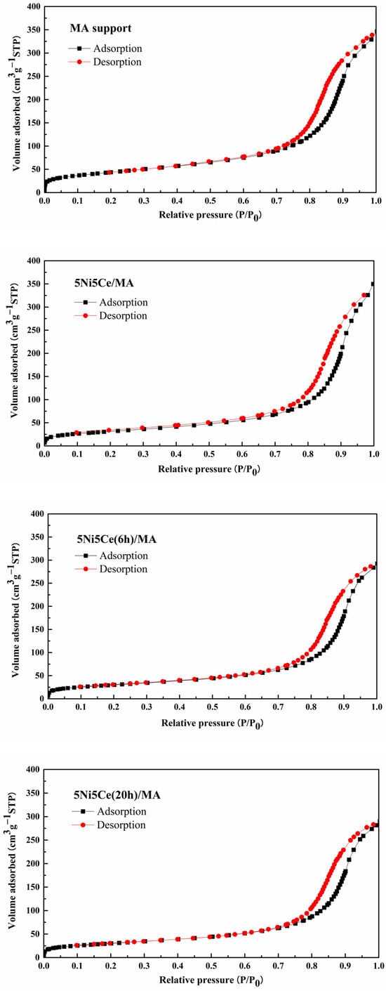
Figure 2.
N2 adsorption–desorption isotherms of support and all calcined catalysts.
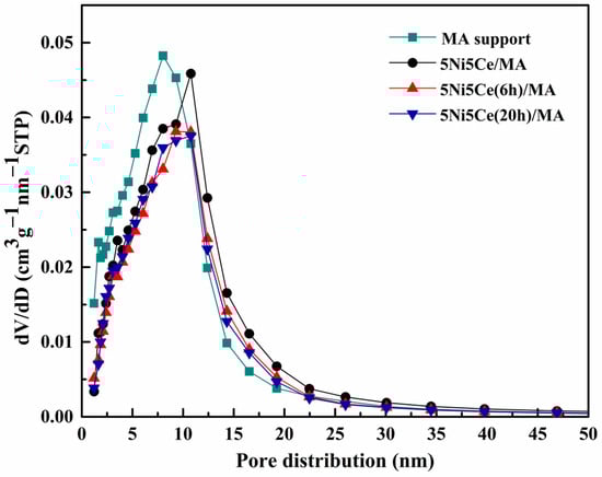
Figure 3.
BJH pore size distributions of support and all calcined catalysts.

Table 1.
Bulk and surface properties of support and all calcined catalysts.
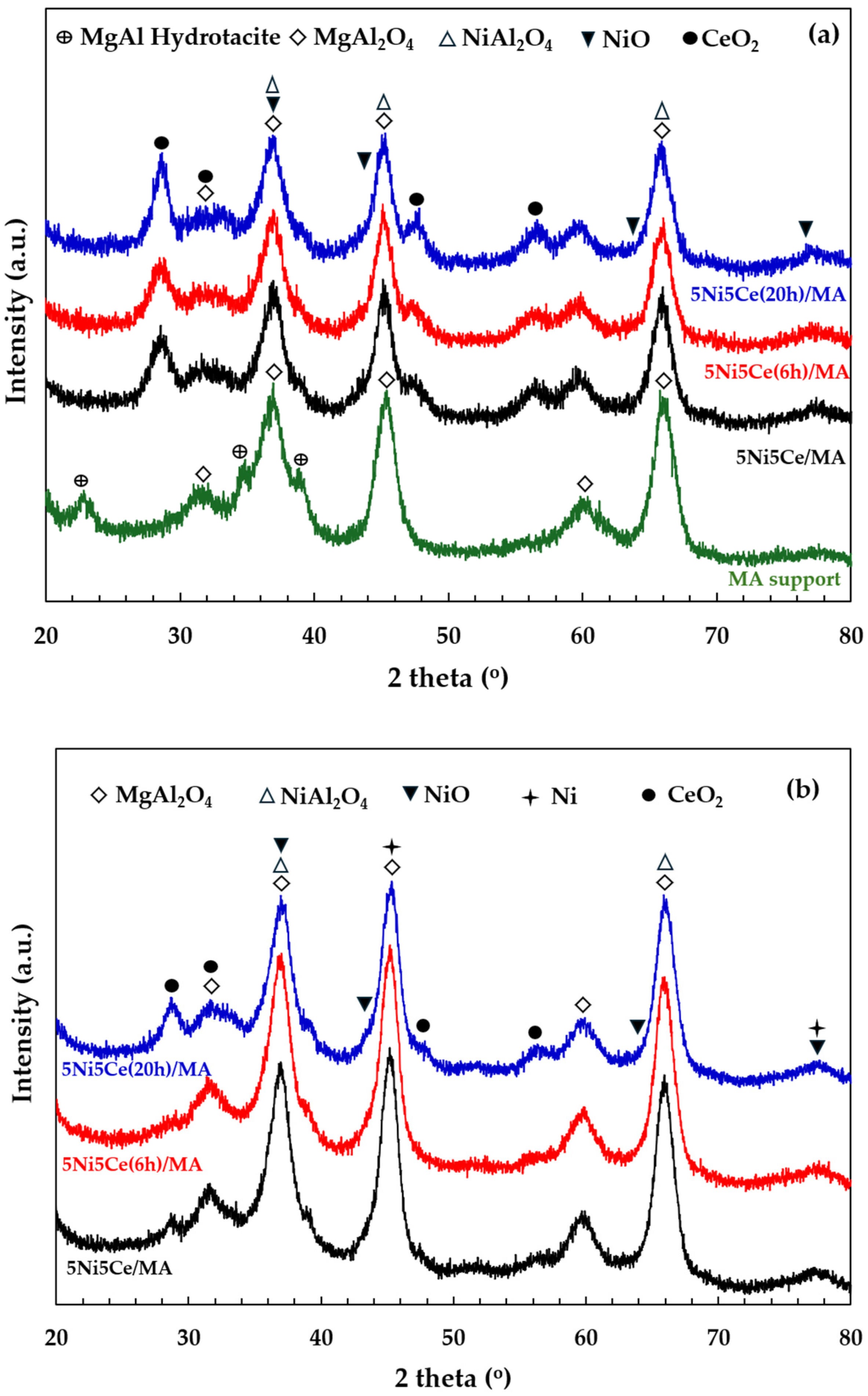
The X-ray diffraction patterns of the MA support, calcined catalysts, and reduced catalysts are presented in Figure 4. According to Figure 4a, the diffractogram of the MA support represents the peak patterns of the MgAl hydrotalcite phase (JCPDS No. 022-0700) and the MgAl2O4 spinel structure (JCPDS No. 01-084-0377) [31,32,33,34]. After calcination in the catalyst preparation, the MgAl hydrotalcite phase is completely transformed into the MgAl2O4 spinel phase, as the pattern of MgAl hydrotalcite cannot be observed in the diffractograms of the calcined catalysts (Figure 4a). When the 5 wt.% Ni and 5 wt.% CeO2 were impregnated onto the MA support, the pattern of the spinel phase could also be attributed to the occurrence of NiAl2O4 (JCPDS No. 10-0339) on all of the calcined catalysts. This pattern overlaps with the diffraction peaks of MgAl2O4 spinel and NiO crystalline phase (JCPDS No. 47-1049). Likewise, nickel oxide phases and the nickel metal phase (JCPDS No. 04-0850) are seldom identified in the diffractograms of the reduced catalysts (Figure 4b) due to the overlapping peaks in the patterns of various nickel crystalline systems [35,36,37]. Thus, the nickel species on the reduced catalysts were investigated via XPS characterization. Differently, the peak patterns of CeO2 (JCPDS No. 43-1002) were detected in the diffractograms of all the calcined catalysts and reduced catalysts [38,39,40,41]. For a quantitative comparison, the CeO2 crystallite sizes on the calcined catalysts (Table 1) were determined via Scherrer’s equation at 2 theta = 28°. Compared to the calcined 5Ni5Ce/MA, the average CeO2 crystallite size slightly decreased when the catalyst was treated in ammonia vapor for 6 h, indicating a greater distribution of the NiO-CeO2 nanostructure. Contrarily, the crystallite size of CeO2 on the surface increased when the catalyst was treated in ammonia vapor for 20 h, implying the growth of a mixed-metal-oxide nanostructure during the time of treatment. Although the crystallite sizes of CeO2 on the reduced catalysts were smaller than those of the calcined catalysts due to the partial reduction in CeO2, the same CeO2 crystallite size trend was observed on the reduced catalysts.
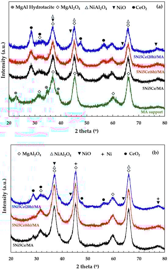
Figure 4.
The X-ray diffraction patterns of (a) MA support and calcined catalysts, and (b) reduced catalysts.
2.2. Chemical Properties
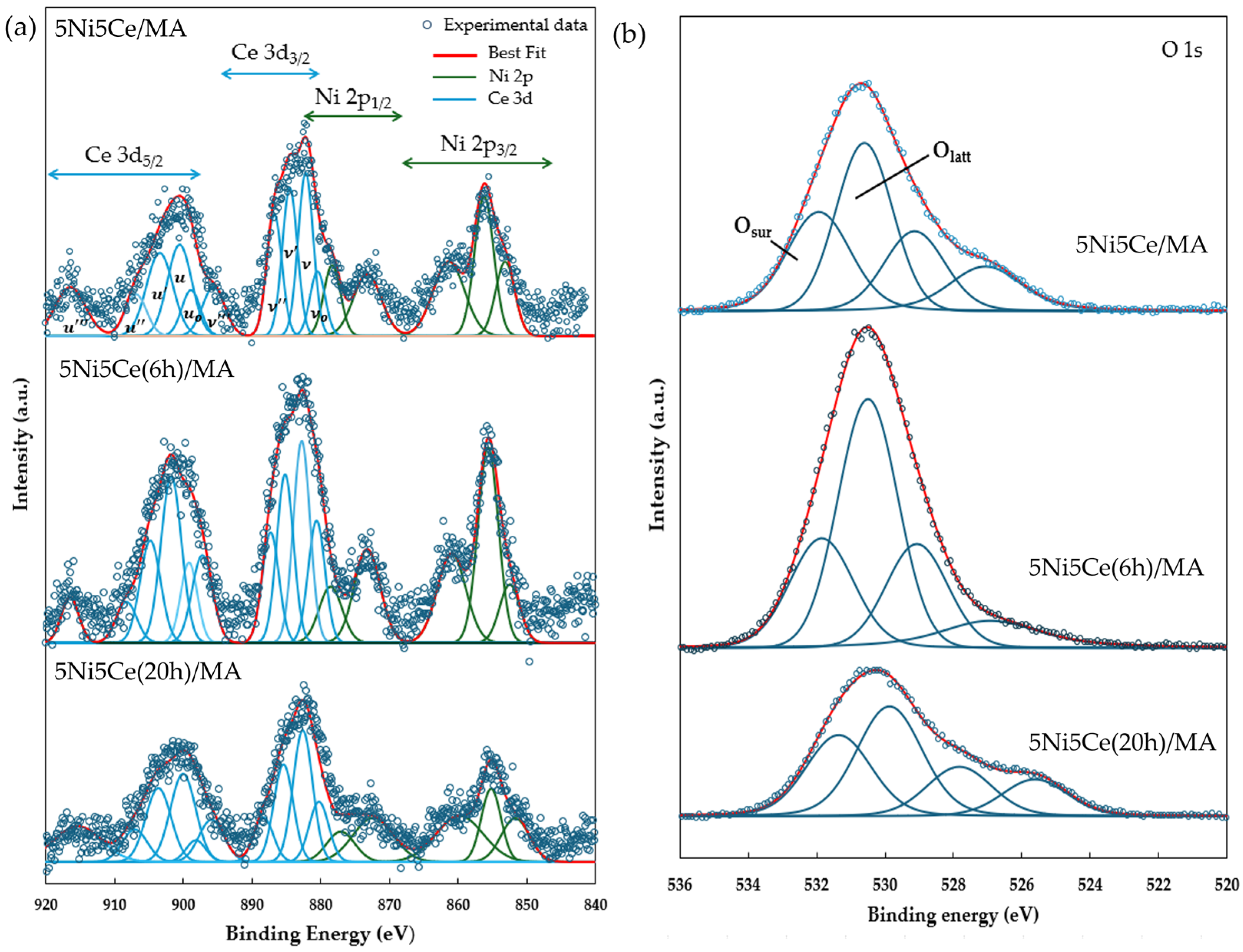
The reduction profiles of the oxide species (Figure 5) were carried out by the H2 temperature program reduction (H2-TPR) to determine the reducibility and the interaction among the components of the calcined catalysts. The H2-TPR profiles of all the calcined catalysts demonstrate two temperature reduction ranges. The reductions at lower temperature ranging from 250 °C to 450 °C correspond to the NiO species poorly interacting with other components and the partial reduction in CeO2. The reduction peaks at temperatures higher than 500 °C are assigned to the moderate-to-strong interaction of NiO-CeO2 and NiO-CeO2-MA and the formation of spinel oxides such as NiAl2O4 due to the strong metal–support interaction (SMSI) effect [42,43,44,45,46,47]. The XPS spectra of Ni 2p + Ce 3d (Figure 6a) and O 1s (Figure 6b) were obtained to investigate the chemical states of Ni and Ce on the surface of all ex situ reduced catalysts. In Figure 6a, the Ni 2p core level spectra show the presence of metallic Ni (Ni0) at a binding energy (BE) of 851.7–852.9 eV, and Ni2+ at a BE of 855.2–855.9 eV. The Ce 3d core level spectra show the co-existence of Ce4+ (blue peaks = v, v″, v‴, u, u″, and u‴) and Ce3+ (blue peaks = v0, v′, u0, and u′) [48,49,50,51]. The O 1s peak (Figure 6b) was deconvoluted to identify the oxygen species of the reduced catalysts. The peaks of lattice oxygen (Olatt) in NiO, CeO2, NiAl2O4, and the MA support was found at a BE of about 530 eV. The peaks of surface oxygen (Osur) based on oxygen vacancies and hydroxyl were observed at higher BE values (531–532 eV) [52,53]. The relative concentration of metallic nickel Ni ([Ni0]/[Ni0] + [Ni2+]), the relative concentration of Ce3+ ([Ce3+]/[Ce4+] + [Ce3+]), and the Osur/Olatt ratio were then evaluated from their peak areas (Table 2).
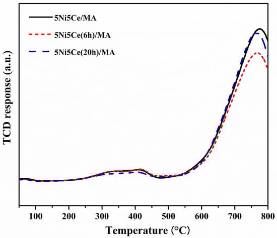
Figure 5.
H2-TPR profiles of all reduced catalysts.
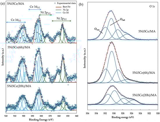
Figure 6.
XPS core level spectra of reduced catalysts in (a) Ni 2p + Ce 3d energy region and (b) O 1s energy region.
Table 2.
Chemical state analysis of Ni 2p, Ce 3d, and O 1s from XPS spectra.
According to the H2-TPR profiles and XPS results, the maximum hydrogen consumption with the reduction curve at the highest temperature and the maximum relative concentrations of Ni0 and Ce3+ with the highest Osur/Olatt ratio were obtained from the untreated 5Ni5Ce/MA catalyst. These results indicate the greatest reductions in nickel oxide (NiO or NiAl2O4 → Ni0) and CeO2 (CeO2 (Ce4+)→ Ce2O3 (Ce3+), generating oxygen vacancies) with the presence of spinel phases due to the SMSI effect on the surface of the untreated 5Ni5Ce/MA catalyst. The reduction peak slightly shifts to a lower temperature with the minimum hydrogen consumption on 5Ni5Ce(6 h)/MA. The smallest amount of nickel oxide reduction was confirmed by the lowest Ni0 fraction with the lower partial CeO2 reduction (XPS result). This is owing to the high dispersion of the initiated NiO-CeO2 nanoparticles on the MA support during the short treatment process. Therefore, the SMSI effect still presents, and the tiny nanoparticles cause some nickel oxide particles to merge completely into the MA support underneath the surface with the NiO-CeO2 interaction. Consequently, these deduct the reductions in nickel oxide as well as in CeO2 and show a greater Olatt portion on the surface. When treated by ammonia vapor a for longer time (5Ni5Ce(20 h)/MA catalyst), the NiO-CeO2 network (SEM image) constructed on the surface increases nickel oxide in the mixed-oxide nanoparticles and decreases the isolated CeO2. Compared to 5Ni5Ce(6 h)/MA, hydrogen consumption at a high temperature range and the relative concentration of Ni0 increases while the relative concentration of Ce3+ decreases on 5Ni5Ce(20 h)/MA. Considering the quantity of Ni0, the hydrogen consumption profiles of H2-TPR of 5Ni5Ce/MA and 5Ni5Ce(20 h)/MA are almost similar, while the Ni0 relative concentrations are different. This indicates the number of Ni2+ in other forms. For the treated catalyst with which the surface was constructed in the LDH formation for a long time, the NiO-CeO2 mixed oxide increased the Ni2+ on the surface, forming Ni(OH)2 and NiO. Moreover, only NiO at the uppermost level can be reduced. Therefore, 5Ni5Ce(20 h)/MA shows a higher Osur/Olatt ratio than that of 5Ni5Ce(6 h)/MA.
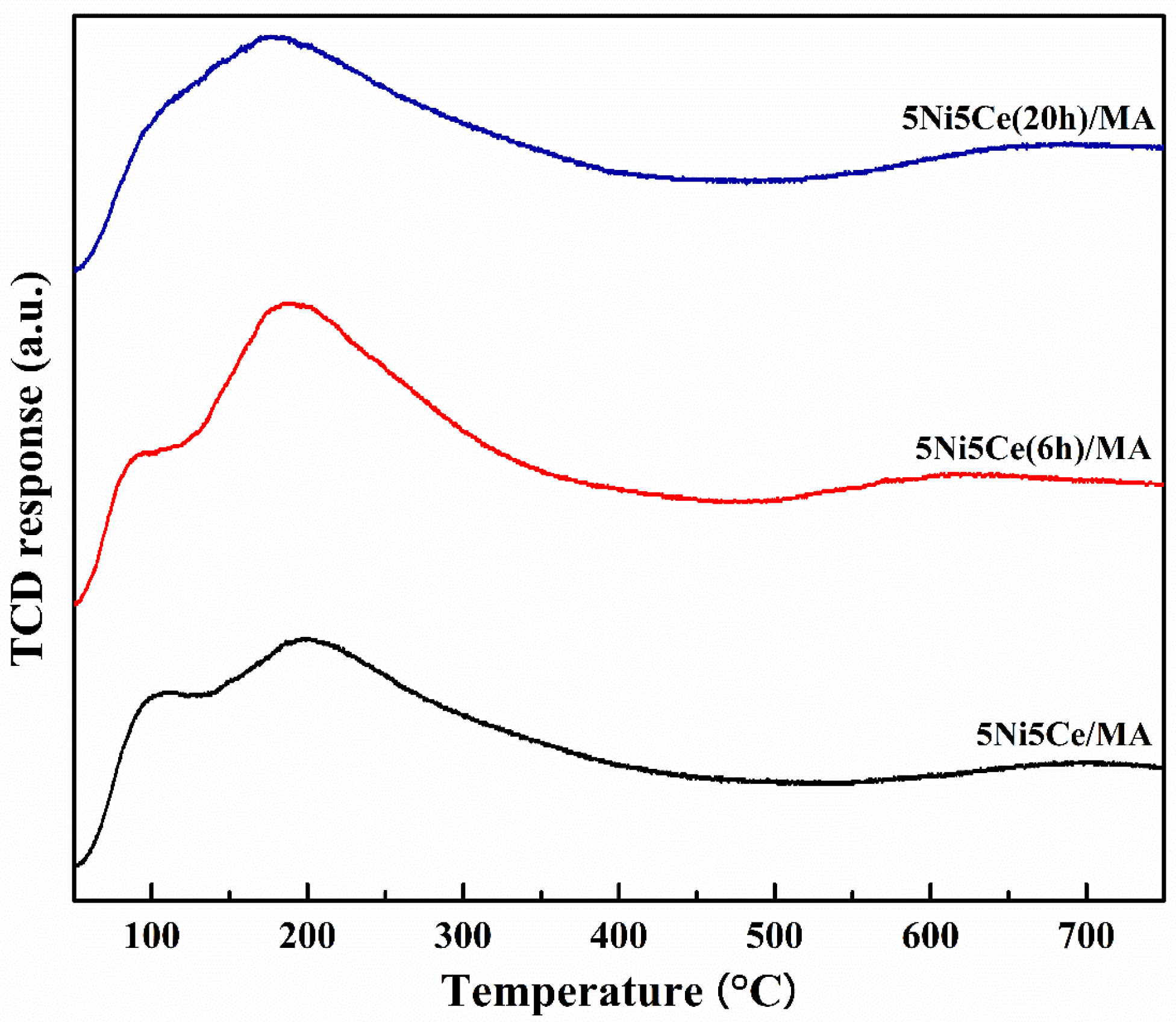
The metal particle size distributions, including the metal surface layers of the reduced catalysts, were determined via H2-TPD measurement. Two desorption temperature ranges were observed in the profiles (Figure 7), suggesting a weak hydrogen chemisorption on the Ni metal at the top layer (temperature lower than 180 °C) and the medium–strong hydrogen chemisorption on the Ni metal interacting with the support, contributing to the hydrogen spillover onto the catalyst support (temperatures higher than 180 °C) [54,55,56]. The amount of hydrogen desorption was determined as reported in Table 3. The H2-TPD profiles of the reduced catalysts represent different arrangements of Ni metal active sites on the surface. The largest hydrogen desorption at a high temperature range and the smallest hydrogen desorption at a low temperature range were obtained from the untreated catalyst, implying that most Ni metal active sites interacted with the support. The 5Ni5Ce(6 h)/MA catalyst possesses the largest amount of H2 desorption, representing the highest Ni dispersion. According to the H2-TPD profiles of the treated catalysts, the hydrogen desorption at high temperature ranges trends to decrease, while the hydrogen desorption at low temperature ranges trends to increase when the duration of the ammonia diffusion treatment increases. These results suggest the raising of the Ni metal active sites on the uppermost surface layer due to the growth of the NiO-CeO2 layer on the surface, which reduces the interaction of active sites with the support.
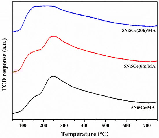
Figure 7.
H2-TPD profiles of all reduced catalysts.
Table 3.
The amount of H2 desorption on all reduced catalysts.
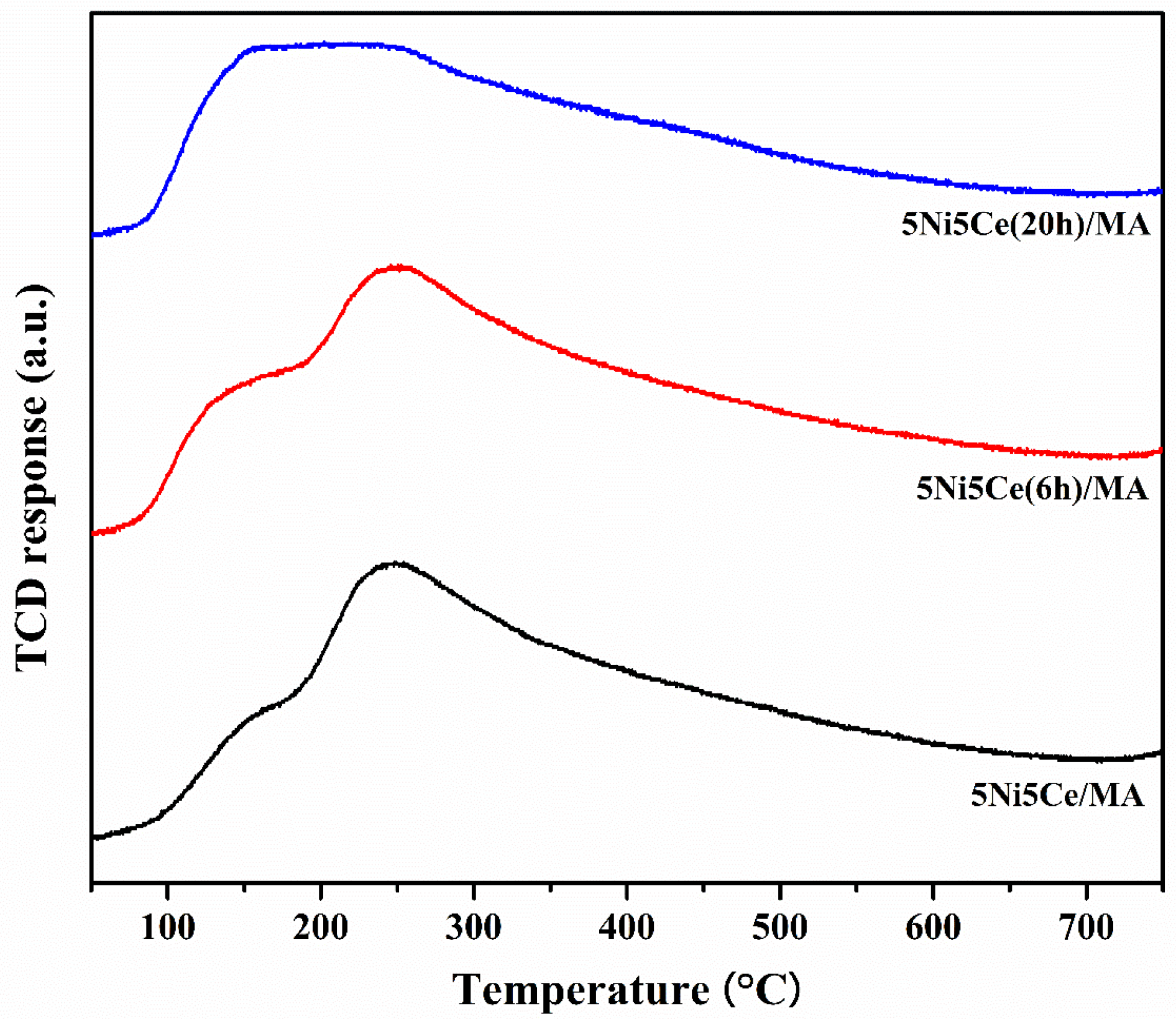
The amount and strength of the basic sites on the reduced catalysts related to the catalytic activity of CO2 were identified by CO2-TPD (Figure 8). The strength of the basic sites can be distinguished by the temperature corresponding to the desorption of CO2. The basic sites of reduced 5Ni5Ce/MA, 5Ni5Ce(6 h)/MA, and 5Ni5Ce(20 h)/MA catalysts demonstrate three temperature ranges of CO2 desorption. The weak basic sites in the low temperature range of 50–150 °C can be ascribed to Brønsted OH− groups on the surface, the moderate basic sites (150–400 °C) are attributed to metal–oxygen pairs (Lewis basic site), and the strong basic sites at temperatures higher than 400 °C are assigned to the surface of low coordinated O2− anions [57,58,59]. Among all the strengths of the basic sites, the Brønsted OH– and Lewis basic sites are clearly observed on all reduced catalysts. Table 4 reports the deconvoluted quantities of CO2 desorption from all reduced catalysts. Accordingly, the treated catalysts present a greater number of Brønsted OH− sites than the untreated 5Ni5Ce/MA catalyst, and this type of basic site tends to increase with the duration of treatment. This can be explained by the effect of surface modification by treatment in ammonia vapor diffusion, which composes the surface through the LDH structure and involves the rehydration property (memory effect) after calcination.
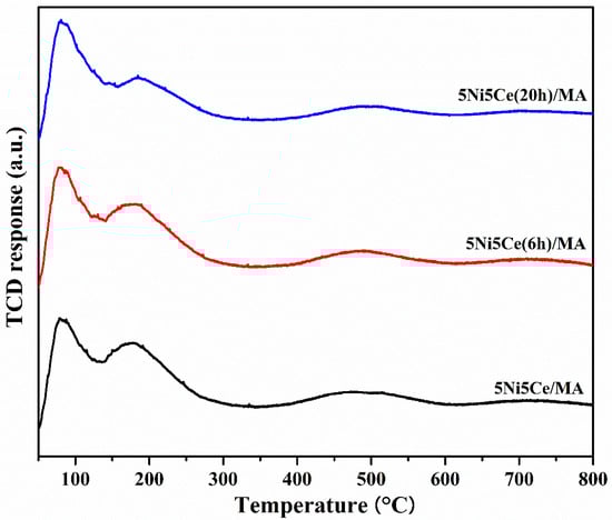
Figure 8.
CO2-TPD profiles of all reduced catalysts.
Table 4.
The amount of CO2 desorption on all reduced catalysts.
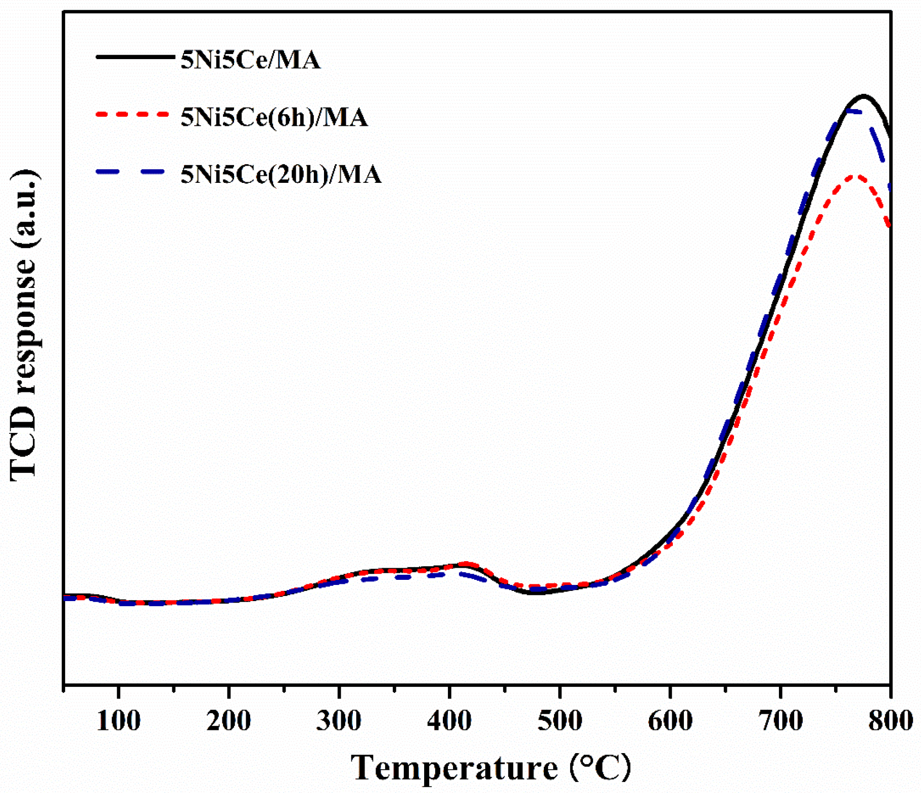
The oxygen mobility in all reduced catalysts was further evaluated by O2-TPD measurement (Figure 9) at a temperature range from 50 °C up to 800 °C. The oxygen transfer on the catalyst can be predicted via the O2-TPD profile. The oxygen desorption peaks at low temperature are assigned to surface oxygen, including physiosorbed oxygen molecules and oxygen from oxygen vacancies (resulting from the redox property of Ce4+/Ce3+). At the higher temperature range, the desorption peaks are attributed to lattice oxygen [16,60,61,62,63,64,65]. The oxygen desorption quantities according to the various types of oxygen mobility were calculated (Table 5). The O2-TPD results may be relative to the XPS analysis. The 5Ni5Ce/MA catalyst shows two desorption peaks at different ranges of temperature. Compared to 5Ni5Ce/MA, the catalyst treated in the ammonia vapor for 6 h (5Ni5Ce(6 h)/MA catalyst) presents less surface oxygen and more lattice oxygen due to the good dispersion of small NiO-CeO2 nanoparticles initiated on the surface. For the comparison of treated catalysts (6 h and 20 h), surface oxygen increases, lattice oxygen decreases, and the peaks of surface and lattice oxygen merge smoothly in the O2-TPD profile of 5Ni5Ce(20 h)/MA. These results indicate the connection of the surface and lattice oxygen through the electronic interaction of Ni-NiO-CeO2 produced by 20 h ammonia vapor treatment.
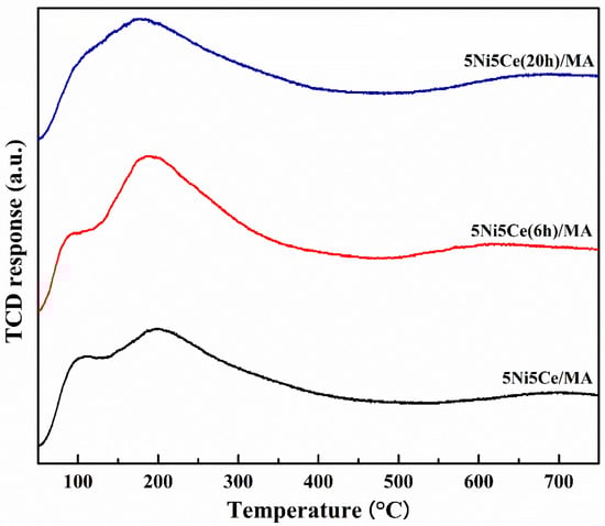
Figure 9.
O2-TPD profiles of all reduced catalysts.
Table 5.
The amount of O2 desorption on all reduced catalysts.
2.3. Catalytic Performance and Coke Resistance
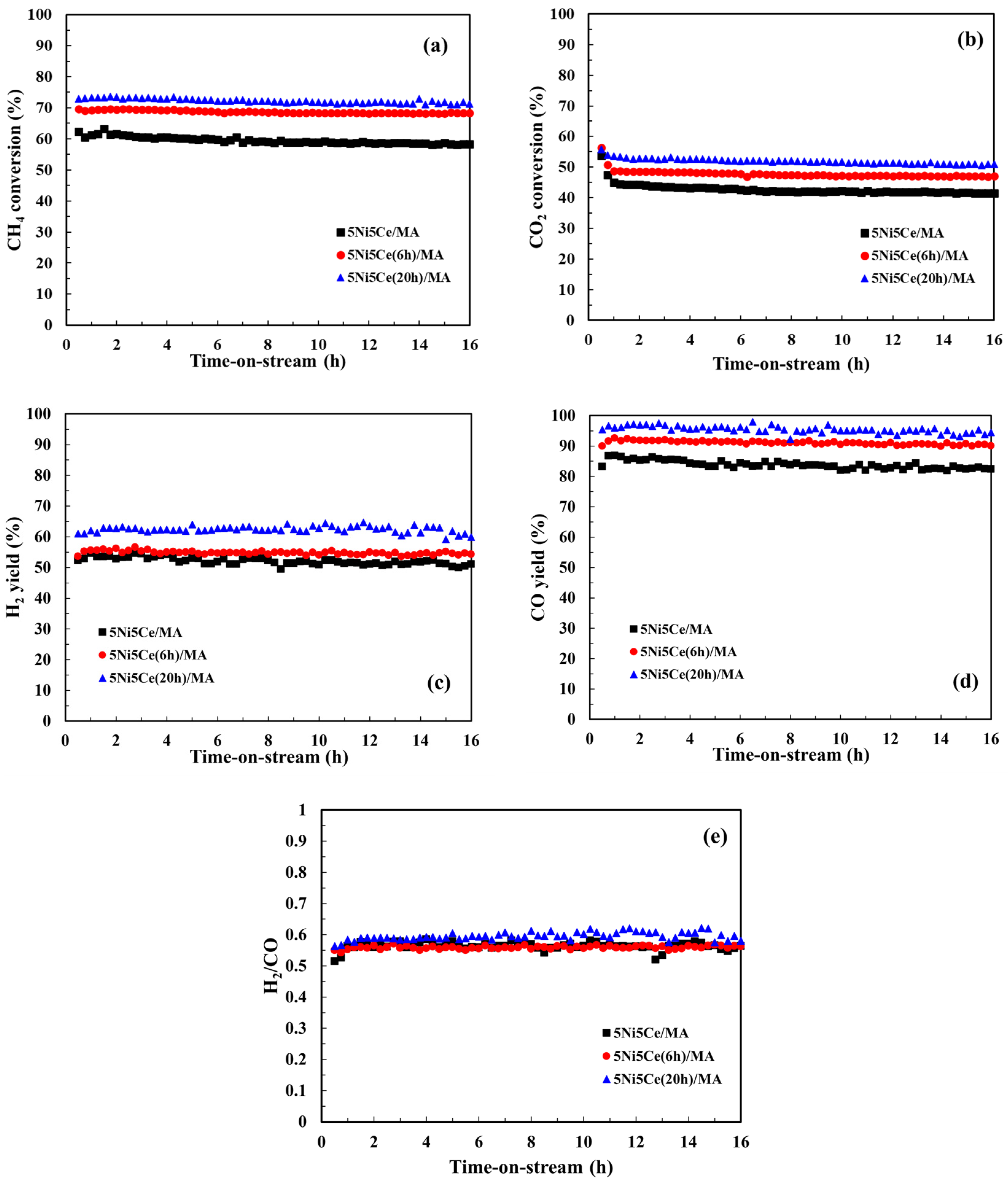
The CMR catalytic behaviors of the 5Ni5Ce/MA and treated 5Ni5Ce(xh)/MA catalysts were investigated at 600 °C under atmospheric pressure for 16 h. The performance was evaluated by means of CH4 conversion, CO2 conversion, and the H2/CO ratio of the syngas product (Figure 10). The 5Ni5Ce/MA catalyst presents an average CH4 conversion of 59.4%, an average CO2 conversion of 43.5%, and a H2/CO ratio of 0.58 (H2 yield = 51.8% and CO yield = 82.7%). Compared to 5Ni5Ce/MA, the 5Ni5Ce(6h)/MA catalyst reflects the relative higher activity toward CH4 conversion (68.8%) and CO2 conversion (47.9%) with similar H2/CO ratio of 0.56 (H2 yield = 54.8% and CO yield = 90.9%). The highest CH4 conversion of 72.2%, the highest CO2 conversion of 52.1%, and a H2/CO ratio of 0.59 (H2 yield = 62.3% and CO yield = 95.3%) were obtained from the 5Ni5Ce(20h)/MA catalyst. The enhancement of reactant activities as well as product yields on 5Ni5Ce(20h)/MA can be attributed to the number of active sites in the Ni-NiO-CeO2 network. As observed in CO2-TPD, these Ni-NiO-CeO2 nanostructures develop their electronic interactions with the nanostructure over the course of treatment. The surface hydroxide on the structure increases the turnover frequency of CO2 on the Ni-NiO-CeO2 network, agreeing with the CO2-TPD measurement. These surface hydroxyl sites allow Ni metal sites to be active toward CH4. For the CO yield values in which CH4 and CO2 consumptions were considered, the treated catalysts had smaller amounts of carbon deposition than the untreated catalyst. The coke deposition analysis is discussed in the following part. Moreover, the highest H2 yield (62.3%), the highest CO yield (95.3%) and the slightly higher H2/CO ratio (0.59) observed on the 5Ni5Ce(20 h)/MA catalyst imply a reduced RWGS side reaction effect. This is assigned to the rehydration property promoting H2O adsorption–dissociation [20].
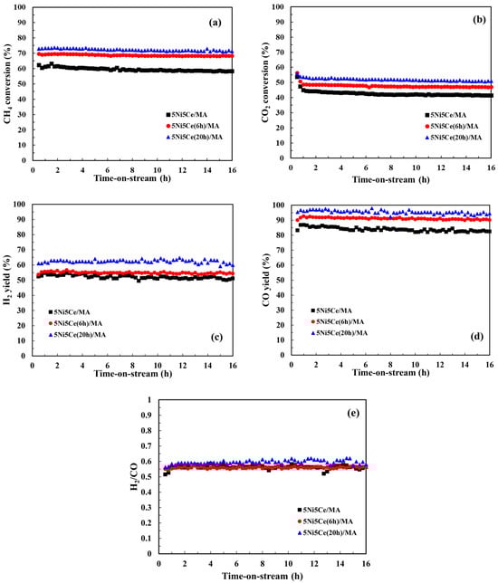
Figure 10.
(a) CH4 conversion, (b) CO2 conversion, (c) H2 yield, (d) CO yield, and (e) H2/CO ratio for the CO2 reforming of methane (CRM) of all catalysts. Reaction conditions: 600 °C and 1 atm for 16 h.
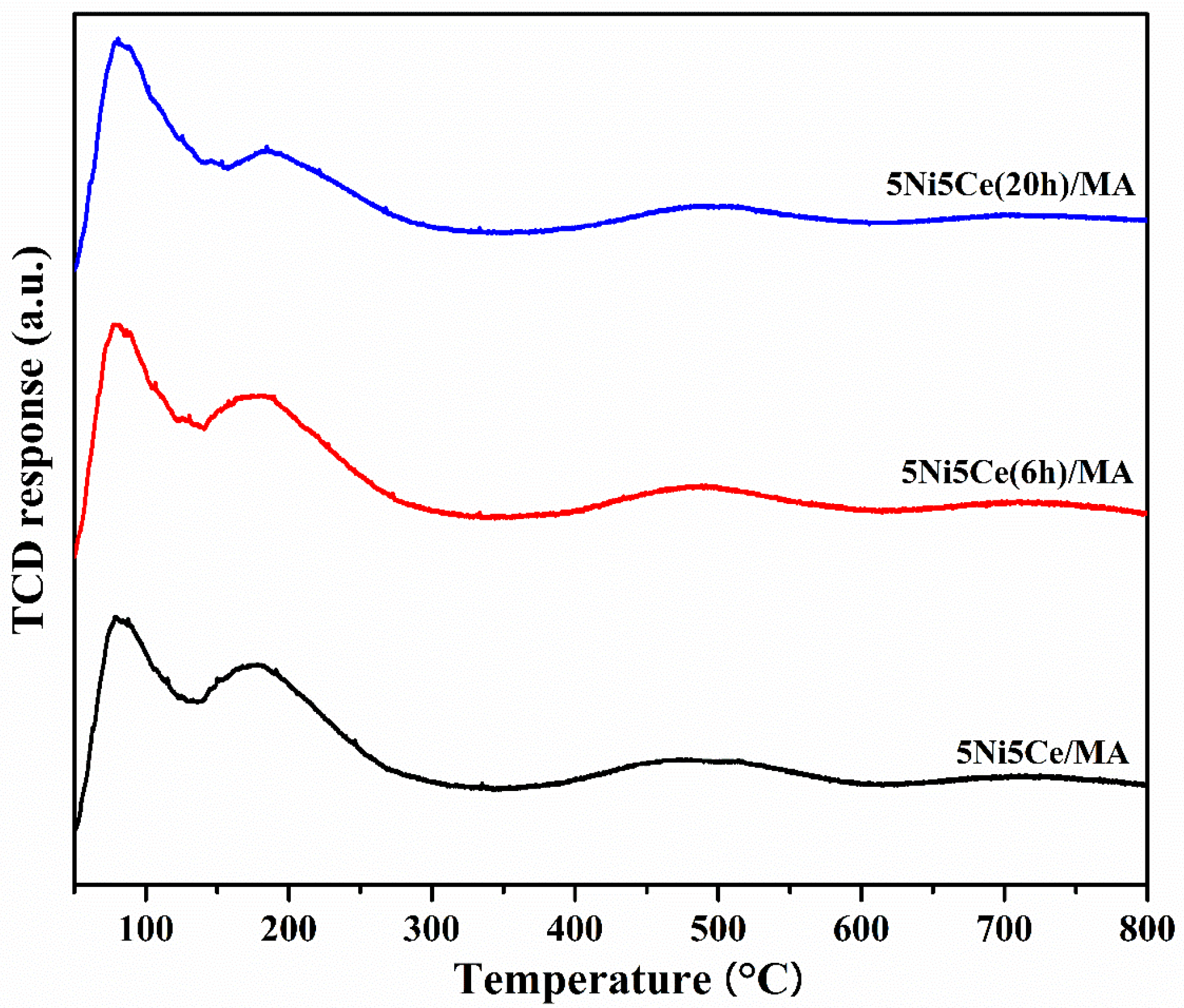
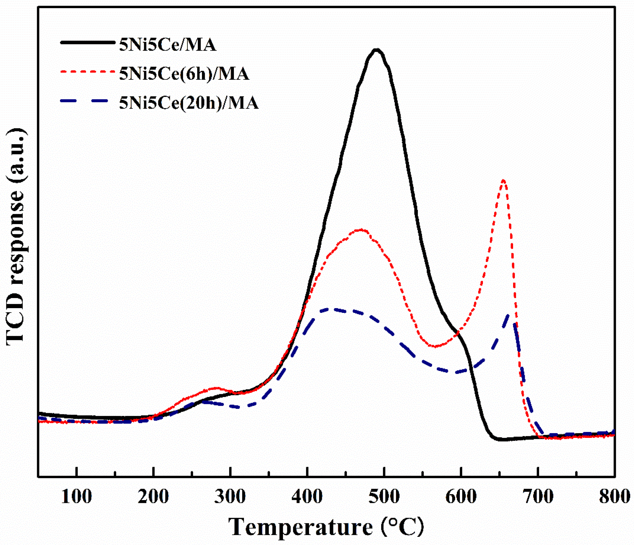
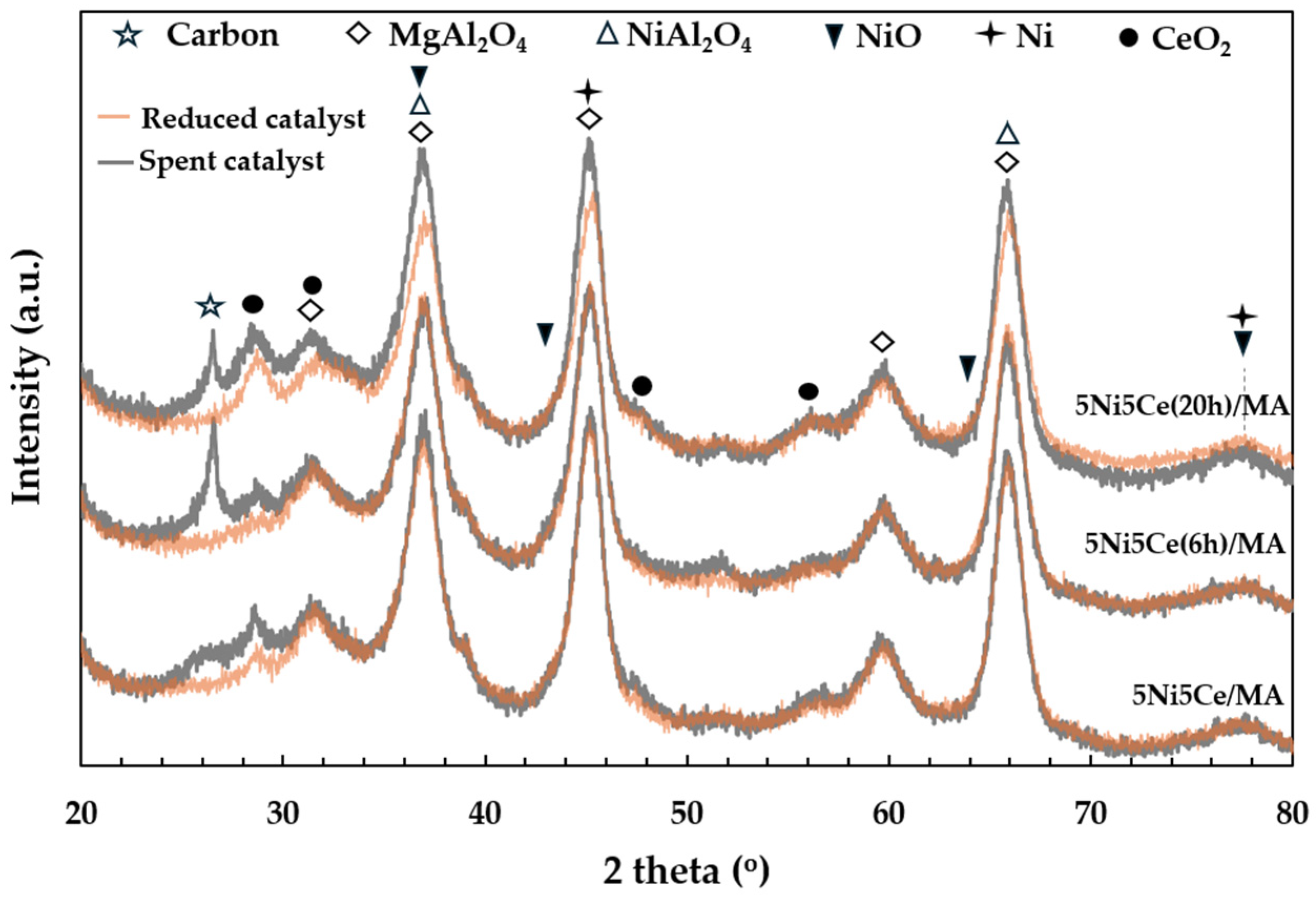
The carbon deposition on each spent catalyst after the CRM test was analyzed by TPO measurement (Figure 11), FESEM (Figure 12), and XRD (Figure 13). The oxygen consumption curves representing the carbon oxidation profiles of all samples are depicted in Figure 10, and the amount of oxygen consumptions are reported in Table 6. The oxidation peaks in the low-to-medium-temperature (<500 °C) and high-temperature (>500 °C) ranges can be assigned to the combustion of amorphous carbon and graphitic carbon collaborating with filamentous carbon, respectively [16,66,67,68,69,70]. The greatest amount of total oxygen consumption found on the spent 5Ni5Ce/MA suggests the largest amount of coke deposition. It decreased by 30% on the spent 5Ni5Ce(6 h)/MA and decreased by half on the spent 5Ni5Ce(20 h)/MA. Although a large amount of filamentous carbon was spread out over the surface of 5Ni5Ce/MA (Figure 12a–c), this carbon filament on the spent 5Ni5Ce/MA was oxidized easier than the treated catalysts due to the lower oxidation temperature. The XRD diffractograms of the reduced and spent catalysts establish the phase maintained during the reaction with the deposition of graphitic carbon (Figure 13). The XRD diffractograms of the spent catalysts display the peak patterns of graphitic carbon (JCPDS No. 41-1487) only on the treated catalysts [16,71]. This evidence reflects the change in the electronic effect on the nickel–ceria catalyst caused by the ammonia diffusion impregnation method. The electronic interaction of NiO-CeO2 developed through LDH synthesis generates and grows surface hydroxyl with the oxygen transfer pathway of the Ni-NiO-CeO2 network. However, it decreases the oxygen vacancies of CeO2 compared to the reduced 5Ni5Ce/MA catalyst. As a consequent, the reactant cracking, especially CO2, on 5Ni5Ce/MA is slower by the metal–oxide pair basic sites and the coke oxidation is driven only by surface oxygen (O*) from the CO2 adsorption–dissociation. Moreover, the beneficial pathway of oxygen transfer through the Ni-NiO-CeO2 network to the deposited carbon rarely takes place on this catalyst. When the 5Ni5Ce/MA catalyst is treated in the ammonia vapor, the reactant cracking becomes faster and more specific onto the appropriate sites as explained above. Thus, graphitic carbon and a thick carbon filament were found on the treated catalysts. The smaller amount of coke deposited on the treated catalysts represents the higher rate of coke removal. This is attributed to the implementation of oxygen transfer into the Ni-NiO-CeO2 network associated with the rehydration property of Ni-NiO-CeO2 interactions, indicating more surface hydroxyl (OH)*. Ni-NiO-CeO2 nanoparticles on 5Ni5Ce(20 h)/MA provide OH* and O* to drive the reaction pathways that transform CH* and C* to CO* (Equations (5)–(7)).
CH* + O* → CHO* + *→ CO* + H*
C* + O* → CO* + *
C* + OH* → CHO* + *→ CO* + H*
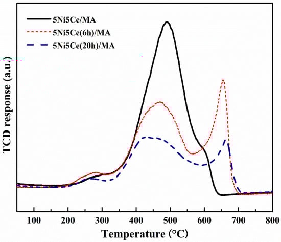
Figure 11.
TPO profile of spent catalysts after CRM reaction.
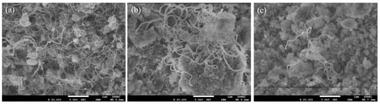
Figure 12.
FESEM micrographs of spent (a) 5Ni5Ce/MA, (b) 5Ni5Ce(6 h)/MA, and (c) 5Ni5Ce(20 h)/MA catalysts.
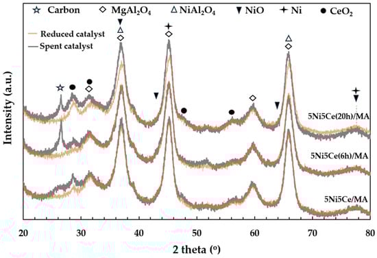
Figure 13.
The X-ray diffraction patterns of the reduced catalysts and spent catalysts.
Table 6.
The O2 consumption for carbon oxidation on all spent catalysts.
3. Materials and Methods
3.1. Material Preparation
The catalyst support, 10 wt% MgO/Al2O3 (MA), was synthesized by incipient wetness impregnation of Al2O3 powder (98%, Sigma Aldrich, St. Louis, MO, USA) with an aqueous solution of Mg(NO3)2·6H2O (98%, Acros Organics, Waltham, MA, USA). The wet powder was stabilized in ambient condition for 12 h before being dried at 50 °C overnight and calcined at 650 °C for 6 h. Afterwards, 5 wt% Ni-5 wt% CeO2/MgO-Al2O3 (5Ni5Ce/MA) was prepared through the conventional co-impregnation method. The mixture of the required portion of the Ni(NO3)2·6H2O (98%, Acros Organics) solution and the Ce(NO3)3·6H2O (98%, Sigma Aldrich) solution was dropped onto the MA support followed by drying at 50 °C overnight and calcination at 650 °C for 6 h.
To generate two treated catalysts with various interactions on the surface, the 5Ni5Ce(xh)/MA (xh = 6 h and 20 h) catalysts were synthesized using an ammonia vapor diffusion impregnation method outlined in our previous work [19]. The wet solid cake of the impregnated 5Ni5Ce/MA catalyst was kept under ammonia vapor diffusion conditions at ambient temperature in a closed chamber for 6 h (5Ni5Ce(6 h)/MA) and for 20 h (5Ni5Ce(20 h)/MA). During the ammonia diffusion, a limited amount of hydroxide ions was intercalated with the nitrate ions of the Ni2+ and Ce3+ solutions, resulting in the slow growth of the layered double hydroxide nanosheet structure. Hence, the size and dispersion of the layered double hydroxide nanosheets were controlled by diffusion time. The resulting wet powder was dried and calcined using similar conditions to those used for the 5Ni5Ce/MA catalyst. All catalysts were pelletized, ground, and sieved to a particle size range between 355 and 710 μm.
3.2. Material Characterization
The surface morphologies of the calcined and spent catalysts were characterized by field emission scanning electron microscopy (FESEM) using the JEOL instrument model JSM-7610F (JEOL Ltd., Welwyn Garden City, UK) with an accelerating voltage of 1.00 kV. Prior to the analyzation, each catalyst sample was prepared by sputter coating with platinum (Pt) using a QUORUM Q150R S (Quorum, East Sussex, UK) apparatus.
The surface area and pore properties of the catalyst were obtained using the N2 adsorption–desorption isotherm measured at −196 °C on an Autosorb iQ Station 2 (Quantachrome Instruments, Boynton Beach, FL, USA). Prior to the experiment, the catalyst was outgassed at 350 °C under a N2 flow for 3 h. The surface area and the total pore volume were analyzed by multipoint Brunauer–Emmett–Teller (BET) method. The average pore diameter was calculated from the Barett–Joyner–Halenda (BJH) method.
The crystalline phase compositions of the prepared support, calcined catalysts, reduced catalysts, and spent catalysts were identified by X-ray diffraction (XRD, Bruker AXS Model D8 Discover, Billerica, MA, USA) with CuKα radiation at 40 kV and 40 mA and recorded in 2 theta ranges of 10–80° with the step size of 0.02° min−1. The average crystallite sizes (DXRD) on the fresh catalysts were calculated from the values of full width at half maximum (FWHM) of the intense diffraction peak at 2 theta = 28° for CeO2 using Scherrer’s equation (Equation (8)), where K is the particle shape factor (0.94), λ is 1.5418 Å, β is line broadening in radians, and θ is the Bragg angle.
The reducibility of the calcined catalysts was analyzed by hydrogen temperature-programmed reduction (H2-TPR) measurements performed on a BELCAT basic system (BEL JAPAN, INC., Osaka, Japan) using a thermal conductivity detector (TCD). A total of 0.050 g of each sample was first degassed with Ar flow at 220 °C for 1.5 h, and cooled down to 40 °C. In the measurement, the sample was reduced in the reducing gas flow (5 vol% H2/Ar, 30 mL min−1) from 50 °C to 800 °C with a ramping rate of 10 °C min−1. The water vapor from the gas stream was removed using a molecular sieve 4A, and the hydrogen consumption was examined by the TCD equipped in the analyzer.
The chemical states of Ni and Ce in the reduced catalysts were investigated by X-ray photoelectron spectroscopy (XPS) measurement, employing a PHI5000 Versa Probe II (ULVAC-PHI, Chigasaki, Japan). Prior to the measurement, catalysts were reduced ex situ at 600 °C for 3 h under pure H2. The monochromatic AlKα X-ray (1486.6 eV) was utilized as an excitation source. The C 1s BE at 285.0 eV was used as a reference for calibration. The high-resolution XPS spectra were collected with an energy step of 0.1 eV and pass energy of 46.95 eV. After measurement, XPS spectra were analyzed using the CasaXPS software (version 2.3.26).
The dispersion of metal active sites was investigated via H2 temperature-programmed desorption (H2-TPD) measured on the BELCAT basic system. Firstly, the catalyst sample (0.050 g) was pre-treated in Ar flow (30 mL min−1) at 220 °C for 1 h, reduced in situ with pure H2 flow (30 mL min−1) at 600 °C for 1.5 h, and cooled to 120 °C in Ar flow. After that, the H2 adsorption on the reduced catalyst was carried out in pure H2 flow at 120 °C for 1h. The physiosorbed H2 was purged with Ar flow for 1 h, and the sample was cooled to 50 °C. Finally, the H2-TPD measurement was performed from 50 °C to 850 °C at the heating rate of 10 °C min−1 in Ar flow.
The surface alkalinity and basic strength distribution of the reduced catalysts were evaluated by CO2 temperature-programmed desorption (CO2-TPD) conducted on the same BELCAT apparatus. Prior to the experiment, the catalyst sample was pre-treated in He flow (30 mL min−1) at 220 °C for 1 h, and reduced in situ with pure H2 flow (30 mL min−1) at 600 °C for 1.5 h. The sample was thereafter cooled to 40 °C in He flow, and an isothermal CO2 adsorption was subsequently introduced to the catalyst surface at 40 °C for 1 h. The unadsorbed CO2 was removed by flushing with He flow for 1 h. Then, the CO2 desorption was measured with a heating rate of 10 °C min−1 to 800 °C in He flow.
The total amount of oxygen mobility and the distribution of the mobile species were determined via temperature-programmed desorption of oxygen (O2-TPD) on the same BELCAT instrument (Microtrac, York, PA, USA). Before the O2 adsorption step, the catalyst sample was pre-treated and pre-reduced in situ under the same conditions as H2-TPD. The sample was cooled to 200 °C in Ar flow. Afterward, O2 adsorption on the reduced catalyst was carried out in pure O2 flow at 200 °C for 1.5 h and the physiosorbed O2 was removed with Ar flow. Then, the desorption was monitored from 50 °C to 800 °C at a heating rate of 10 °C min−1 in Ar flow.
The total carbon deposition and carbon type distribution on the spent catalysts after the CRM reaction test were elucidated by temperature-programmed oxidation (TPO) using the BELCAT basic system. A total of 0.050 g of each spent catalyst was cleaned in Ar flow (30 mL min−1) at 220 °C for 2 h, followed by cooling to 40 °C before the TPO measurement. Then, the cleaned sample was oxidized in a 5 vol.% O2/Ar flow (30 mL min−1) with a ramping rate of 10 °C min−1 from 50 °C to 800 °C. The CO2 product that evolved from the catalyst surface was removed by a 4A molecular sieve and the oxygen consumption was determined by the TCD equipped in the analyzer.
3.3. Catalytic Performance Tests
The CRM was tested in a tubular reactor at 600 °C under atmospheric pressure for 16 h. Prior to each test, a 350 mg catalyst sample was reduced in situ under H2 flow (30 mL min−1) at 600 °C for 3 h. Then, the reaction feedstock of a CH4:CO2:N2 mixture with a molar ratio of 3:5:4 at the total flow rate of 60 mL min−1 was introduced into the reactor. The composition of the outlet stream was analyzed using an on-line gas chromatograph (Agilent GC7890A, Santa Clara, CA, USA) equipped with a TCD. The reactant conversions (Equations (9) and (10)), product yields (Equations (11) and (12)), and H2/CO ratio (Equation (13)) were calculated by the equations below.
4. Conclusions
This study discloses the effect of the growth of Ni-NiO-CeO2 nanoparticles on 5 wt% Ni-5 wt% CeO2/MA (treated) catalyst employing impregnation-assisted ammonia vapor diffusion for 6 h and 20 h. Compared to the untreated 5 wt%Ni-5 wt%CeO2/MA, the growth of Ni-NiO-CeO2 nanoparticles constructed a Ni-NiO-CeO2 network on the MA support with electronic interaction. The short duration of ammonia vapor diffusion initiates the electronic interaction of Ni-NiO-CeO2, interrupts strong metal–support interaction, creates a high dispersion of small Ni-NiO-CeO2 nanoparticles, and increases surface hydroxyl basic sites. A stronger interaction in the Ni-NiO-CeO2 network is developed over the ammonia diffusion time. Ni metal and the surface hydroxyl sites on Ni-NiO-CeO2 nanostructures with lower metal–support interaction raise catalytic activities toward involving a drastic reactant dissociation. Although the hard removal types of coke are formed on treated catalysts, the rate of coke oxidation is dramatically driven by mobile O* and OH* in strong Ni-NiO-CeO2 interactions.
Author Contributions
Conceptualization, M.P. and S.T.; methodology, M.P., S.T., S.I., and W.S.; validation, M.P., S.T. and S.I.; formal analysis, M.P., S.T., S.I., W.S., and T.R.; investigation, M.P.; resources, M.P.; data curation, M.P. and S.T.; writing—original draft preparation, M.P., S.T., and S.I.; writing—review and editing, M.P. and S.T.; visualization, M.P.; supervision, M.P.; project administration, M.P.; funding acquisition, M.P. All authors have read and agreed to the published version of the manuscript.
Funding
This research was funded by the National Science, Research, and Innovation Fund (NSRF) and King Mongkut’s University of Technology North Bangkok with Contract no. KMUTNB-FF-66-25.
Institutional Review Board Statement
Not applicable.
Informed Consent Statement
Not applicable.
Data Availability Statement
Data are contained within the article.
Acknowledgments
This work was supported by the National Science, Research, and Innovation Fund (NSRF) and King Mongkut’s University of Technology North Bangkok under research grant number KMUTNB-FF-66-25. The XPS measurements were performed at the SUT-NANOTEC-SLRI joint research facility of the Synchrotron Light Research Institute (SLRI), Thailand.
Conflicts of Interest
The authors declare no potential conflicts of interest with respect to the research, authorship, and/or publication of this article.
References
- Li, R.; Gao, T.; Wang, Y.; Chen, Y.; Luo, W.; Wu, Y.; Zhang, Y. Engineering of bimetallic Au–Pd alloyed particles on nitrogen defects riched g-C3N4 for efficient photocatalytic hydrogen production. Int. J. Hydrogen Energy 2024, 63, 1116–1127. [Google Scholar] [CrossRef]
- Cao, Y.; Fang, H.; Guo, C.; Sun, W.; Xu, Y.; Wu, Y.; Wang, Y. Alkynyl boosted high-performance lithium storage and mechanism in covalent phenanthroline framework. Angew. Chem. Int. Ed. 2023, 62, e202302143. [Google Scholar] [CrossRef]
- Arora, S.; Prasad, R. An overview on dry reforming of methane: Strategies to reduce carbonaceous deactivation of catalysts. RSC Adv. 2016, 6, 108668–108688. [Google Scholar] [CrossRef]
- Zhang, X.; Zhang, Q.; Tsubaki, N.; Tan, Y.; Han, Y. Carbon dioxide reforming of methane over Ni nanoparticles incorporated into mesoporous amorphous ZrO2 matrix. Fuel 2015, 147, 243–252. [Google Scholar] [CrossRef]
- Zhang, X.; Wang, F.; Song, Z.; Zhang, S. Comparison of carbon deposition features between Ni/ZrO2 and Ni/SBA-15 for the dry reforming of methane Reaction Kinetics. Mech. Catal. 2020, 129, 457–470. [Google Scholar]
- Ye, R.P.; Gong, W.; Sun, Z.; Sheng, Q.; Shi, X.; Wang, T.; Yao, Y.G. Enhanced stability of Ni/SiO2 catalyst for CO2 methanation: Derived from nickel phyllosilicate with strong metal-support interactions. Energy 2019, 188, 116059. [Google Scholar] [CrossRef]
- Yan, X.U.; Du, X.H.; Jing, L.I.; Peng, W.A.; Jie, Z.H.; Ge, F.J.; Jun, Z.H.; Ming, S.O.; Zhu, W.Y. A comparison of Al2O3 and SiO2 supported Ni-based catalysts in their performance for the dry reforming of methane. J. Fuel Chem. Technol. 2019, 47, 199–208. [Google Scholar]
- Arman, A.; Hagos, F.Y.; Abdullah, A.A.; Mamat, R.; Aziz, A.R.A.; Cheng, C.K. Syngas production through steam and CO2 reforming of methane over Ni-based catalyst-A Review. IOP Conf. Ser. Mater. Sci. Eng. 2020, 736, 042032. [Google Scholar] [CrossRef]
- Wei, M.; Shi, X. Research Progress on Stability Control on Ni-Based Catalysts for Methane Dry Reforming. Methane 2024, 3, 86–102. [Google Scholar] [CrossRef]
- Mohanty, U.S.; Ali, M.; Azhar, M.R.; Al-Yaseri, A.; Keshavarz, A.; Iglauer, S. Current advances in syngas (CO + H2) production through bi-reforming of methane using various catalysts: A review. Int. J. Hydrogen Energy 2021, 46, 32809–32845. [Google Scholar] [CrossRef]
- Deng, H.; Guo, Y. Artificial Neural Network Model for the Prediction of Methane Bi-Reforming Products Using CO2 and Steam. Processes 2022, 10, 1052. [Google Scholar] [CrossRef]
- Kim, M.J.; Youn, J.R.; Kim, H.J.; Seo, M.W.; Lee, D.; Go, K.S.; Jeon, S.G. Effect of surface properties controlled by Ce addition on CO2 methanation over Ni/Ce/Al2O3 catalyst. Int. J. Hydrogen Energy 2020, 45, 24595–24603. [Google Scholar] [CrossRef]
- Rad, S.J.H.; Haghighi, M.; Eslami, A.A.; Rahmani, F.; Rahemi, N. Sol–gel vs. impregnation preparation of MgO and CeO2 doped Ni/Al2O3 nanocatalysts used in dry reforming of methane: Effect of process conditions, synthesis method and support composition. Int. J. Hydrogen Energy 2016, 41, 5335–5350. [Google Scholar]
- Moogi, S.; Lee, I.G.; Hwang, K.R. Catalytic steam reforming of glycerol over Ni–La2O3–CeO2/SBA-15 catalyst for stable hydrogen-rich gas production. Int. J. Hydrogen Energy 2020, 45, 28462–28475. [Google Scholar] [CrossRef]
- Aghamohammadi, S.; Haghighi, M.; Maleki, M.; Rahemi, N. Sequential impregnation vs. sol-gel synthesized Ni/Al2O3-CeO2 nanocatalyst for dry reforming of methane: Effect of synthesis method and support promotion. Mol. Catal. 2017, 431, 39–48. [Google Scholar] [CrossRef]
- Luisetto, I.; Tuti, S.; Battocchio, C.; Lo Mastro, S.; Sodo, A. Ni/CeO2-Al2O3 catalysts for the dry reforming of methane: The effect of CeAlO3 content and nickel crystallite size on catalytic activity and coke resistance. Appl. Catal. A Gen. 2015, 500, 12–22. [Google Scholar] [CrossRef]
- Ismail, A.; Zahid, M.; Hu, B.; Khan, A.; Ali, N.; Zhu, Y. Effect of Morphology-Dependent Oxygen Vacancies of CeO2 on the Catalytic Oxidation of Toluene. Catalysts 2022, 12, 1034. [Google Scholar] [CrossRef]
- Damyanova, S.; Pawelec, B.; Palcheva, R.; Karakirova, Y.; Sanchez, M.C.; Tyuliev, G.; Fierro, J.L.G. Structure and surface properties of ceria-modified Ni-based catalysts for hydrogen production. Appl. Catal. B Environ. 2018, 225, 340–353. [Google Scholar] [CrossRef]
- Dharmasaroja, N.; Ratana, T.; Tungkamani, S.; Sornchamni, T.; Simakov, D.S.A.; Phongaksorn, M. CO2 reforming of methane over the growth of hierarchical Ni nanosheets/Al2O3-MgO synthesized via the ammonia vapour diffusion impregnation. Can. J. Chem. Eng. 2020, 99, S585–S595. [Google Scholar] [CrossRef]
- Sumarasingha, W.; Tungkamani, S.; Ratana, T.; Supasitmongkol, S.; Phongaksorn, M. Combined Steam and CO2 Reforming of Methane over the Hierarchical Ni-ZrO2 Nanosheets/Al2O3 Catalysts at Ultralow Temperature and under Low Steam. ACS Omega 2023, 8, 46425–46437. [Google Scholar] [CrossRef]
- Ratana, T.; Jadsadajerm, S.; Tungkamani, S.; Sumarasingha, W.; Phongaksorn, M. Effect of modified surface of Co/Al2O3 on properties and catalytic performance for CO2 reforming of methane. J. Phys. Chem. Solids 2024, 191, 112034. [Google Scholar] [CrossRef]
- Díez, D.; Urueña, A.; Antolín, G. Investigation of Ni–Fe–Cu-layered double hydroxide catalysts in steam reforming of toluene as a model compound of biomass tar. Processes 2020, 9, 76. [Google Scholar] [CrossRef]
- Matusik, J. Layered double hydroxides (LDH) and LDH-based hybrid composites. Materials 2021, 14, 2582. [Google Scholar] [CrossRef]
- Michalik, A.; Napruszewska, B.D.; Walczyk, A.; Kryściak-Czerwenka, J.; Duraczyńska, D.; Serwicka, E.M. Synthesis of nanocrystalline Mg-Al hydrotalcites in the presence of starch—The effect on structure and composition. Materials 2020, 13, 602. [Google Scholar] [CrossRef] [PubMed]
- Amin, M.H. Relationship between the pore structure of mesoporous silica supports and the activity of nickel nanocatalysts in the CO2 reforming of methane. Catalysts 2020, 10, 51. [Google Scholar] [CrossRef]
- Li, M.; Cheng, J.P.; Wang, J.; Liu, F.; Zhang, X.B. The growth of nickel-manganese and cobalt-manganese layered double hydroxides on reduced graphene oxide for supercapacitor. Electrochim. Acta 2016, 206, 108–115. [Google Scholar] [CrossRef]
- Dębek, R.; Zubek, K.; Motak, M.; Galvez, M.E.; Da Costa, P.; Grzybek, T. Ni-Al hydrotalcite-like material as the catalyst precursors for the dry reforming of methane at low temperature. Comptes Rendus Chim. 2015, 18, 1205–1210. [Google Scholar] [CrossRef]
- Wang, Z.; Jiang, X.; Pan, M.; Shi, Y. Nano-scale pore structure and its multi-fractal characteristics of tight sandstone by N2 adsorption/desorption analyses: A case study of shihezi formation from the sulige gas filed, ordos basin, china. Minerals 2020, 10, 377. [Google Scholar] [CrossRef]
- Das, S.; Sengupta, M.; Patel, J.; Bordoloi, A. A study of the synergy between support surface properties and catalyst deactivation for CO2 reforming over supported Ni nanoparticles. Appl. Catal. A Gen. 2017, 545, 113–126. [Google Scholar] [CrossRef]
- Farooqi, A.S.; Yusuf, M.; Zabidi, N.A.M.; Saidur, R.; Sanaullah, K.; Farooqi, A.S.; Abdullah, B. A comprehensive review on improving the production of rich-hydrogen via combined steam and CO2 reforming of methane over Ni-based catalysts. Int. J. Hydrogen Energy 2021, 46, 31024–31040. [Google Scholar] [CrossRef]
- Abd Ghani, N.A.; Azapour, A.; Syed Muhammad, S.A.F.; Mohamed Ramli, N.; Vo, D.V.N.; Abdullah, B. Dry reforming of methane for syngas production over Ni–Co–supported Al2O3–MgO catalysts. Appl. Petrochem. Res 2018, 8, 263–270. [Google Scholar] [CrossRef]
- Ha, Q.L.M.; Armbruster, U.; Atia, H.; Schneider, M.; Lund, H.; Agostini, G.; Martin, A. Development of active and stable low nickel content catalysts for dry reforming of methane. Catalysts 2017, 7, 157. [Google Scholar] [CrossRef]
- High, M.; Patzschke, C.F.; Zheng, L.; Zeng, D.; Gavalda-Diaz, O.; Ding, N.; Song, Q. Precursor engineering of hydrotalcite-derived redox sorbents for reversible and stable thermochemical oxygen storage. Nat. Commun. 2022, 13, 5109. [Google Scholar] [CrossRef] [PubMed]
- Dębek, R.; Motak, M.; Galvez, M.E.; Grzybek, T.; Da Costa, P. Promotion effect of zirconia on Mg(Ni,Al)O mixed oxides derived from hydrotalcites in CO2 methane reforming. Appl. Catal. B Environ. 2018, 223, 36–46. [Google Scholar] [CrossRef]
- Wang, F.; Yang, X.; Zhang, J. Well-dispersed MgAl2O4 supported Ni catalyst with enhanced catalytic performance and the reason of its deactivation for long-term dry methanation reaction. Catalysts 2021, 11, 1117. [Google Scholar] [CrossRef]
- Kannan, P.; Maiyalagan, T.; Marsili, E.; Ghosh, S.; Niedziolka-Jönsson, J.; Jönsson-Niedziolka, M. Hierarchical 3-dimensional nickel–iron nanosheet arrays on carbon fiber paper as a novel electrode for non-enzymatic glucose sensing. Nanoscale 2016, 8, 843–855. [Google Scholar] [CrossRef]
- Shin, S.A.; Alizadeh Eslami, A.; Noh, Y.S.; Song, H.T.; Kim, H.D.; Ghaffari Saeidabad, N.; Moon, D.J. Preparation and Characterization of Ni/ZrTiAlOx Catalyst via Sol-Gel and Impregnation Methods for Low Temperature Dry Reforming of Methane. Catalysts 2020, 10, 1335. [Google Scholar] [CrossRef]
- Al-Doghachi, F.A.J.; Islam, A.; Zainal, Z.; Saiman, M.I.; Embong, Z.; Taufiq-Yap, Y.H. High coke-resistance Pt/Mg1-xNixO catalyst for dry reforming of methane. PLoS ONE 2016, 11, e0145862. [Google Scholar] [CrossRef] [PubMed]
- Mastuli, M.S.; Kasim, M.F.; Mahat, A.M.; Asikin-Mijan, N.; Sivasangar, S.; Taufiq-Yap, Y.H. Structural and catalytic studies of Mg1-xNixO nanomaterials for gasification of biomass in supercritical water for H2-rich syngas production. Int. J. Hydrogen Energy 2020, 45, 33218–33234. [Google Scholar] [CrossRef]
- Siang, T.J.; Pham, T.L.; Van Cuong, N.; Phuong, P.T.; Phuc, N.H.H.; Truong, Q.D.; Vo, D.V.N. Combined steam and CO2 reforming of methane for syngas production over carbon-resistant boron-promoted Ni/SBA-15 catalysts. Microporous Mesoporous Mater. 2018, 262, 122–132. [Google Scholar] [CrossRef]
- Millet, M.M.; Tarasov, A.V.; Girgsdies, F.; Algara-Siller, G.; Schlögl, R.; Frei, E. Highly Dispersed Ni0/NixMg1-xO Catalysts Derived from Solid Solutions: How Metal and Support Control the CO2 Hydrogenation. ACS Catal. 2019, 9, 8534–8546. [Google Scholar] [CrossRef]
- Karuppiah, J.; Reddy, E.L.; Mok, Y.S. Anodized aluminum oxide supported NiO-CeO2 catalyst for dry reforming of propane. Catalysts 2016, 6, 154. [Google Scholar] [CrossRef]
- Loc, L.C.; Phuong, P.H.; Tri, N. Role of CeO2 promoter in NiO/α-Al2O3 catalyst for dry reforming of methane. Proceeding Name AIP Conf. 2017, 1878, 020033. [Google Scholar]
- Cárdenas-Arenas, A.; Bailón-García, E.; Lozano-Castelló, D.; Da Costa, P.; Bueno-López, A. Stable NiO–CeO2 nanoparticles with improved carbon resistance for methane dry reforming. J. Rare Earths 2022, 40, 57–62. [Google Scholar] [CrossRef]
- Yahi, N.; Menad, S.; Rodríguez-Ramos, I. Dry reforming of methane over Ni/CeO2 catalysts prepared by three different methods. Green Process. Synth. 2015, 4, 479–486. [Google Scholar] [CrossRef]
- Rui, N.; Zhang, X.; Zhang, F.; Liu, Z.; Cao, X.; Xie, Z.; Liu, C.J. Highly active Ni/CeO2 catalyst for CO2 methanation: Preparation and characterization. Appl. Catal. B Environ. 2021, 282, 119581. [Google Scholar] [CrossRef]
- Marinho, A.L.A.; Toniolo, F.S.; Noronha, F.B.; Epron, F.; Duprez, D.; Bion, N. Highly active and stable Ni dispersed on mesoporous CeO2-Al2O3 catalysts for production of syngas by dry reforming of methane. Appl. Catal. B Environ. 2021, 281, 119459. [Google Scholar] [CrossRef]
- Singha, R.K.; Shukla, A.; Yadav, A.; Adak, S.; Iqbal, Z.; Siddiqui, N.; Bal, R. Energy efficient methane tri-reforming for synthesis gas production over highly coke resistant nanocrystalline Ni–ZrO2 catalyst. Appl. Energy 2016, 178, 110–125. [Google Scholar] [CrossRef]
- Greluk, M.; Rotko, M.; Słowik, G.; Turczyniak-Surdacka, S.; Grzybek, G.; Góra-Marek, K.; Kotarba, A. Effect of potassium pro-moter on the performance of cobalt catalysts on steam reforming of ethanol. Catalysts 2022, 11, 600. [Google Scholar] [CrossRef]
- Okhlopkova, L.; Prosvirin, I.; Kerzhentsev, M.; Ismagilov, Z. Combined Steam and CO2 Reforming of Methane over Ni-Based CeO2-MgO Catalysts: Impacts of Preparation Mode and Pd Addition. Appl. Sci. 2023, 13, 4689. [Google Scholar] [CrossRef]
- Vacharapong, P.; Arayawate, S.; Katanyutanon, S.; Toochinda, P.; Lawtrakul, L.; Charojrochkul, S. Enhancement of Ni catalyst using CeO2–Al2O3 support prepared with magnetic inducement for ESR. Catalysts 2020, 10, 1357. [Google Scholar] [CrossRef]
- Tapia-P, J.; Gallego, J.; Espinal, J.F. Calcination Temperature Effect in Catalyst Reactivity for the CO SELOX Reaction Using Perovskite-like LaBO3 (B: Mn, Fe, Co, Ni) Oxides. Catal. Lett. 2021, 151, 3690–3703. [Google Scholar] [CrossRef]
- Zeng, Q.; Xie, W.; Chen, Z.; Wang, X.; Akinoglu, E.M.; Zhou, G.; Shui, L. Influence of the facets of Bi24O31Br10 nanobelts and nanosheets on their photocatalytic properties. Catalysts 2020, 10, 257. [Google Scholar] [CrossRef]
- Li, M.; Wang, X.; Cárdenas-Lizana, F.; Keane, M.A. Effect of support redox character on catalytic performance in the gas phase hydrogenation of benzaldehyde and nitrobenzene over supported gold. Catal. Today 2017, 279, 19–28. [Google Scholar] [CrossRef]
- Ebiad, M.A.; Abd El-Hafiz, D.R.; Elsalamony, R.A.; Mohamed, L.S. Ni supported high surface area CeO2-ZrO2 catalysts for hydrogen production from ethanol steam reforming. RSC Adv. 2012, 2, 8145–8156. [Google Scholar] [CrossRef]
- Li, L.; Wang, Y.; Zhao, Q.; Hu, C. The effect of Si on CO2 methanation over Ni-xSi/ZrO catalysts at low temperature. Catalysts 2021, 11, 67. [Google Scholar] [CrossRef]
- Sikander, U.; Sufian, S.; Salam, M.A. A review of hydrotalcite based catalysts for hydrogen production systems. Int. J. Hydrogen Energy 2017, 42, 19851–19868. [Google Scholar] [CrossRef]
- Phuong, P.H.; Loc, L.C.; Tri, N.; Anh, N.P.; Anh, H.C. Effect of NH3 Alkalization and MgO Promotion on the Performance of Ni/SBA-15 Catalyst in Combined Steam and Carbon Dioxide Reforming of Methane. J. Nanomater. 2021, 2021, 5570866. [Google Scholar] [CrossRef]
- Dan, M.; Mihet, M.; Borodi, G.; Lazar, M.D. Combined steam and dry reforming of methane for syngas production from biogas using bimodal pore catalysts. Catal. Today 2020, 366, 87–96. [Google Scholar]
- Radlik, M.; Adamowska-Teyssier, M.; Krztoń, A.; Kozieł, K.; Krajewski, W.; Turek, W.; Da Costa, P. Dry reforming of methane over Ni/Ce0.62Zr0.38O2 catalysts: Effect of Ni loading on the catalytic activity and on H2/CO production. Comptes Rendus Chim. 2015, 8, 1242–1249. [Google Scholar] [CrossRef]
- Huang, H.; Zhang, X.; Liu, J.; Ye, S. Study on oxidation activity of Ce–Mn–K composite oxides on diesel soot. Sci. Rep. 2020, 10, 10025. [Google Scholar] [CrossRef]
- Wang, K.; Liu, X.; Tu, S.; Zhang, L.; Jiang, C.; Li, W.; Ye, D. Catalytic Oxidation of Toluene over Manganese and Cerium Complex Oxide Supported on Zeolite. J. Phys. Conf. Ser. 2020, 1676, 012064. [Google Scholar] [CrossRef]
- Weng, X.; Shi, B.; Liu, A.; Sun, J.; Xiong, Y.; Wan, H.; Chen, Y.W. Highly dispersed Pd/modified-Al2O3 catalyst on complete oxidation of toluene: Role of basic sites and mechanism insight. Appl. Surf. Sci. 2019, 497, 143747. [Google Scholar] [CrossRef]
- Siang, T.J.; Danh, H.T.; Singh, S.; Truong, Q.D.; Setiabudi, H.D.; Vo, D.V.N. Syngas production from combined steam and carbon dioxide reforming of methane over Ce-modified silica supported nickel catalysts. Chem. Eng. Trans. 2017, 56, 1129–1134. [Google Scholar]
- Sangsong, S.; Ratana, T.; Tungkamani, S.; Sornchamni, T.; Phongaksorn, M. Effect of CeO2 loading of the Ce-Al mixed oxide on ultrahigh temperature water-gas shift performance over Ce-Al mixed oxide supported Ni catalysts. Fuel 2019, 252, 488–495. [Google Scholar] [CrossRef]
- Koo, K.Y.; Lee, S.H.; Jung, U.H.; Roh, H.S.; Yoon, W.L. Syngas production via combined steam and carbon dioxide reforming of methane over Ni-Ce/MgAl2O4 catalysts with enhanced coke resistance. Fuel Process. Technol. 2014, 119, 151–157. [Google Scholar] [CrossRef]
- Abdulrasheed, A.; Jalil, A.A.; Gambo, Y.; Ibrahim, M.; Hambali, H.U.; Shahul Hamid, M.Y. A review on catalyst development for dry reforming of methane to syngas: Recent advances. Renew. Sustain. Energy Rev. 2019, 108, 175–193. [Google Scholar] [CrossRef]
- Zhao, Z.; Ren, P.; Li, W.; Miao, B. Effect of mineralizers for preparing ZrO2 support on the supported Ni catalyst for steam-CO2 bi-reforming of methane. Int. J. Hydrogen Energy 2017, 42, 6598–6609. [Google Scholar] [CrossRef]
- Chen, L.; Qi, Z.; Zhang, S.; Su, J.; Somorjai, G.A. Catalytic hydrogen production from methane: A review on recent progress and prospect. Catalysts 2020, 10, 858. [Google Scholar] [CrossRef]
- Nabgan, W.; Nabgan, B.; Abdullah, T.A.T.; Ngadi, N.; Jalil, A.A.; Hassan, N.S.; Majeed, F.S.A. Conversion of polyethylene terephthalate plastic waste and phenol steam reforming to hydrogen and valuable liquid fuel: Synthesis effect of Ni–Co/ZrO2 nanostructured catalysts. Int. J. Hydrogen Energy 2020, 45, 6302–6317. [Google Scholar] [CrossRef]
- Bang, S.; Hong, E.; Baek, S.W.; Shin, C.H. Effect of acidity on Ni catalysts supported on P-modified Al2O3 for dry reforming of methane. Catal. Today 2018, 303, 100–105. [Google Scholar] [CrossRef]

Disclaimer/Publisher’s Note: The statements, opinions and data contained in all publications are solely those of the individual author(s) and contributor(s) and not of MDPI and/or the editor(s). MDPI and/or the editor(s) disclaim responsibility for any injury to people or property resulting from any ideas, methods, instructions or products referred to in the content. |
© 2024 by the authors. Licensee MDPI, Basel, Switzerland. This article is an open access article distributed under the terms and conditions of the Creative Commons Attribution (CC BY) license (https://creativecommons.org/licenses/by/4.0/).