Article

Hydrochar from Pine Needles as a Green Alternative for Catalytic Electrodes in Energy Applications

by
Assunta Marrocchi
1,*,
Elisa Cerza
1,
Suhas Chandrasekaran
2,
Emanuela Sgreccia
2,
Saulius Kaciulis
3,
Luigi Vaccaro
1,
Suanto Syahputra
4,
Florence Vacandio
4,
Philippe Knauth
4 and
Maria Luisa Di Vona
2,*
1
Department of Chemistry, Biology and Biotechnology, University of Perugia, Via Elce di Sotto 8, 06123 Perugia, Italy
2
Tor Vergata University of Rome, Department Industrial Engineering and International Laboratory: Ionomer Materials for Energy (LIME), 00133 Roma, Italy
3
Institute for the Study of Nanostructured Materials, ISMN-CNR, Monterotondo Stazione, 00015 Roma, Italy
4
Aix Marseille University, CNRS, MADIREL (UMR 7246) and International Laboratory: Ionomer Materials for Energy (LIME), Campus St Jérôme, 13013 Marseille, France
*
Authors to whom correspondence should be addressed.
Molecules 2024, 29(14), 3286; https://doi.org/10.3390/molecules29143286
Submission received: 25 May 2024 / Revised: 9 July 2024 / Accepted: 10 July 2024 / Published: 11 July 2024

Abstract

:
Hydrothermal carbonization (HTC) serves as a sustainable method to transform pine needle waste into nitrogen-doped (N-doped) hydrochars. The primary focus is on evaluating these hydrochars as catalytic electrodes for the oxygen reduction reaction (ORR) and carbon dioxide reduction reaction (CO2RR), which are pivotal processes with significant environmental implications. Hydrochars were synthesized by varying the parameters such as nitrogen loading, temperature, and residence time. These materials were then thoroughly characterized using diverse analytical techniques, including elemental analysis, density measurements, BET surface area analysis, and spectroscopies like Raman, FTIR, and XPS, along with optical and scanning electron microscopies. The subsequent electrochemical assessment involved preparing electrocatalytic inks by combining hydrochars with an anion exchange ionomer (AEI) to leverage their synergistic effects. To the best of our knowledge, there are no previous reports on catalytic electrodes that simultaneously incorporate both a hydrochar and AEI. Evaluation metrics such as current densities, onset and half-wave potentials, and Koutecky–Levich and Tafel plots provided insights into their electrocatalytic performances. Notably, hydrochars synthesized at 230 °C exhibited an onset potential of 0.92 V vs. RHE, marking the highest reported value for a hydrochar. They also facilitated the exchange of four electrons at 0.26 V vs. RHE in the ORR. Additionally, the CO2RR yielded valuable C2 products like acetaldehyde and acetate. These findings highlight the remarkable electrocatalytic activity of the optimized hydrochars, which could be attributed, at least in part, to their optimal porosity.

Graphical Abstract

1. Introduction

The increasing interest in biomass-to-char conversion stems from a confluence of factors: economic incentives, sustainability imperatives, and a rising demand [1,2]. The transformation of lignocellulosic biomass waste into char is particularly appealing in addressing solid waste management, reducing raw material costs, and offering tailor-made properties for diverse applications. Bio-based char, with its carbon-rich composition, exhibits distinctive chemical, physical, and biological characteristics, depending on the carbonization technologies used in its production [3]. It is therefore an excellent candidate for various applications, including soil quality improvement, environmental remediation, enzyme immobilization, and sensing [4]. New materials derived from bio-based chars are also gaining attention for catalytic applications, as recently reviewed by Lyu et al. [5], Lee et al. [6], Xiong et al. [7], and Cao et al. [8] amongst others.
For most of the current renewable energies, even if well established, there is a need to mitigate the production costs and minimize the use of raw materials. In this context, bio-based char has demonstrated potential applications in renewable energy conversion and storage, as recently reported, particularly in microbial fuel cells, supercapacitors, and batteries (metal–ion and metal–air) [9,10,11]. In recent years, there has been notable interest in the utilization of hydrothermal carbonization (HTC) for converting biomass waste into valuable carbonaceous materials [12,13,14,15,16,17,18,19,20]. This method has garnered attention due to its capability to produce hydrochars (HCs) with desirable characteristics that enhance their efficient utilization across various applications, particularly in the materials domain [21,22,23,24]. Hydrothermal carbonization is an eco-friendly thermochemical conversion method utilizing subcritical water to convert wet or dry biomass into carbonaceous products by fractionating the feedstock. The carbonization temperature is moderate, typically in the range of 180–300 °C [17] and depends on the starting materials and their decomposition temperatures. This process effectively hydrolyzes and dehydrates biomass, resulting in hydrochars with a substantial content of oxygenated functional groups, contributing to a richer surface chemistry compared to pyrochars [3]. Moreover, HTC has the capability to leach inorganic elements into the liquid phase, reducing the ash content [25]. While significant advancements have been made, a hydrochar is a relatively new type of bio-based char compared to established options like pyrochars. This means that there is a smaller pool of existing research and a less complete understanding of its properties and applications, necessitating further research to unlock its full potential.
N-doping of nitrogen-poor feedstocks introduces N-containing functional groups into the carbon framework from an external source. These nitrogen species may influence the electrochemical properties, the surface chemistry, the surface charge, and the surface wettability of the hydrochar, which can further influence the catalytic performance [26]. Different methods have been employed to introduce nitrogen into a carbon framework via thermochemical processes [27,28,29,30]. Notably, it has been demonstrated that nitrogen-containing compounds can deeply penetrate the biomass structure under HTC conditions [18]. This phenomenon facilitates the increased nitrogen integration within the bulk of the resulting hydrochar, thereby tuning the potential impacts on the electrochemical properties. Currently, the exploration of heteroatom-doped carbon is in its early stages, underscoring the need for further dedicated efforts for guiding the future endeavours in material design.
In this context, we investigated the catalytic properties of nitrogen (N)-doped hydrochars derived from the HTC of pine needle waste, for two electrochemical reactions with environmental relevance: oxygen reduction (ORR) and carbon dioxide reduction (CO2RR). To the best of our knowledge, the utilization of hydrochars for the fabrication of electrodes for these reactions is poor in the existing literature [31,32,33,34]. On the other hand, strategies enhancing the greenness of electrode materials are crucial for developing materials planned with a ‘benign by design’ approach.
In basic conditions, the ORR has a faster kinetic and was demonstrated to be feasible on various carbon-based electrocatalysts without the addition of critical raw materials [35,36,37]. Some papers report the use of biomass-derived carbons as electrocatalysts [38,39,40,41,42] pointing out the importance of the selection of biomass resources and synthesis procedures [43].
The CO2RR is a process of considerable interest due to its capacity to address the environmental concerns related to CO2 emissions and to contribute to the development of greenhouse gas (GHG) neutral sustainable energy systems. An added value is the conversion of CO2 into valuable products including hydrocarbons, formic acid, and multi-carbon products [32]. In all cases, the presence of anion exchange ionomers (AEIs) in the catalyst layers, required for the hydroxide ion transport, is paramount for high electrocatalytic performance [44].
The adoption of the HTC process could enable the fabrication of ORR and CO2RR electrocatalysts with much lower environmental impact showing comparable performance as the state-of-the-art materials.
Here, we present a study that addresses a current knowledge gap in hydrochar utilization for ORR and CO2RR, thereby enhancing the understanding and application of this promising material in electrocatalysis. This involves the preparation of N-doped hydrochars at moderate temperatures, thorough characterization, and an in-depth exploration of their electrocatalytic prowess for both ORR and CO2RR. Significantly, novel electrocatalytic inks have been formulated by combining hydrochars with an anion exchange ionomer (AEI) to harness their synergistic effects. To the best of our knowledge, there are no existing literature reports on catalytic electrodes that simultaneously integrate both a hydrochar and AEI.

2. Results and Discussion

2.1. Synthesis and Characterization of Hydrochars

Table 1 summarizes the experimental conditions for the carbonization of pine needles using urea as the N-dopant. In addition, the yield, density (δ), and elemental composition of the resulting hydrochars are reported.
The correlogram (Figure 1), produced by using the Minitab® version 21.4 statistical software, provides a visual representation of the relationships within the dataset.
The positive correlations are visualized in red, indicating the variables that change together in the same direction, while the negative correlations are represented in blue, suggesting the variables that vary inversely. The numerical values in the correlogram reflect the correlation coefficients for all the variable pairs, with the colour intensity indicating the strength of the correlation. There is a robust negative correlation between yield and density. Higher HTC temperatures and longer reaction times lead to decreased yields and higher apparent densities. Time emerges as a more significant parameter influencing yield and density, compared to temperature, under the investigated HTC conditions.
Examining the influence of the HTC temperature and time on the elemental composition of hydrochars reveals a highly significant correlation with the N content. The data provided in Table 1 report, indeed, that the nitrogen percentage (N%) increased from 2.50% to 4.45% as the temperature increased from 230 °C for 1 h to 260 °C for 6 h. This is likely due to the intensified thermal decomposition processes occurring at higher temperatures and longer durations. Under these conditions, chemical bonds break more extensively, releasing gases, including nitrogen-containing compounds. This phenomenon contributes to the observed increase in nitrogen content (nitrogen doping) in the resulting carbonaceous products. A highly robust positive correlation between the HTC time and carbon (C) content is observed. The longer reaction times allow for extended decomposition and carbonization processes, facilitating the greater expulsion of volatile components and resulting in a higher carbon content. Although less pronounced, a positive correlation is also evident between the C content and HTC temperature. Conversely, a highly significant negative correlation is observed between both the temperature (T) and time (t) and hydrogen content, with temperature exerting a greater influence. These observations align well with the trends observed in regard to density and yield for the produced carbonaceous structures (see above).
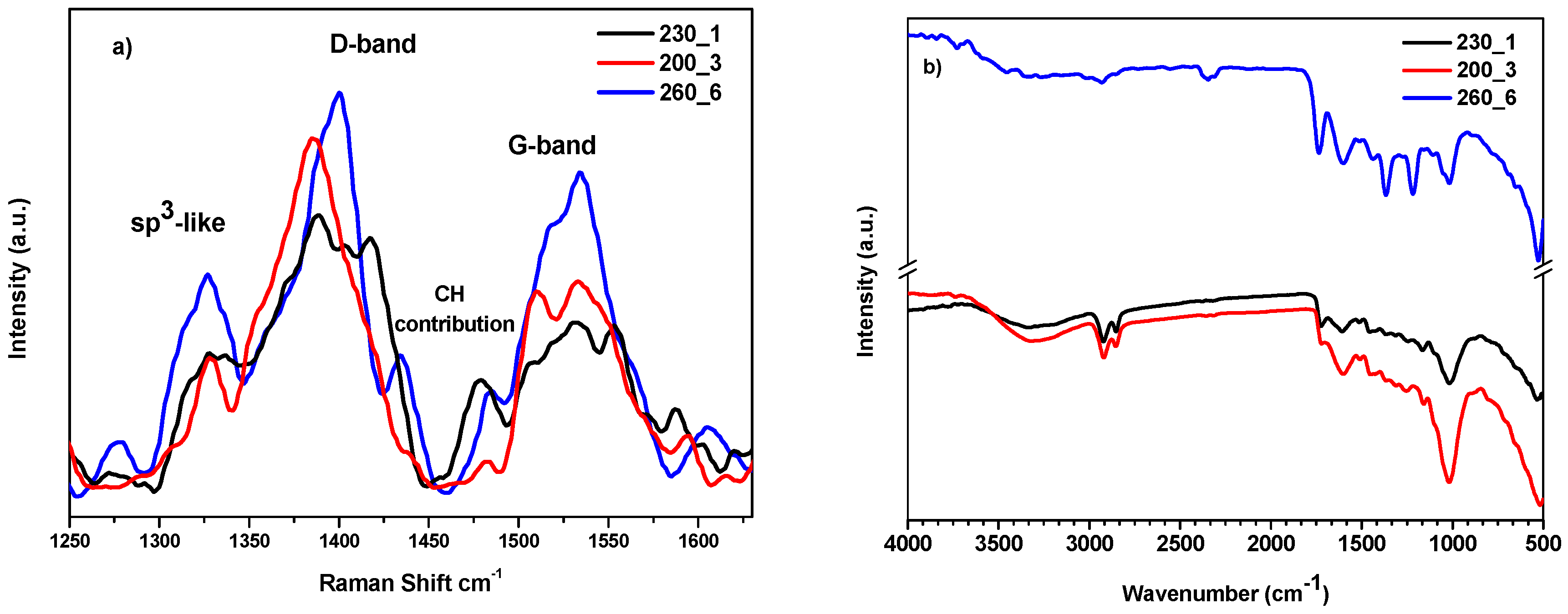
The Raman and the FTIR spectra of the samples are reported in Figure 2. The various carbon materials obtained from hydrochars depend greatly on the ratio between the sp2 (graphite-like) and sp3 (diamond-like) regions. The Raman spectra (Figure 2a) of the samples reflect this dependency and appear very complex showing the typical features of hydrogenated amorphous carbon with graphitic carbon domains [45,46].
The D and G bands can be identified in the spectra. The D band is related to the presence of defects or disorder in the graphite lattice. The G band is associated with the in-plane vibrational motion of the sp2 hybridized carbon atoms in the hexagonal lattice of graphite [47]. Many factors can contribute to the broadening of the signals: (i) the size of carbon clusters: larger clusters may exhibit different vibrational properties compared to smaller ones; (ii) the cluster distribution: variations in the distribution of carbon clusters within the material; (iii) the nature of chemical bonding: changes in bonding configurations, such as the presence of functional groups or impurities. However, it has been observed that in chars obtained at relatively low temperatures and not aged, the D and G bands do not represent graphitic structures or defects but rather polyaromatic rings of different sizes. In particular, the D band at around 1380–1400 cm−1 could be related to fused aromatic rings and the G band at around 1520–1550 cm−1 could be assigned to aromatic ring breathing [48]. This statement seems to be confirmed by the XPS results. The position and relative shift in the D and G bands in Raman spectra can provide information about the structural characteristics of hydrochars. It is mentioned that the shift in these bands is associated with the degree of aromatization, and this is influenced by the temperature of formation [49], although there is controversy regarding the correlation of changes in the D and G bands with the char structure [50]. Comparing the three spectra in Figure 2a, the sample treated at higher temperatures for longer times (260_6) presents a maximum shift in D and G bands and a higher intensity for the G band, indicating an increase in the number or size of crystallites.
Other peaks are present in the Raman spectra: signals centred at 1325 cm−1 are the result of the vibration of sp3 carbons, while at around 1470–1490 cm−1, there is the contribution of C–H vibrations originated from single or fused aromatic rings [45,51].
The FTIR analysis is shown in Figure 2b. The spectra of samples 200_3 and 230_1 seem very similar, while the spectrum of 260_6 shows a different pattern. The hydroxyl band appears at 3000 cm−1 and can provide information about the water content of the different hydrochars, indicating the hygroscopic nature of the material. The intensity of the band is reduced with increasing HTC temperature, higher for samples 200_3 and 230_1, lower for 260_6. Aliphatic C-H stretching vibrations (around 2930 and 2850 cm−1), indicating sp3 carbons, are more pronounced for the samples treated at a low temperature. All the samples show the presence of carboxylic/carbonylic groups at 1735 cm−1, but the peak is more intense for samples 230_1 and 260_6; other peaks are present at 1608 cm−1 corresponding to aromatic C=C stretching. An aromatic C=C ring structure and CH3 deformations are at 1420 and 1370 cm−1, respectively. The sample 260_6 shows a band at 1223 cm−1, slightly visible for the sample 230_1, corresponding to aromatic C-O stretching. Aliphatic ether C–O and alcohol C–O at 1021 cm−1 appear stronger for the sample 230_1 and 200_3 [52,53].
The highly graphitic sample 260_6 has the highest water contact angle (129°, SI, Figure S1), in agreement with the low intensity of the O-H band in the FTIR spectrum, whereas the intermediate value belongs to the sample 230_1 (97°). The lowest value (89°) corresponds to a lower degree of graphitization (200_3) and indicates a higher content of hydrophilic oxygenated surface groups.
In Figure 3 are reported the XPS spectra of the C 1s region for all the samples. The deconvolution of the C 1s signal into four synthetic peaks showed that carbon is mostly present as aliphatic and aromatic carbon (component A, red line) and alcoholic or ether (furans, pyrans, etc.) carbon (component B, blue line) [54]. The other signals are due to ketone and C-N bonds (component C, pink line) and carboxylic carbon (component D, green line).
The intensity distribution of the four components varies with the type of sample as reported in Figure 3. Nitrogen is always present in pyrrolic/aminic/amidic bonds (400.2–400.6 eV) [55,56]. The O 1s spectra, reported in the SI (Figures S2–S4), confirm these assignments.
Comparing the composition reported via XPS with the results of the elemental analysis, it is possible to note that via XPS the carbon/oxygen ratio increases in the order 200_3, 230_1, 260_6, while via elemental analysis, the minimum value is for the 230_1 sample, indicating a greater content of oxygenated groups. In general, in the XPS analysis, the carbon content is higher with respect to the elemental analysis. Considering that XPS is a surface technique, the results suggest a higher concentration of carbon on the surface, in agreement with previous observations [57,58,59].
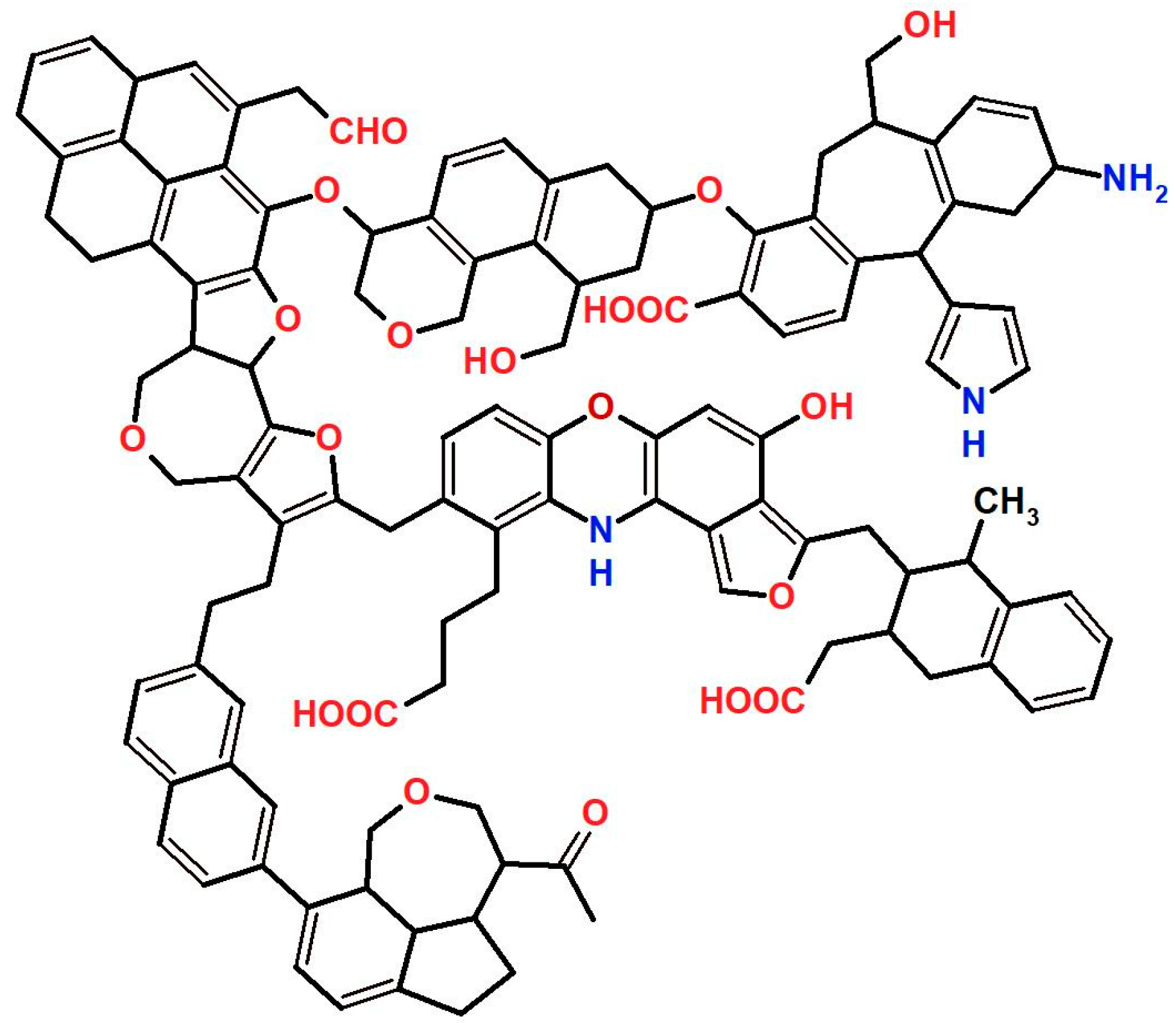
A highly simplified structure of a hydrochar is proposed in Figure 4.
The BET isotherms of the sample 200_3 are characteristic of a macroporous material without micropores; the BET surface area (4.7 m2/g) is typical of non-activated hydrochars. The correlation between the porosity and density was analyzed by Brewer et al. [60]. As reported previously, the porosity of a hydrochar increases until 230 °C, while a higher temperature has a negative response [61]. The densities reported in Table 1 are consistent, with the lowest density observed for the sample 230_1.
The optical micrographs (Figure S5, SI) show that the hydrochar electrodes 200_3 and 260_6 are quite dense, whereas the electrode 230_1 presents a more porous and open microstructure. The hydrochar component is clearly visible on top of the fibrous structure of the carbon paper substrate. The SEM micrographs (Figure S6, SI) confirm this observation.

2.2. Hydrochar Catalytic Electrodes for ORR and CO2RR

A typical cyclovoltammetric determination of a hydrochar electrode’s capacitance in the non-Faradaic region is shown in SI (Figure S7a). The capacitances, obtained from a linear fit of the current vs. scan rate according to the equation, j = C(dU/dt) (Figure S7b), are reported for all the samples in SI (Table S2). These data can be compared with values obtained via impedance spectroscopy. Figure S8 (SI) presents impedance spectra for all the samples determined under the same conditions. The best-fit values of the various equivalent circuit elements are also reported in the SI (Table S2). The electrode 230_1, made using a hydrochar synthesized at an intermediate HTC temperature, has clearly the highest capacitance as corroborated via impedance spectroscopy, with the highest value of the circuit element representing the electrode capacitance (Table S2). This sample presents, thus, the highest electrochemically active surface area (ECSA), which is consistent with the optical and SEM micrographs showing that the layer of sample 230_1 is the most dispersed among the hydrochar electrodes.
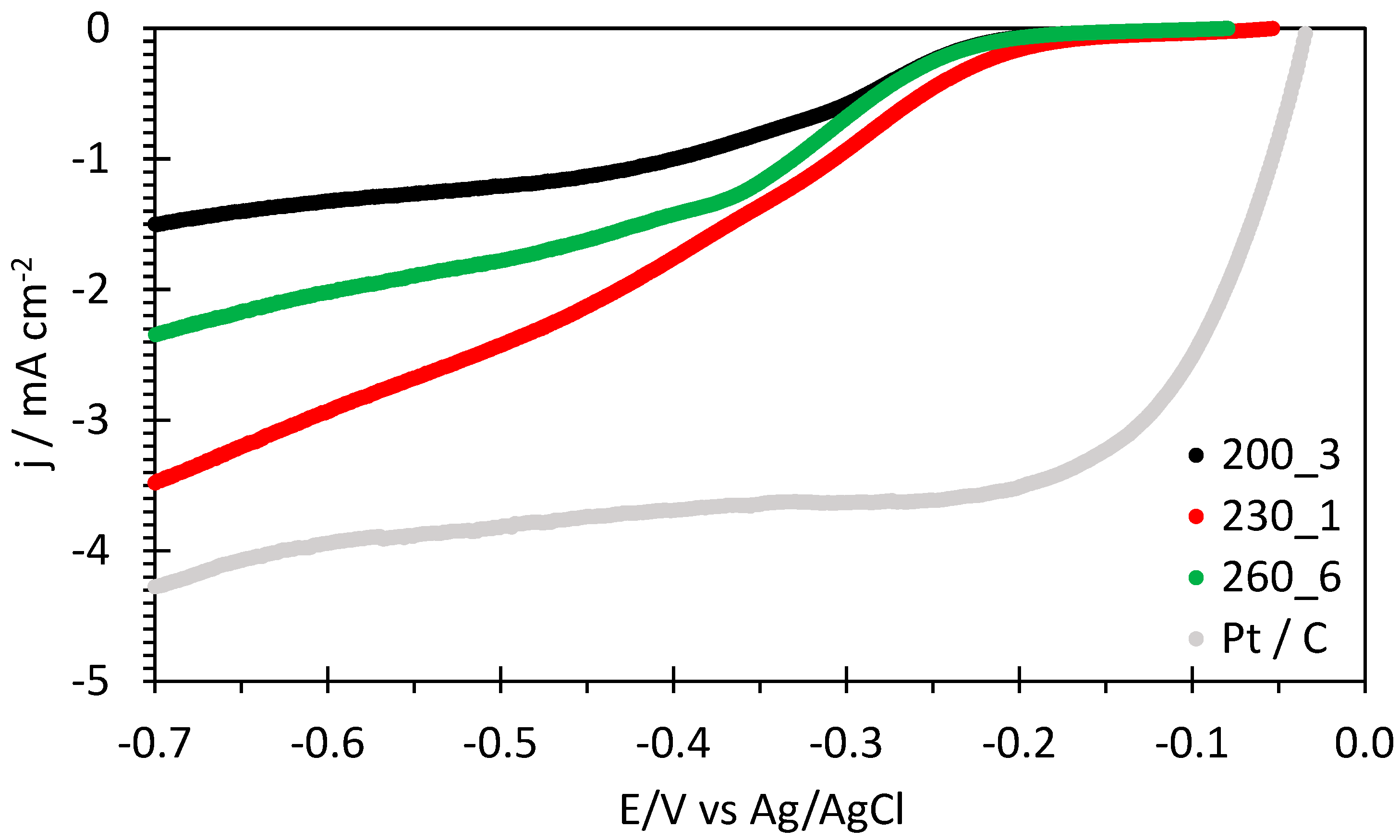
A comparison of linear sweep voltammograms for the oxygen reduction reaction of the hydrochar samples is represented in Figure 5 together with a benchmark Pt/C cloth electrode.
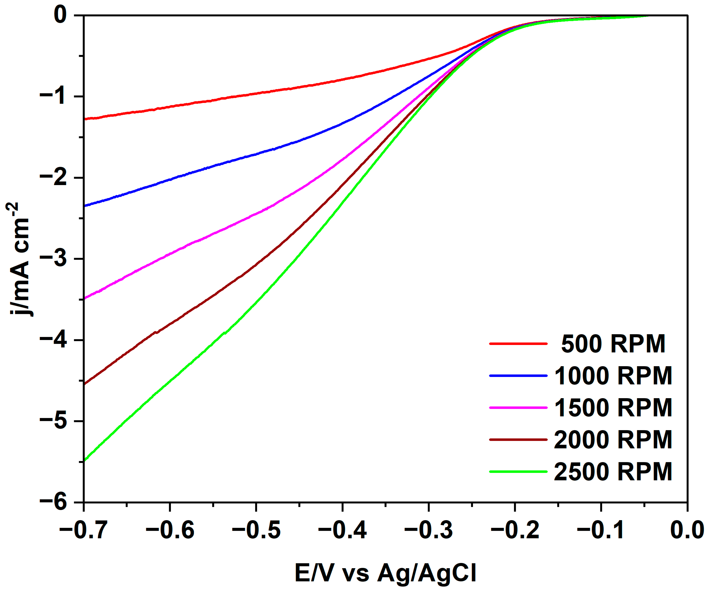
The sample 230_1 has clearly the highest electrocatalytic activity for the ORR, and quite large current densities are attained at 1500 rpm. Linear sweep voltammograms at various RDE speeds are reported in Figure 6. Similar figures for the other hydrochar electrodes are shown in the SI (Figure S9).
Table 2 presents the various electrochemical parameters of the hydrochar electrodes for the ORR in alkaline solution. The potentials vs. the reversible hydrogen electrode (RHE) are calculated from the potential vs. Ag/AgCl according to Equation (1):
E(vs. RHE/V) = E(vs. Ag/AgCl) + 0.197 + 13 × 0.059
The highest onset and half-wave potentials reported in Table 2 are observed for sample 230_1, indicating the best electrocatalytic properties. This onset potential is to our knowledge the highest value reported in the literature for hydrochars (Table 3). The value of 0.9 V vs. RHE reported in [34] refers to a hydrochar treated at 800 °C with a higher energy consumption.
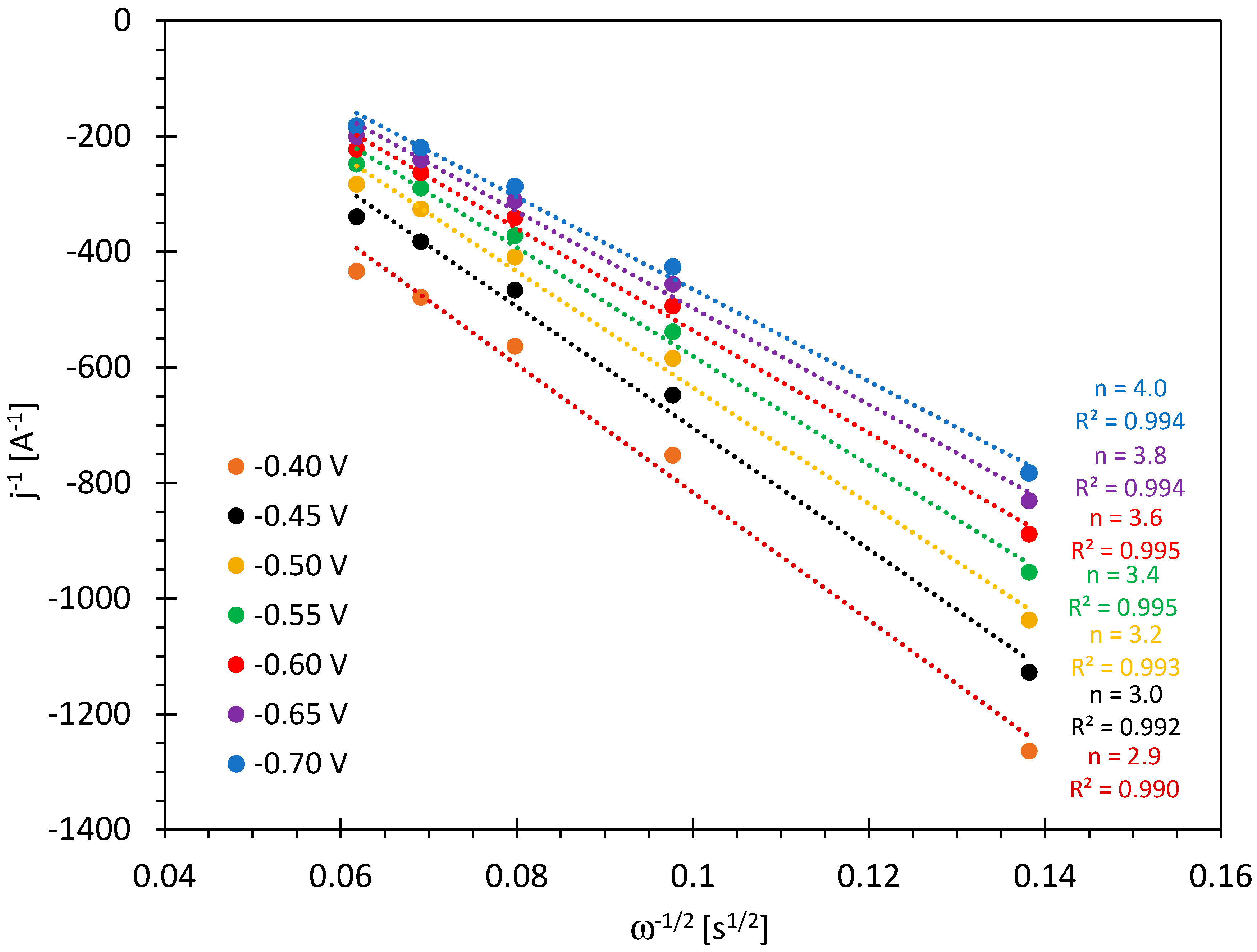
The number of exchanged electrons can be obtained from Koutecky–Levich plots. The plots for the hydrochar electrode 230_1 at various overpotentials are reported in Figure 7. The corresponding figures for the other samples can be found in the supporting information (Figure S10). The number of exchanged electrons increases with the overpotential and reaches four at the highest cathodic potential.
The numbers shown in Table 2 at 0.26 V vs. RHE indicate that the hydrochar 200_3 gives mostly two-electron reduction, whereas the samples 230_1 and 260_6 are able to provide a substantial amount of four-electron reduction.
Finally, the Tafel plots reported in the SI (Figure S11) give slopes indicating two-electron transfer as a rate-determining step; the lower slope for the sample 230_1 (Table 2) is consistent with the better electrocatalytic activity. Altogether, there is a clearly better performance of this sample that can be attributed to a highly electrochemically active surface area, related to the optimal hydrothermal treatment conditions.
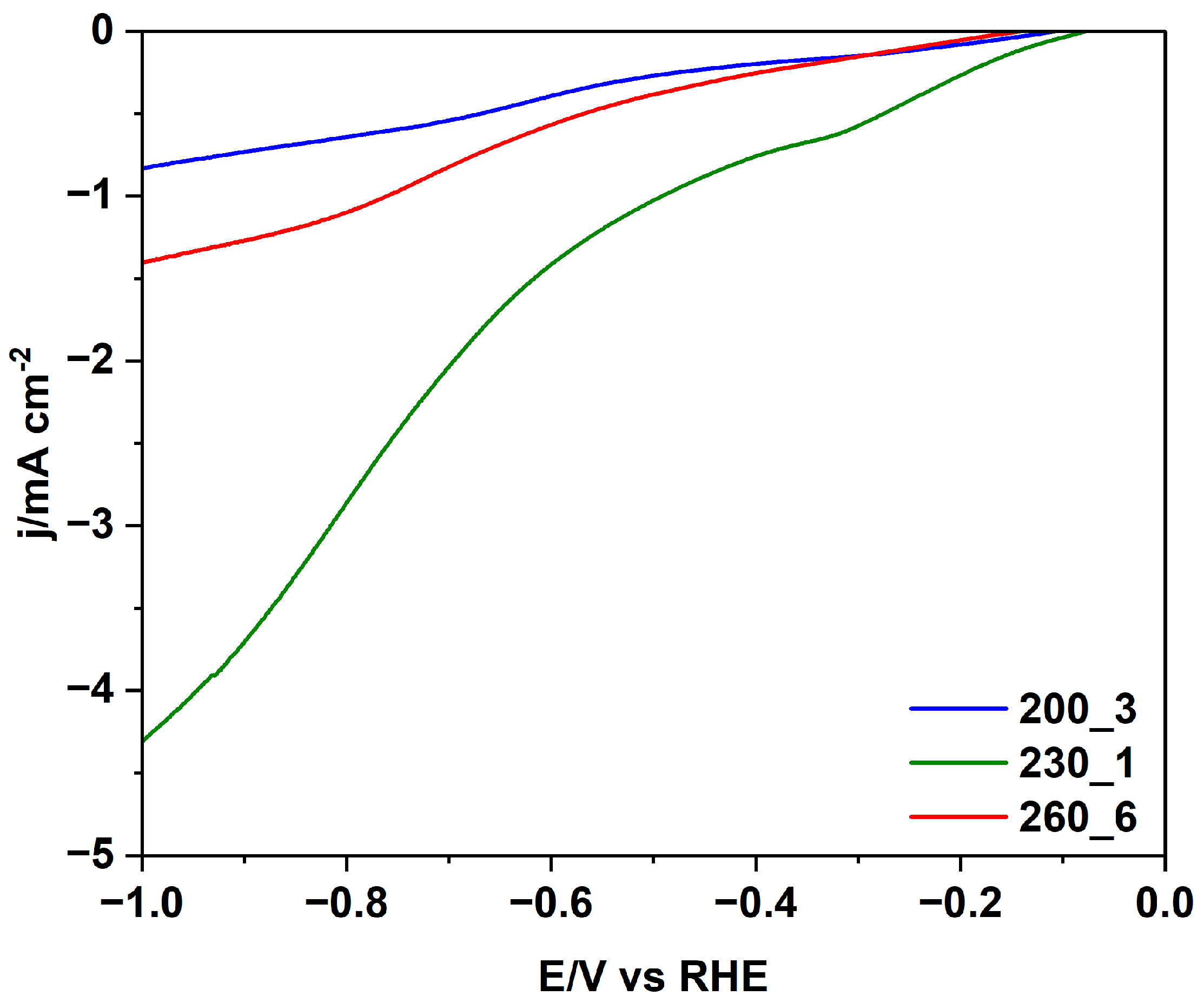
This advantage is also very clearly observed for the CO2 reduction reaction (CO2RR). The comparison of the hydrochar electrodes is shown in Figure 8. There is again a large advantage for sample 230_1 and, as for the ORR, the sample 200_3 presents the lowest performance.
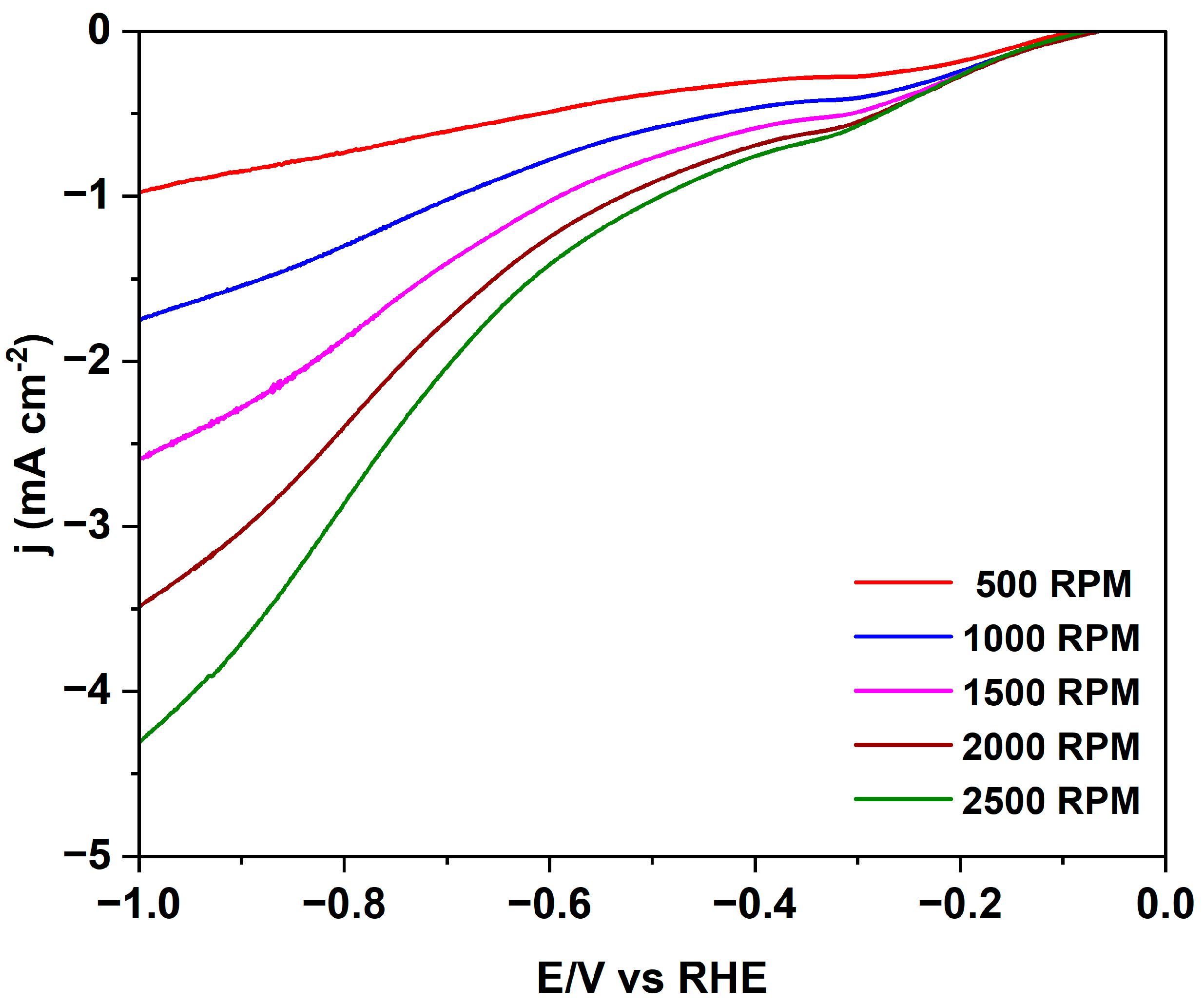
The linear sweep voltammograms at various RDE speeds are shown for hydrochar 230_1 in Figure 9.
Altogether, the LSVs confirm the superior electrocatalytic performance of 230_1 also for the CO2RR. Probably, the optimal porosity of this sample, related to an optimal HTC treatment, explains this result, because the order of current densities is the same as for the ORR, with a much higher current density observed for sample 230_1. CO2 is very sensitive to the presence of “basic” centres, and it is reported in the literature that the N-doping of carbons leads to an increase in the catalytic activity for the CO2RR. However, the hydrochar with the highest nitrogen content according to the elemental analysis (Table 1) does not show the best performance for the CO2RR; a similar result was reported recently by Fu et al. [42].
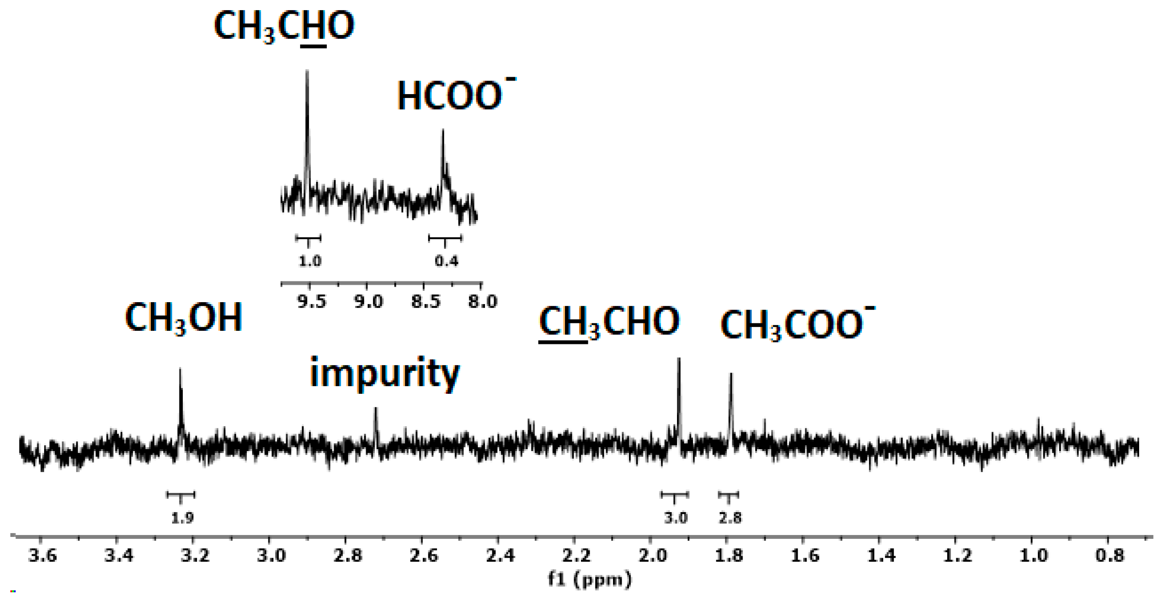
NMR spectroscopy is a powerful investigative method for identifying the liquid products in CO2RR and has a low detection limit (<5 μM for methanol) [63]. The 1H NMR spectrum of sample 230_1 is reported in Figure 10. The spectrum was collected directly from the CO2RR solution using an external lock. In the high-field region, three peaks assigned to acetate, acetaldehyde, and methanol are present. The corresponding signal of acetaldehyde appears at a low field together with formate. Using the three hydrogens of acetaldehyde as an internal standard, the ratios between the products are 1:0.9:0.6:0.4 for acetaldehyde, acetate, methanol, and formate, respectively. In addition to the formation of methanol and formate, the CO2RR with these hydrochar electrodes leads thus to the generation of C2 products providing a means for producing valuable chemicals. The analysis of liquid products using HPLC and gaseous products using gas chromatography is the objective of future research.
By improving the microstructure and dispersion of the deposited hydrochar, one can significantly enhance the electrocatalytic activity (e.g., increase the number of exchanged electrons for the ORR), but also reduce the mass transport limitation of oxygen and CO2 to the active catalytic sites. The data reported here represent a significant improvement of the electrocatalytic performance of hydrochars in comparison with the previous literature, showing the great potential of these materials for electrocatalysis [33,64].
It is important to emphasize the significance of the presence of an excellent anion exchange ionomer (AEI) [44], specifically PPO-LC-TMA, which is crucial in designing high-performance electrodes.

3. Materials and Methods

3.1. Materials

Semi-dried pine needles were collected from an area surrounding the University of Perugia, Italy. The urea supplied by Merck KGaA (Darmstadt, Germany) was used as the nitrogen precursor. Other chemicals were of reagent grade and were used as received from Sigma-Aldrich. Carbon paper (AvCarb EP55) and Pt/C 60% cloth gas diffusion electrodes (0.5 mg/cm2) were purchased from the Fuel Cell Store.

3.2. Synthesis of Hydrochars

3.2.1. Pine Needle Waste Pre-Treatment

Pine needles (PNs) were cut into 1–2 cm pieces and dried at 110 °C for 24 h. The resultant dried biomass was subsequently pulverized, sieved, and subjected to extraction using a toluene–methanol azeotrope in a Soxhlet apparatus for 8 h, achieving a 98% recovery rate. This extraction process aimed to eliminate the oil, waxes, and proteins from the biomass. Following the extraction, any residual solvent traces were efficiently removed under vacuum conditions at 80 °C. The pre-treated feedstock was then directly employed in the subsequent step.

3.2.2. Hydrothermal Carbonization of Pre-Treated PNs with Urea

The synthesis of N-doped hydrochars was conducted using a 30 mL cylindrical pressure reactor fitted with a 13.0 kW/m2 heater and internal sensors for precise temperature control. Pre-treated PNs (2 g) were dispersed in 20 mL of water, supplemented with 0.025 g of sodium dodecyl sulfate (SDS) and 1.8 g of urea in a round-bottomed flask. The mixture underwent stirring at 60 °C and 700 rpm for 20 min before being loaded into the reactor. Subsequently, the reactor heater was activated and set to temperatures of 200 °C, 230 °C, and 260 °C, each for durations of 3, 1, and 6 h, respectively. The resulting hydrochar samples were designated as 200_3, 230_1, and 260_6. After the reaction time, the heater was deactivated, and the reactor was allowed to cool to room temperature, with the pressure reduced to the ambient level. Subsequently, product separation was achieved through filtration, and all the liquids were collected in a separate container. The hydrochar underwent drying in an oven at 105 °C for 24 h, followed by mortar and pestle grinding for 15 min and sieving (<0.3 mm), and finally, it was stored in an airtight container for subsequent analysis. The hydrochar yield was calculated using Equation (2):
Yield (%) = [weight of dried hydrochar (g)/weight of initial biomass (g)] × 100

3.3. Catalytic Ink and Electrode Preparation

The anion exchange polymer used for the ink preparation was poly(2,6-dimethyl-1,4-phenylene oxide) (PPO) with N-pentyl-N,N,N-trimethylammonium side groups, called in the following PPO-LC (Long Chain)-TMA prepared in the LIME lab [65]. The inks for the catalytic layers were prepared from 40 mg of the hydrochar, 10 mg of PPO-LC-TMA (IEC = 0.953 meq/g) [44], and 500 μL of DMSO. The mixtures were left to undergo stirring overnight and then sonicated at RT for 30 min. An aliquot of the resulting pastes was uniformly spread over a layer of carbon paper [44]. The electrodes were vacuum dried at 40 °C for 4 h. The deposited mass was 0.25 ± 0.03 mg for all the samples, corresponding to a hydrochar catalyst loading of 0.7 mg/cm2.

3.4. Characterization

3.4.1. Proximate Composition

The moisture (U), the volatile matter (VM), and the ash content were obtained according to EN ISO 18134-3 [66], EN 15148 [67], and EN 14775 [68], EN 51719 [69], respectively (Table S1, Supplementary Material). The fixed carbon (FC) was calculated using Equation (3):
FC (wt%) = 100 − VM (wt%) − U (wt%) − Ash (wt%)

3.4.2. Elemental Analysis

The elemental composition was determined using a UNICUBE® elemental analyzer (Table 1 and Table S1, SI). The oxygen content was calculated using Equation (4):
O (%) = 100% − (C% + H% + N% + Ash%)

3.4.3. Bulk Density of Hydrochars

The bulk density was calculated according to the guidelines of the European Biochar Certificate [70], analogue VDLUFA-Method A 13.2.1 [71]. A dried, water-free sample of at least 300 mL was poured into a graduated cylinder, and its mass was measured. The sample’s volume was then recorded after it underwent ten compressions through falling. Subsequently, the bulk density (on a dry matter basis) in kg/m3 was calculated using the sample’s mass and volume.

3.4.4. Brunauer–Emmett–Teller (BET) Analysis

The BET surface area was measured via nitrogen gas sorption at 77 K. The samples were vacuum degassed before the analysis.

3.4.5. Water Contact Angle

The sessile drop method was applied using a Biolin Scientific Attension Theta Flex optical tensiometer. Samples of 3 µL of water were deposited at a 0.1 µL/s rate on the electrode surface. The drop shape and contact angle were analyzed according to the Young–Laplace equation, and an average of several experiments was determined.

3.4.6. Microscopical Observations

The optical micrographs were produced using a Leitz Aristomet microscope. The Scanning Electron Micrographs (SEM) were obtained using a ZEISS Gemini SEM 500 at an acceleration voltage of 5 kV.

3.4.7. Spectroscopic Analysis

1H-NMR spectra were recorded using a Bruker Avance 700 spectrometer operating at 700.18 MHz. After the CO2RR, the solution was collected and measured directly using an external look containing D2O. The Fourier Transform Infrared Spectroscopy (FTIR) spectra were obtained using a Perkin Elmer Spectrum 2 IR spectrometer equipped with an ATR ZnSi crystal. The Raman spectra were collected using a Optosky ATR 8300 Micro Raman spectrometer. The excitation wavelength was 785 nm and the laser power was 85 mW. X-Ray Photoelectron Spectra (XPS) were acquired by using an Escalab 250Xi (Thermo Fisher Scientific Ltd., Dartford, UK) with a monochromatic Al Kα (1486.6 eV) source. The powder samples were pressed on pure Au (99.99%) foil. The binding energy (BE) scale was corrected by positioning the C 1s peak of the aliphatic carbon at BE = 285.0 eV and controlling the position of the Fermi level at BE = 0 eV.

3.4.8. Electrochemical Measurements

The three-electrode cell comprised a rotating disk electrode (RDE, 0.28 cm2 area, OrigaTrod, OrigaLys), a 4 cm2 Pt foil as a counter-electrode, and an Ag/AgCl reference electrode (E = 0.197 V vs. NHE). Oxygen-saturated 0.1 M KOH was used as the electrolyte for ORR, and CO2 saturated 0.1 M KHCO3 was used for CO2RR. Cyclic voltammetry (CV), linear sweep voltammetry (LSV), chronoamperometry (CA), and electrochemical impedance spectroscopy (EIS) measurements were performed at room temperature using a Biologic VMP3 potentiostat. The scan rates for the CV and the LSV measurements were 20–100 mV/s and 5 mV/s, respectively. The rotating speeds of the RDE were between 500 and 2500 rpm. The impedance spectra were recorded in a frequency range of 1 Hz–1 MHz (a.c. amplitude = 20 mV).

4. Conclusions

N-doped hydrochar-based catalytic materials were obtained via the hydrothermal carbonization of pine needle waste at moderate temperatures, a process recognized for its energy efficiency compared to the other carbonization methods.
Three different hydrochars were synthesized and mixed with an anion exchange ionomer to prepare an electrode ink used for the ORR and CO2RR. The electrocatalytic performances of the hydrochar synthesized at 230 °C are remarkable for the ORR, exhibiting a four-electron reduction capability and the highest reported value of the onset potential for a hydrochar. This sample exhibited an optimal porosity, and in CO2RR, various C2 products were obtained, including acetaldehyde and acetate, as determined by NMR spectroscopy. The addition of a high-performance hydroxide ion-conducting ionomer to the electrode ink was instrumental in achieving such high electrocatalytic performances.
Overall, the development of biomass-waste-derived hydrochar-based catalytic electrodes via low-energy hydrothermal carbonization represents a significant advancement in the field of sustainable catalysis. This represents the first report on catalytic electrodes simultaneously incorporating both a hydrochar and AEI.

Supplementary Materials

The following supporting information can be downloaded at https://www.mdpi.com/article/10.3390/molecules29143286/s1: Elemental and proximate analyses, water contact angle measurements, XPS measurements, optical micrographs, and SEM images for hydrochars; plots and data concerning electrode capacitance; impedance spectra; voltammograms for ORR and CO2RR; Koutecky–Levich and Tafel plots.

Author Contributions

Conceptualization, A.M. and M.L.D.V.; data curation, S.C. and S.S.; formal analysis, E.C. and E.S.; funding acquisition, M.L.D.V.; investigation, E.C., S.C., E.S., S.K., S.S. and F.V.; methodology, A.M., F.V., P.K. and M.L.D.V.; resources, A.M., L.V., P.K. and M.L.D.V.; supervision, M.L.D.V.; validation, E.C., S.C., E.S., S.K., S.S. and F.V.; visualization, A.M., E.C. and M.L.D.V.; writing—original draft, A.M., E.S. and M.L.D.V.; writing—review and editing, A.M., E.S., S.K., L.V., F.V., P.K. and M.L.D.V. All authors have read and agreed to the published version of the manuscript.

Funding

A.M.: S.C., E.S. and M.L.DV gratefully thank the European Union-NextGenerationEU-National Recovery and Resilience Plan (NRRP)–MISSION 4 COMPONENT 2, INVESTMENT N. 1.1, CALL PRIN 2022 D.D. 104 02-02-2022–(GreenCore) (CUP N: E53D23001030006, J53D23000910006). E.C. is funded by PhD scholarship D.M. 351/2022 (M4C1–Inv. 3.4, 4.1)/NRRP Research.

Institutional Review Board Statement

Not applicable.

Informed Consent Statement

Not applicable.

Data Availability Statement

Data are contained within the article or Supplementary Materials.

Acknowledgments

The authors thank Dr. Emily Bloch (UMR Madirel) for the BET analysis.

Conflicts of Interest

The authors declare no conflicts of interest.

References

  1. Seow, Y.X.; Tan, Y.H.; Mubarak, N.M.; Kansedo, J.; Khalid, M.; Ibrahim, M.L.; Ghasemi, M. A review on biochar production from different biomass wastes by recent carbonization technologies and its sustainable applications. J. Environ. Chem. Eng. 2022, 10, 107017. [Google Scholar] [CrossRef]
  2. Ghodake, G.S.; Shinde, S.K.; Kadam, A.A.; Saratale, R.G.; Saratale, G.D.; Kumar, M.; Palem, R.R.; Al-Shwaiman, H.A.; Elgorban, A.M.; Syed, A.; et al. Review on biomass feedstocks, pyrolysis mechanism and physicochemical properties of biochar: State-of-the-art framework to speed up vision of circular bioeconomy. J. Clean. Prod. 2021, 297, 126645. [Google Scholar] [CrossRef]
  3. Correa, C.R.; Hehr, T.; Voglhuber-Slavinsky, A.; Rauscher, Y.; Kruse, A. Pyrolysis vs. hydrothermal carbonization: Understanding the effect of biomass structural components and inorganic compounds on the char properties. J. Anal. Appl. Pyrolysis 2019, 140, 137–147. [Google Scholar] [CrossRef]
  4. Liu, W.J.; Jiang, H.; Yu, H.Q. Development of Biochar-Based Functional Materials: Toward a Sustainable Platform Carbon Material. Chem. Rev. 2015, 115, 12251–12285. [Google Scholar] [CrossRef] [PubMed]
  5. Lyu, H.; Lim, J.Y.; Zhang, Q.R.; Senadheera, S.S.; Zhang, C.C.; Huang, Q.L.; Ok, Y.S. Conversion of organic solid waste into energy and functional materials using biochar catalyst: Bibliometric analysis, research progress, and directions. Appl. Catal. B 2024, 340, 123223. [Google Scholar] [CrossRef]
  6. Lee, J.; Kim, K.H.; Kwon, E.E. Biochar as a Catalyst. Renew. Sustain. Energy Rev. 2017, 77, 70–79. [Google Scholar] [CrossRef]
  7. Xiong, X.N.; Yu IK, M.; Cao, L.C.; Tsang DC, W.; Zhang, S.C.; Ok, Y.S. A review of biochar-based catalysts for chemical synthesis, biofuel production, and pollution control. Bioresour. Technol. 2017, 246, 254–270. [Google Scholar] [CrossRef] [PubMed]
  8. Cao, X.F.; Sun, S.N.; Sun, R.C. Application of biochar-based catalysts in biomass upgrading: A review. RSC Adv. 2017, 7, 48793–48805. [Google Scholar] [CrossRef]
  9. Zhao, S.; Wang, X.; Wang, Q.; Sumpradit, T.; Khan, A.; Zhou, J.; Salama, E.-S.; Li, X.; Qu, J. Application of biochar in microbial fuel cells: Characteristic performances, electron-transfer mechanism, and environmental and economic assessments. Ecotoxicol. Environ. Saf. 2023, 267, 115643. [Google Scholar] [CrossRef]
  10. Bhatia, S.K.; Palai, A.K.; Kumar, A.; Bhatia, R.K.; Patel, A.K.; Thakur, V.K.; Yang, Y.H. Trends in renewable energy production employing biomass-based biochar. Bioresour. Technol. 2021, 340, 125644. [Google Scholar] [CrossRef]
  11. Senthil, C.; Lee, C.W. Biomass-derived biochar materials as sustainable energy sources for electrochemical energy storage devices. Renew. Sustain. Energy Rev. 2021, 137, 110464. [Google Scholar] [CrossRef]
  12. Arauzo, P.J.; Maziarka, P.A.; Schoder, K.A.; Pfersich, J.; Ronsse, F.; Kruse, A. Influence of sequential HTC pre-treatment and pyrolysis on wet food-industry wastes: Optimisation toward nitrogen-rich hierarchical carbonaceous materials intended for use in energy storage solutions. Sci. Total Environ. 2022, 816, 151648. [Google Scholar] [CrossRef]
  13. Khosravi, A.; Zheng, H.; Liu, Q.; Hashemi, M.; Tang, Y.Z.; Xing, B.S. Production and characterization of hydrochars and their application in soil improvement and environmental remediation. Chem. Eng. J. 2022, 430, 133142. [Google Scholar] [CrossRef]
  14. Becker, G.C.; Wüst, D.; Köhler, H.; Lautenbach, A.; Kruse, A. Novel approach of phosphate-reclamation as struvite from sewage sludge by utilising hydrothermal carbonization. J. Environ. Manag. 2019, 238, 119–125. [Google Scholar] [CrossRef]
  15. Marin-Batista, J.D.; Mohedano, A.F.; Rodríguez, J.J.; de la Rubia, M.A. Energy and phosphorous recovery through hydrothermal carbonization of digested sewage sludge. Waste Manag. 2020, 105, 566–574. [Google Scholar] [CrossRef] [PubMed]
  16. Kumar, M.; Dutta, S.; You, S.M.; Luo, G.; Zhang, S.C.; Show, P.L.; Sawarkar, A.D.; Singh, L.; Tsang, D.C.W. A critical review on biochar for enhancing biogas production from anaerobic digestion of food waste and sludge. J. Clean. Prod. 2021, 305, 127143. [Google Scholar] [CrossRef]
  17. Diaz, E.; Manzano, F.J.; Villamil, J.; Rodriguez, J.J.; Mohedano, A.F. Low-Cost Activated Grape Seed-Derived Hydrochar through Hydrothermal Carbonization and Chemical Activation for Sulfamethoxazole Adsorption. Appl. Sci. 2019, 9, 5127. [Google Scholar] [CrossRef]
  18. Alhnidi, M.J.; Straten, J.W.; Nicolae, S.A.; Hoffmann, V.; Titirici, M.M.; Kruse, A. Thermal treatment versus hydrothermal carbonization: How to synthesize nitrogen-enriched carbon materials for energy storage applications? Int. J. Energy Res. 2022, 46, 1622–1636. [Google Scholar] [CrossRef]
  19. Zhuang, X.Z.; Liu, J.G.; Ma, L.L. Facile synthesis of hydrochar-supported catalysts from glucose and its catalytic activity towards the production of functional amines. Green Energy Environ. 2023, 8, 1358–1370. [Google Scholar] [CrossRef]
  20. Wang, J.; Chen, S.; Xu, J.Y.; Liu, L.C.; Zhou, J.C.; Cai, J.J. High-surface-area porous carbons produced by the mild KOH activation of a chitosan hydrochar and their CO2 capture. New Res. Carbon Mater. 2021, 36, 1081–1093. [Google Scholar] [CrossRef]
  21. Esteban, D.A.; Martínez, A.G.; González, J.C.; Birss, V.I.; Otero-Díaz, L.C.; Brande, D.A. Tunable Supercapacitor Materials Derived from Hydrochar/Gold Nanograpes. ACS Appl. Energy Mater. 2020, 3, 9348–9359. [Google Scholar] [CrossRef]
  22. Zhou, Y.; Shi, W.K.; Engler, N.; Nelles, M. High-value utilization of kitchen waste derived hydrochar in energy storage regulated by circulating process water. Energy Convers. Manag. 2021, 229, 113737. [Google Scholar] [CrossRef]
  23. Li, K.; Liu, Y.Q.; Cui, B.; Sima, D.W.; Wang, D.; Ye, Y.Y.; Li, S.R.; Zheng, Z.F. Nitrogen reduction to ammonia at ambient conditions using hydrochar prepared from cigarette filters as catalyst. Int. J. Hydrogen Energy 2020, 45, 20875–20882. [Google Scholar] [CrossRef]
  24. Mai, D.D.; Wen, R.; Cao, W.M.; Yuan, B.; Liu, Y.; Liu, Q.; Qian, G.R. Effect of Heavy Metal (Zn) on Redox Property of Hydrochar Produced from Lignin, Cellulose, and D-Xylose. ACS Sustain. Chem. Eng. 2017, 5, 3499–3508. [Google Scholar] [CrossRef]
  25. Reza, M.T.; Lynam, J.G.; Uddin, M.H.; Coronella, C.J. Hydrothermal carbonization: Fate of inorganics. Biomass Bioenergy 2013, 49, 86–94. [Google Scholar] [CrossRef]
  26. Feng, X.; Bai, Y.; Liu, M.Q.; Li, Y.; Yang, H.Y.; Wang, X.R.; Wu, C. Untangling the respective effects of heteroatom-doped carbon materials in batteries, supercapacitors and the ORR to design high performance materials. Energy Environ. Sci. 2021, 14, 2036–2089. [Google Scholar] [CrossRef]
  27. Pietrzak, R.; Wachowska, H.; Nowicki, P. Preparation of nitrogen-enriched activated carbons from brown coal. Energy Fuels 2006, 20, 1275–1280. [Google Scholar] [CrossRef]
  28. Choi, J.; Zequine, C.; Bhoyate, S.; Lin, W.; Li, X.L.; Kahol, P.; Gupta, R. Waste Coffee Management: Deriving High-Performance Supercapacitors Using Nitrogen-Doped Coffee-Derived Carbon. C J. Carbon Res. 2019, 5, 44. [Google Scholar] [CrossRef]
  29. Park, S.; Choi, M.S.; Park, H.S. Nitrogen-doped nanoporous carbons derived from lignin for high CO2 capacity. Carbon Lett. 2019, 29, 289–296. [Google Scholar] [CrossRef]
  30. Quan, C.; Jia, X.Y.; Gao, N.B. Nitrogen-doping activated biomass carbon from tea seed shell for CO2 capture and supercapacitor. Int. J. Energy Res. 2020, 44, 1218–1232. [Google Scholar] [CrossRef]
  31. Hu, X.; Liu, W.J.; Ma, L.L.; Yu, H.Q. Sustainable Conversion of Harmful Algae Biomass into a CO2 Reduction Electrocatalyst for Two-Fold Carbon Utilization. Environ. Sci. Technol. 2023, 57, 1157–1166. [Google Scholar] [CrossRef]
  32. Yuan, H.R.; Qian, X.; Luo, B.; Wang, L.F.; Deng, L.F.; Chen, Y. Carbon dioxide reduction to multicarbon hydrocarbons and oxygenates on plant moss-derived, metal-free, in situ nitrogen-doped biochar. Sci. Total Environ. 2020, 739, 140340. [Google Scholar] [CrossRef]
  33. Amelia, S.T.W.; Nurtono, T.; Setyawan, H.; Widiyastuti, W. Electrocapacitive and electrocatalytic performances of hydrochar prepared by one-step hydrothermal carbonization without further activation. Mater. Res. Express 2023, 10, 075602. [Google Scholar] [CrossRef]
  34. Upskuviene, D.; Balciunaite, A.; Drabavicius, A.; Jasulaitiene, V.; Niaura, G.; Talaikis, M.; Plavniece, A.; Dobele, G.; Volperts, A.; Zhurinsh, A.; et al. Synthesis of nitrogen-doped carbon catalyst from hydrothermally carbonized wood chips for oxygen reduction. Catal. Commun. 2023, 184, 106797. [Google Scholar] [CrossRef]
  35. Nagappan, S.; Duraivel, M.; Hira, S.A.; Prabakar, K.; Ha, C.-S.; Joo, S.H.; Nam, K.M.; Park, K.H. Heteroatom-doped nanomaterials/core–shell nanostructure based electrocatalysts for the oxygen reduction reaction. J. Mater. Chem. A 2022, 10, 987–1021. [Google Scholar] [CrossRef]
  36. Nallayagari, A.R.; Sgreccia, E.; Pasquini, L.; Vacandio, F.; Kaciulis, S.; Di Vona, M.L.; Knauth, P. Catalytic electrodes for the oxygen reduction reaction based on co-doped (B-N, Si-N, S-N) carbon quantum dots and anion exchange ionomer. Electrochim. Acta 2022, 427, 140861. [Google Scholar] [CrossRef]
  37. Rao, P.; Wang, T.-J.; Li, J.; Deng, P.L.; Shen, Y.J.; Yu, C.; Tian, X.-L. Plasma-induced Fe-Nx active sites to improve the oxygen reduction reaction performance. Adv. Sensor Energy Mater. 2022, 1, 100005. [Google Scholar] [CrossRef]
  38. Jiang, M.; Yu, X.; Yang, H.; Chen, S. Optimization strategies of preparation of biomass-derived carbon electrocatalyst for boosting oxygen reduction reaction: A minireview. Catalysts 2020, 10, 1472. [Google Scholar] [CrossRef]
  39. Sekhon, S.S.; Lee, J.; Park, J.-S. Biomass-derived bifunctional electrocatalysts for oxygen reduction and evolution reaction: A review. J. Energy Chem. 2022, 65, 149–172. [Google Scholar] [CrossRef]
  40. Zhang, S.B.; Zhang, X.; Zhang, S.Y.; Zhang, J.J.; Li, G.Y.; He, Y.; Shao, J.A.; Zhang, S.H.; Yang, H.P.; Chen, H.P. Biomass-derived functional carbon material for CO2 adsorption and electrochemical CO2 reduction reaction. Carbon Capture Sci. Technol. 2023, 9, 100135. [Google Scholar] [CrossRef]
  41. Tan, Y.; Jia, S.; Tan, J.; Leow, Y.; Zheng, R.; Tan, X.Y.; Dolmanan, S.B.; Zhang, M.; Yew, P.Y.M.; Ni, X.P.; et al. Coconut husk-derived biochar for enhancing electrochemical conversion of CO2. Mater. Today Chem. 2023, 30, 101595. [Google Scholar] [CrossRef]
  42. Fu, S.L.; Li, M.; de Jong, W.; Kortlever, R. Tuning the Properties of N-Doped Biochar for Selective CO2 Electroreduction to CO. ACS Catal. 2023, 13, 10309–10323. [Google Scholar] [CrossRef]
  43. Borghei, M.; Lehtonen, J.; Liu, L.; Rojas, O.J. Advanced Biomass-Derived Electrocatalysts for the Oxygen Reduction Reaction. Adv. Mater. 2018, 30, 1703691. [Google Scholar] [CrossRef] [PubMed]
  44. Nallayagari, A.R.; Sgreccia, E.; Pasquini, L.; Sette, M.; Knauth, P.; Di Vona, M.L. Impact of Anion Exchange Ionomers on the Electrocatalytic Performance for the Oxygen Reduction Reaction of B-N Co-doped Carbon Quantum Dots on Activated Carbon. ACS Appl. Mater. Interfaces 2022, 14, 46537–46547. [Google Scholar] [CrossRef] [PubMed]
  45. Brown, A.V.; Tompsett, G.A.; Partopour, B.; Deskins, N.A.; Timko, M.T. Hydrochar structural determination from artifact-free Raman analysis. Carbon 2020, 167, 378–387. [Google Scholar] [CrossRef]
  46. Sevilla, M.; Fuertes, A.B. Chemical and Structural Properties of Carbonaceous Products Obtained by Hydrothermal Carbonization of Saccharides. Chem. Eur. J. 2009, 15, 4195–4203. [Google Scholar] [CrossRef] [PubMed]
  47. Wang, Y.; Alsmeyer, D.C.; McCreery, R.L. Raman-spectroscopy of carbon materials-structural basis of observed spectra. Chem. Mater. 1991, 2, 557–563. [Google Scholar] [CrossRef]
  48. Yu, J.; Sun, L.S.; Berrueco, C.; Fidalgo, B.; Paterson, N.; Millan, M. Influence of temperature and particle size on structural characteristics of chars from Beechwood pyrolysis. J. Anal. Appl. Pyrolysis 2018, 130, 127–134. [Google Scholar] [CrossRef]
  49. Xu, J.; Liu, J.; Ling, P.; Zhang, X.; Xu, K.; He, L.; Wang, Y.; Su, S.; Hu, S.; Xiang, J. Raman spectroscopy of biochar from the pyrolysis of three typical Chinese biomasses: A novel method for rapidly evaluating the biochar property. Energy 2020, 202, 117644. [Google Scholar] [CrossRef]
  50. Potgieter-Vermaak, S.; Maledi, N.; Wagner, N.; Van Heerden, J.H.P.; Van Grieken, R.; Potgieter, J.H. Raman spectroscopy for the analysis of coal: A review. J. Raman Spectrosc. 2011, 42, 123–129. [Google Scholar] [CrossRef]
  51. Brown, A.B.; McKeogh, B.J.; Tompsett, G.A.; Lewis, R.; Deskins, N.A.; Timko, M.T. Structural analysis of hydrothermal char and its models by density functional theory simulation of vibrational spectroscopy. Carbon 2017, 125, 614–629. [Google Scholar] [CrossRef]
  52. Ray, A. Characterization of Biochars from Various Agricultural By-Products Using FTIR Spectroscopy, SEM focused with image Processing. IJAEB 2020, 13, 423–430. [Google Scholar] [CrossRef]
  53. Sahoo, S.S.; Vijay, V.K.; Chandra, R.; Kumar, H. Production and characterization of biochar produced from slow pyrolysis of pigeon pea stalk and bamboo. Clean. Eng. Technol. 2021, 3, 100101. [Google Scholar] [CrossRef]
  54. Ganguly, A.; Sharma, S.; Papakonstantinou, P.; Hamilton, J. Probing the Thermal Deoxygenation of Graphene Oxide Using High-Resolution In Situ X-ray-Based Spectroscopies. J. Phys. Chem. C 2011, 115, 17009–17019. [Google Scholar] [CrossRef]
  55. Abe, T.; Watanabe, A. X-ray photoelectron spectroscopy of nitrogen functional groups in soil humic acids. Soil Sci. 2004, 169, 35–43. [Google Scholar] [CrossRef]
  56. Singh, B.; Fang, Y.Y.; Cowie, B.C.C.; Thomsen, L. NEXAFS and XPS characterisation of carbon functional groups of fresh and aged biochars. Org. Geochem. 2014, 77, 1–10. [Google Scholar] [CrossRef]
  57. Fajardo-Díaz, J.L.; Rodríguez-Corvera, C.L.; Muñoz-Sandoval, E.; López-Urías, F. Furan and Pyran Functional Groups Driven the Surface of Nitrogen-Doped Nanofiber Sponges. Chemnanomat 2020, 6, 672–684. [Google Scholar] [CrossRef]
  58. Cheng, F.; Li, X.W. Preparation and Application of Biochar-Based Catalysts for Biofuel Production. Catalysts 2018, 8, 346. [Google Scholar] [CrossRef]
  59. Shi, N.; Liu, Q.Y.; He, X.; Wang, G.; Chen, N.; Peng, J.Y.; Ma, L.L. Molecular Structure and Formation Mechanism of Hydrochar from Hydrothermal Carbonization of Carbohydrates. Energy Fuels 2019, 33, 9904–9915. [Google Scholar] [CrossRef]
  60. Brewer, C.E.; Chuang, V.J.; Masiello, C.A.; Gonnermann, H.; Gao, X.D.; Dugan, B.; Driver, L.E.; Panzacchi, P.; Zygourakis, K.; Davies, C.A. New approaches to measuring biochar density and porosity. Biomass Bioenergy 2014, 66, 176–185. [Google Scholar] [CrossRef]
  61. Kambo, H.S.; Dutta, A.A. Comparative review of biochar and hydrochar in terms of production, physico-chemical properties and applications. Renew. Sustain. Energy Rev. 2015, 45, 359–378. [Google Scholar] [CrossRef]
  62. Panganoron, H.O.; Pascasio, J.D.A.; Esparcia, E.A., Jr.; del Rosario, J.A.D.; Ocon, J.D. Hydrothermally Carbonized Waste Biomass as Electrocatalyst Support for α-MnO2 in Oxygen Reduction Reaction. Catalysts 2020, 10, 177. [Google Scholar] [CrossRef]
  63. Bertheussen, E.; Abghoui, Y.; Jovanov, Z.P.; Varela, A.S.; Stephens, I.E.L.; Chorkendorff, I. Quantification of liquid products from the electroreduction of CO2 and CO using static headspace-gas chromatography and nuclear magnetic resonance spectroscopy. Catal. Today 2017, 288, 54–62. [Google Scholar] [CrossRef]
  64. Rois, M.F.; Sasono, S.R.A.; Widiyastuti, W.; Nurtono, T.; Setyawan, H. High-performance electrocatalyst made from lignosulfonate nanofiber composited with manganese dioxide without carbonation process. Adv. Powder Technol. 2022, 33, 103572. [Google Scholar] [CrossRef]
  65. Becerra-Arciniegas, R.A.; Narducci, R.; Ercolani, G.; Sgreccia, E.; Pasquin, L.; Di Vona, M.L.; Knauth, P. Model Long Side-Chain PPO-Based Anion Exchange Ionomers: Properties and Alkaline Stability. J. Phys. Chem. C 2020, 124, 1309–1316. [Google Scholar] [CrossRef]
  66. ISO 18134-3:2023; Solid Biofuels. Determination of Moisture Content. Part 3: Moisture in General Analysis Sample. International Organization for Standardization: Geneva, Switzerland, 2023.
  67. ISO 18123:2023; Solid Biofuels. Determination of Volatile Matter. International Organization for Standardization: Geneva, Switzerland, 2023.
  68. ISO 18122:2022; Solid Biofuels. Determination of Ash Content. International Organization for Standardization: Geneva, Switzerland, 2022.
  69. DIN 51719:1997-07; Testing of Solid Fuels-Solid Mineral Fuels-Determination of Ash Content. Deutsches Institut für Normung: Berlin, German, 1997.
  70. European Biochar Certificate (EBC). Richtlinien für Die Zertifizierung von Pflanzenkohle; Ithaka Institute: Arbaz, Switzerland, 2012; Version 9.3G vom 11; Available online: http://www.european-biochar.org (accessed on 20 May 2024).
  71. Vdlufa, V.M.A. Available online: https://www.vdlufa.de/Methodenbuch/index.php?option=com_content&view=article&id=7&Itemid=108&lang=de&lang=de (accessed on 20 May 2024).
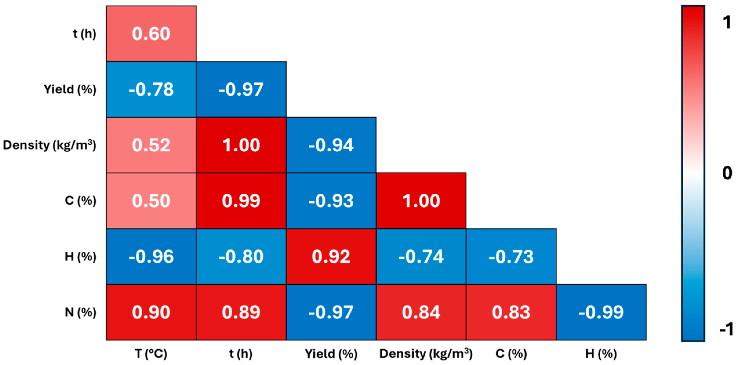
Figure 1. Correlogram of HTC temperature (°C), time (h), HC yield, density, C (%); H (%); N (%).
Molecules 29 03286 g001
Figure 2. (a) Raman and (b) FTIR spectra of the samples.
Molecules 29 03286 g002
Figure 3. XPS spectra of the C 1s region for the samples (a) 200_3; (b) 230_1; (c) 260_6.
Molecules 29 03286 g003
Figure 4. Schematic structure of hydrochar. In red, the oxygenated functionalities; in blue, the nitrogen functionalities.
Molecules 29 03286 g004
Figure 5. Comparison of linear sweep voltammograms for the oxygen reduction reaction of hydrochar electrodes and a benchmark Pt/C cloth electrode at 1500 rpm RDE speed in oxygen-saturated 0.1 M KOH solution.
Molecules 29 03286 g005
Figure 6. Linear sweep voltammograms of a 230_1 hydrochar electrode for the ORR in oxygen-saturated 0.1 M KOH at various RDE speeds.
Molecules 29 03286 g006
Figure 7. Koutecky–Levich plots for the electrode 230_1 at 1500 rpm RDE speed in oxygen-saturated 0.1 M KOH for different electrode potentials (E/V vs. Ag/AgCl). The number of exchanged electrons is indicated for each straight line.
Molecules 29 03286 g007
Figure 8. Comparison of linear sweep voltammograms of hydrochar electrodes for the CO2RR in CO2-saturated 0.1 M KHCO3 at 2500 rpm RDE speed.
Molecules 29 03286 g008
Figure 9. Linear sweep voltammograms of sample 230_1 for the CO2RR in CO2-saturated 0.1 M KHCO3 at various RDE speeds.
Molecules 29 03286 g009
Figure 10. 1H NMR spectrum of the solution after CO2RR with hydrochar sample 230_1.
Molecules 29 03286 g010
Table 1. HTC experimental conditions 1 for the synthesis of the different hydrochars and their corresponding yield, density, and elemental analysis.
SampleT (°C)Time (h)Yield (%)δ (kg/m3)C (%)H (%)N (%)O 2 (%)
200_320036022449.725.492.3437.85
230_123016113645.705.312.5039.51
260_626065532053.684.754.4531.79
1 pine needles: urea = 1:0.9 wt/wt ratio. 2 Calculated by difference.
Table 2. Electrochemical properties of hydrochar electrodes for the ORR in oxygen-saturated 0.1 M KOH. Eonset and E1/2 are the onset and half-wave potentials vs. RHE, n is the number of exchanged electrons for the ORR (at 0.26 V vs. RHE), and b is the Tafel slope.
SampleEonset ORR vs. RHE/VE1/2 ORR vs. RHE/Vn ORRB ORR/mV
200_30.900.671.85114
230_10.920.693.97106
260_60.900.673.63114
Table 3. Comparison of the onset potential (Eonset) and number of exchanged electrons (n) of hydrochars from this work and from the literature.
Hydrochar
(Synthesis Conditions)
Biomass SourceEonset (V/RHE)n Ref.
230 °C 1 h (230_1)pine needles0.92 3.97 at 0.26 V/RHEThis
work
200 °C 12 h, treated in KMnO4 and H2SO4 (pH~3) extracted avocado seedN/A1.83 at 0.46 V/RHE[33]
200 °C 12 h, treated in KMnO4 and NH4OH (pH~9)extracted avocado seedN/A2.21 at 0.46 V/RHE[33]
800 °C, N-dopedwood chips0.90 ~4 in the range 0.30–0.65 V/RHE[34]
250 °C 12 h, activated in KOH and incorporation of MnO2 corncobs0.73 3.27 at 0.21 V/RHE [62]
250 °C 12 h, activated in KOH and incorporation of MnO2coffee waste grounds0.71 3.45 at 0.21 V/RHE[63]
250 °C 12 h, activated in KOH and incorporation of MnO2rice hull0.61 2.84 at 0.21 V/RHE[63]
250 °C 12 h, activated in KOH and incorporation of MnO2coconut sawdust0.60 3.23 at 0.21 V/RHE[63]
Disclaimer/Publisher’s Note: The statements, opinions and data contained in all publications are solely those of the individual author(s) and contributor(s) and not of MDPI and/or the editor(s). MDPI and/or the editor(s) disclaim responsibility for any injury to people or property resulting from any ideas, methods, instructions or products referred to in the content.