Article

Investigating the Electrochemical Performance of MnFe2O4@xC Nanocomposites as Anode Materials for Sodium-Ion Batteries

1
College of Chemistry, Chemical Engineering and Environment, Minnan Normal University, Zhangzhou 363000, China
2
State Key Laboratory of Structural Chemistry, Fujian Institute of Research on the Structure of Matter, Chinese Academy of Sciences, Fuzhou 350002, China
*
Author to whom correspondence should be addressed.
Molecules 2024, 29(16), 3912; https://doi.org/10.3390/molecules29163912
Submission received: 28 June 2024 / Revised: 7 August 2024 / Accepted: 17 August 2024 / Published: 19 August 2024

Abstract

:
Transition metal oxides (TMOs) are important anode materials in sodium-ion batteries (SIBs) due to their high theoretical capacities, abundant resources, and cost-effectiveness. However, issues such as the low conductivity and large volume variation of TMO bulk materials during the cycling process result in poor electrochemical performance. Nanosizing and compositing with carbon materials are two effective strategies to overcome these issues. In this study, spherical MnFe2O4@xC nanocomposites composed of MnFe2O4 inner cores and tunable carbon shell thicknesses were successfully prepared and utilized as anode materials for SIBs. It was found that the property of the carbon shell plays a crucial role in tuning the electrochemical performance of MnFe2O4@xC nanocomposites and an appropriate carbon shell thickness (content) leads to the optimal battery performance. Thus, compared to MnFe2O4@1C and MnFe2O4@8C, MnFe2O4@4C nanocomposite exhibits optimal electrochemical performance by releasing a reversible specific capacity of around 308 mAh·g−1 at 0.1 A·g−1 with 93% capacity retention after 100 cycles, 250 mAh·g−1 at 1.0 A g−1 with 73% capacity retention after 300 cycles in a half cell, and around 111 mAh·g−1 at 1.0 C when coupled with a Na3V2(PO4)3 (NVP) cathode in a full SIB cell.

1. Introduction

With the growing depletion of traditional fossil fuels and the resultant environmental challenges, new energy sources with robust advancement have emerged as a pivotal concern for the sustainable progress of human society. Currently, intermittent renewable energy sources such as solar energy, hydropower, and wind energy are affected by natural conditions, such as weather changes and climate anomalies, which affect the energy supply and cannot guarantee stability [1,2]. Consequently, the development of energy storage technology has become increasingly vital in addressing the stability issues associated with energy supply [3]. Among numerous secondary energy systems, sodium-ion batteries (SIBs) have been widely studied as an alternative to lithium-ion batteries (LIBs) due to their abundant and homogeneous sodium resources, low cost, and high safety ratings [4]. To date, a plethora of conversion-based materials, such as transition metal oxides (TMOs)/sulfides/phosphides/selenides [5,6,7,8], carbon-based materials [9], alloying materials [10], and organic compounds [11], have demonstrated fantastic electrochemical activity as anode materials for SIBs.
Among all these anode materials, TMOs have piqued the interest of researchers because of their abundant redox-active properties, low cost, high energy density, ease of preparation, and environmental benignity [12]. TMOs such as MnFe2O4 [13], CuMn2O4 [14], FeCo2O4 [15], FeV2O4 [16], ZnFe2O4 [17], ZnCo2O4 [18], and ZnMn2O4 [19] have been explored as anode materials for SIBs. However, the intrinsically poor electric conductivity and uncontrollable and inevitable volume changes in bulk TMO electrode materials during the cycling process lead to poor electrochemical performance [20,21], seriously hindering the practical application of TMO-based electrode materials. Composite formation and nanosizing of carbon materials are two effective strategies to solve the above-mentioned problems. Nanosizing of the carbon composite can improve the effective contact area of the TMO electrode with electrolytes, mitigating irreversible damage to the composition of the electrode caused by volume changes during the charge–discharge cycle, shortening ion diffusion distance and, thus, enhancing the specific capacity, rate capability, and long-term cycle reversibility of batteries. Composite formation with carbon materials [17,18,19,21,22,23,24], especially the coating of a carbon shell onto TMO nanoparticles, enhances the electric conductivity, prevents the agglomeration of nanoparticles, and strengthens the mechanical integrity of electrode materials, thereby improving the overall electrochemical performance of batteries.
In recent years, nanocomposite materials composed of TMO cores and carbon shells have been widely studied to improve the conductivity and mechanical properties of TMOs@C to improve their electrochemical performance as anode materials for SIBs [17,23,24]. Studies of alloying-conversion-type ZnFe2O4@xC SIB anode materials have shown that enhanced electrochemical performance can be achieved by increasing the carbon shell thickness of the nanocomposites [17]. In this work, we synthesized conversion-type MnFe2O4 spherical nanoparticles using a hydrothermal method and coated them with different thicknesses of carbon shell by tuning the mass of polyvinylidene fluoride (PVDF) for pyrolysis to prepare core–shell-structure MnFe2O4@xC nanocomposites to study the influence of the thickness of the carbon shell on the electrochemical performance of conversion-type SIB anode materials. MnFe2O4@xC nanocomposites with carbon shell contents of 3.28%, 12.89%, and 26.30% (mass ratio) are denoted as MnFe2O4@1C, MnFe2O4@4C, and MnFe2O4@8C, respectively. The sodium-ion storage performance of these nanocomposites was explored in a half cell. At a specific current of 0.1 A·g−1, MnFe2O4@4C (308 mAh·g−1) and MnFe2O4@1C (295 mAh·g−1) nanocomposites show higher specific capacities than MnFe2O4@8C (195 mAh·g−1), while MnFe2O4@4C and MnFe2O4@8C show better cycling stabilities than MnFe2O4@1C in a comparison of 93%, 99%, and 71% capacity retentions after 100 cycles. A similar phenomenon can be observed when the specific current is 1.0 A g−1. MnFe2O4@4C and MnFe2O4@8C show better rate capabilities than MnFe2O4@1C. With 40 folds of specific current increment (from 0.05 to 2.0 A g−1), the capacity retentions of MnFe2O4@4C, MnFe2O4@8C, and MnFe2O4@1C are 65%, 63%, and 44%, respectively.
Transmission electron microscopy (TEM), electrochemical impedance spectroscopy (EIS), and kinetic analysis show that the carbon shell plays a crucial role in tuning the electrochemical performance of MnFe2O4@xC nanocomposites. The electric conductivity and the connectivity among particles of MnFe2O4@xC nanocomposites increase with the thickness of the carbon shell (content), which leads to enhanced rate capability and cycling stability. Therefore, MnFe2O4@4C and MnFe2O4@8C show superior rate capability and cycling stability relative to MnFe2O4@1C. Nevertheless, further increasing the thickness of the carbon shell results in a smaller ratio of active MnFe2O4 core material (the specific capacity was calculated based on the mass of the whole MnFe2O4@xC nanocomposites), leading to a decreased specific capacity, which explains the lower specific capacity of MnFe2O4@8C than that of MnFe2O4@1C and MnFe2O4@4C. In summary, MnFe2O4@4C with an appropriate carbon shell thickness (content) leads to optimal battery performance with a reversible specific capacity of around 308 mAh·g−1 at 0.1 A·g−1 with 93% capacity retention after 100 cycles and 250 mAh·g−1 at 1.0 A g−1 with 73% capacity retention after 300 cycles in a half cell. Finally, the full SIB cell performance of a MnFe2O4@4C anode coupled with a Na3V2(PO4)3 (NVP) cathode was also tested, showing a specific capacity of around 111 mAh·g−1 at 1.0 C. Our findings show the importance of tuning the thickness of the carbon shell to achieve superior battery performance of TMO SIB anodes.

2. Results and Discussion

2.1. Structure and Morphology Analysis

The crystallinity and phase purity of the MnFe2O4, MnFe2O4@1C, MnFe2O4@4C, and MnFe2O4@8C samples were characterized using an X-ray diffraction (XRD) technique, the results of which are shown in Figure 1a and Figure S2b, indicating the cubic property with the Fd-3m space group of both materials [25,26]. The main peaks at 2θ (in degree) values of 18.1°, 29.7°, 35.0°, 42.5°, 56.2°, and 61.7° of the XRD spectra correspond to (1 1 1), (2 2 0), (3 1 1), (4 0 0), (5 1 1), and (4 4 0) crystal planes, respectively [27]. They are essentially consistent with the MnFe2O4 standard database (PDF#10-0319). In addition, the peak positions of the diffraction peaks of the MnFe2O4 and MnFe2O4@1C samples are similar to each other, indicating that the carbon coating did not change the crystallinity and phase of MnFe2O4. The Raman spectra of the MnFe2O4@1C, MnFe2O4@4C, and MnFe2O4@8C nanocomposites (Figure 1b) show two prominent peaks at approximately 1330 cm−1 and 1590 cm−1, which correspond to the D and G bands, respectively, indicating the complete calcination of PVDF into carbon.
Figure 1c shows a SEM image of MnFe2O4@1C nanocomposite, and the results reveal that the synthesized material primarily consists of spherical nanoparticles with a diameter of approximately 400 nm. The SEM images of MnFe2O4 also show similar spherical nanoparticles (Figure S1). The TEM images of MnFe2O4@1C in Figure 1d,e show that the MnFe2O4 inner core is surrounded by a thin carbon coating layer of approximately 10 nm. The element mapping images of the MnFe2O4@1C nanocomposite are depicted in Figure 1f–i. The evident distribution of Mn, Fe, O, and C elements in the MnFe2O4@1C nanocomposites further indicates the spherical core–shell nanostructure of the MnFe2O4@1C nanocomposite, with the C element shell loaded on the surface of the MnFe2O4 inner core. The HRTEM image of MnFe2O4@4C in Figure 2a illustrates that the MnFe2O4 core is surrounded by a carbon coating of 20 to 30 nm. Furthermore, crystal plane stripes with lattice spacings of 0.25 and 0.30 nm are depicted in Figure 2b, which can be attributed to the (3 1 1) and (2 2 0) crystal planes of MnFe2O4 core, respectively [28]. TEM images of the MnFe2O4@8C nanocomposite in Figure 2c,d show that the thickness of the carbon shell is approximately 100 nm. As can be observed from the TEM images, the thickness of the carbon shell increases following a sequence from MnFe2O4@1C and MnFe2O4@4C to MnFe2O4@8C, which enhances the connectivity among nanoparticles.
The thermal decomposition process of MnFe2O4@xC was measured in an Ar atmosphere and is shown in Figure S2b. The three MnFe2O4@xC samples exhibit similar TGA curves, with weight loss primarily occurring at >450 °C, which can be attributed to the loss of carbon coating in the outer layer of the composite materials. The residual mass at the end of the TG curve is attributed to the residue of MnFe2O4, demonstrating the thermal stability of MnFe2O4 core material, even at 1000 °C. Therefore, the carbon content in the three nanocomposite materials is 3.28%, 12.89%, and 26.30%, as denoted by MnFe2O4@1C, MnFe2O4@4C, and MnFe2O4@8C, respectively.

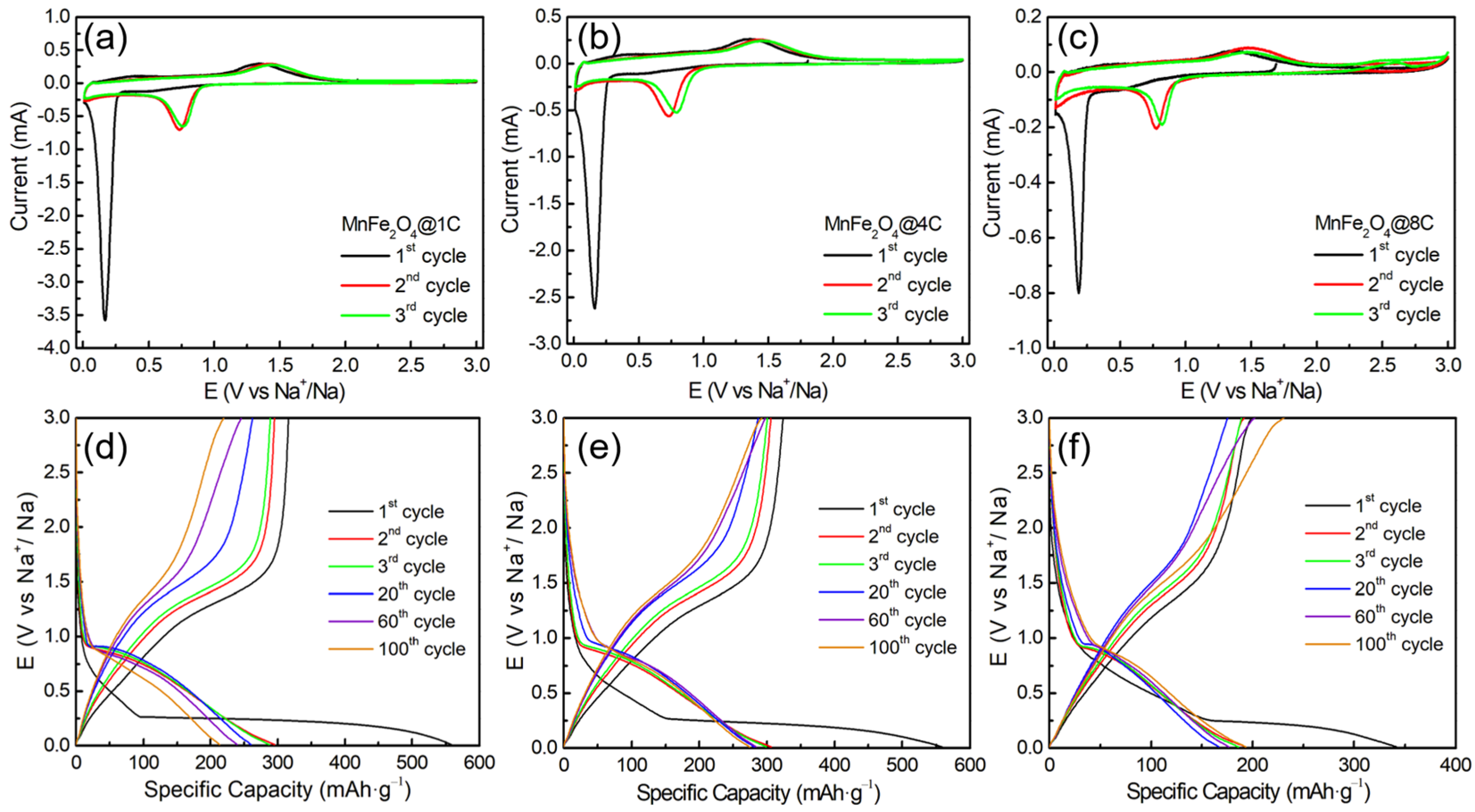
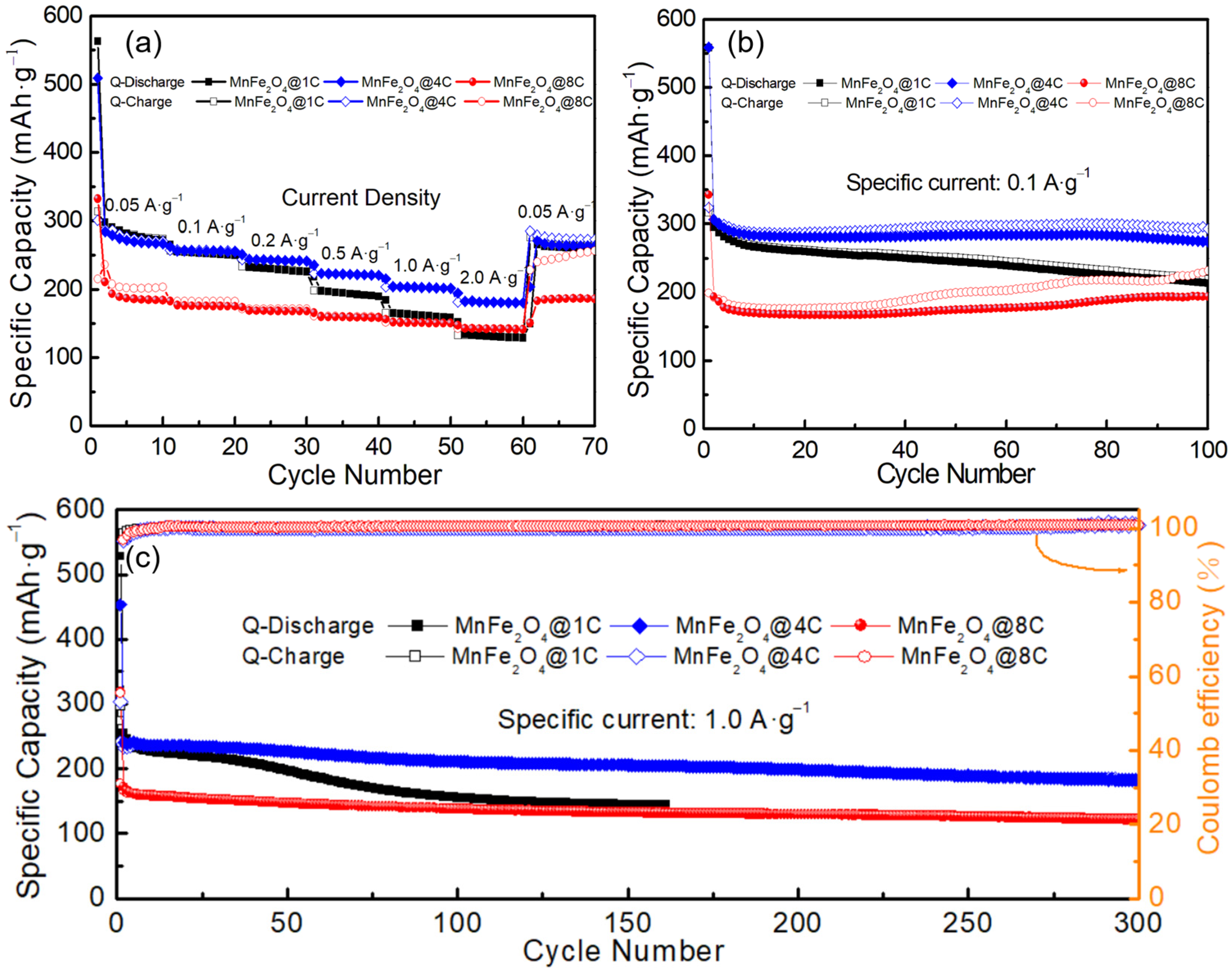
2.2. Sodium-Ion Storage Performance of the MnFe2O4@xC Nanocomposites

The Na+ storage performance of the three MnFe2O4@xC nanocomposites was evaluated, as presented in Figure 3 and Figure 4. As shown in Figure 3a–c, the CV curves of the three materials show similar features. During the first cathodic scan, a sharp cathodic peak at ~0.17 V is observed before disappearing in the subsequent cycle, which is mainly attributed to irreversible electrochemical processes such as the transformation of MnFe2O4 to metallic Mn and Fe [29] and the formation of SEI, as represented in Equation (1). The anodic peak around 1.34 V is assigned to the oxidation of Mn and Fe, leading to the formation of MnO and Fe2O3, respectively, as indicated in Equation (2).
MnFe2O4 + 8Na+ + 8e → Mn + 2Fe + 4Na2O,
Mn + 2Fe + 4Na2O → MnO + Fe2O3 + 8Na+ + 8e,
In the second and third cycles, a cathodic peak shows up at ~0.76 V, indicating the reversible reduction reactions of MnO to Mn and Fe2O3 to Fe (Equations (3) and (4)) [30,31]. From the second cycle onwards, it is noted that the majority of the CV curves overlap, indicating the favorable reversibility of the electrochemical reactions, as described in Equations (5) and (6) [13,32,33,34].
MnO + 2Na+ + 2e → Mn + Na2O,
Fe2O3 + 6Na+ + 6e → 2Fe + 3Na2O,
Overall: MnO + Fe2O3 + 8Na+ + 8e ↔ Mn + 2Fe + 4Na2O,
xC+ Na+ +e ↔ NaCx,
Figure 3d–f show the galvanostatic discharge–charge profiles of MnFe2O4@1C, MnFe2O4@4C, and MnFe2O4@8C at 0.1 A·g−1 in Na half cells. In the first discharge–charge profiles, all samples exhibit irreversible capacity loss, which is attributed to the formation of an SEI layer and the irreversible transformation of MnFe2O4. The first discharge capacities of MnFe2O4@1C, MnFe2O4@4C, and MnFe2O4@8C are 558, 559, and 343 mAh·g−1, respectively. Starting from the second cycle, the discharge–charge capacities of MnFe2O4@1C, MnFe2O4@4C, and MnFe2O4@8C show good reversibility, with values of 295/295, 308/307, and 195/194 mAh·g−1, respectively. MnFe2O4@4C shows a notable improvement in specific capacity compared to MnFe2O4@1C and MnFe2O4@8C. With increasing cycle number (1st to 100th cycle), the capacity of MnFe2O4@1C decays, while that of MnFe2O4@4C and MnFe2O4@8C remains constant.
The rate capabilities of MnFe2O4@1C, MnFe2O4@4C, and MnFe2O4@8C in Na half cells were tested, as shown in Figure 4a. With the specific current increasing from 0.05 A g−1 through 0.1, 0.2, 0.5, and 1.0 to 2.0 A g−1 (40 folds), the specific capacity retentions of MnFe2O4@1C, MnFe2O4@4C, and MnFe2O4@8C are 44%, 65%, and 63% (from 295, 286, and 210 mAh·g−1 to 131, 182, and 132 mAh·g−1, respectively). MnFe2O4@4C and MnFe2O4@8C show better rate capabilities than MnFe2O4@1C. Further research was conducted on the cycling stability of MnFe2O4@xC electrodes in Na half cells. Figure 4b depicts the long-term cycling performance of MnFe2O4@1C, MnFe2O4@4C, and MnFe2O4@8C electrodes at 0.1 A·g−1. The results indicate that after 100 cycles, the three electrodes achieved discharge capacities of 220, 274, and 193 mAh·g−1 from the initial discharge capacities of 308, 295, and 195 mAh·g−1, with capacity retentions of 71%, 93%, and 99%, respectively. At a specific current of 1.0 A·g−1 (Figure 4c), the initial capacities of the MnFe2O4@4C and MnFe2O4@8C electrodes are 250 and 166 mAh·g−1, decaying to 183 and 129 mAh·g−1 after 300 cycles, indicating capacity retentions of around 73% and 78%, respectively. The MnFe2O4@1C electrode shows inferior cycling stability relative to the other two electrodes. In summary, MnFe2O4@1C and MnFe2O4@4C show higher specific capacity than MnFe2O4@8C, while MnFe2O4@4C and MnFe2O4@8C show superior rate capability and cycling stability relative to MnFe2O4@1C. Comprehensively considering the specific capacity, rate capability, and cycling stability, MnFe2O4@4C achieves optimal electrochemical battery performance. A comparison of the SIB anode performance of the MnFe2O4@4C nanocomposite with other TMOs is shown in Table 1, revealing the superior electrochemical performance of our material.

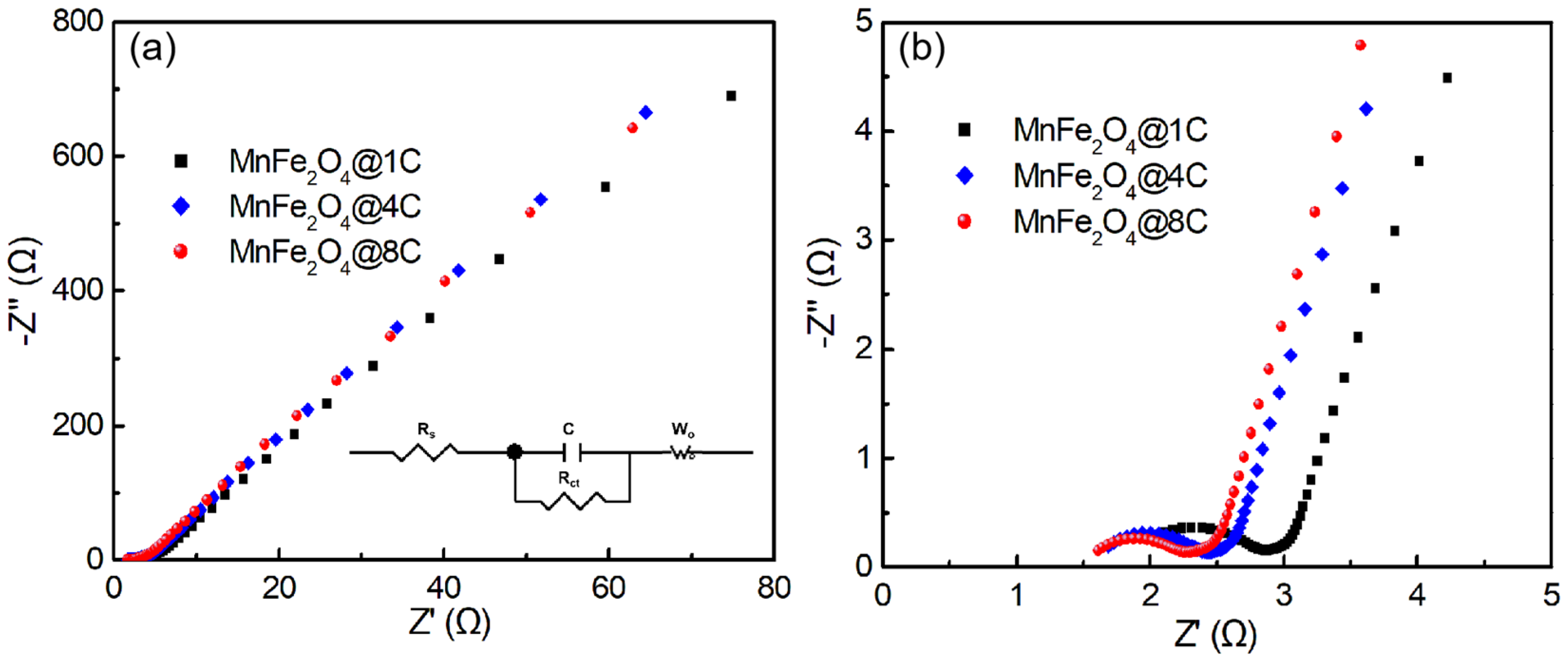
2.3. Exploring the Origin of the Improvement in the Sodium-Ion Storage of the MnFe2O4@xC Nanocomposites

Figure 5a illustrates the results of an EIS test on the three MnFe2O4@xC nanocomposites. The Nyquist curves of the three materials exhibit similar trends, comprising a semicircle in the high-frequency region and an inclined straight line in the low-frequency region (Figure 5b). The cell resistances (Rs, calculated from the intercept of the X-axis) for the MnFe2O4@1C, MnFe2O4@4C, and MnFe2O4@8C Na half cells are 1.86, 1.59, and 1.54 Ω, respectively. The diameters of the semicircles represent the charge transfer resistance (Rct) coming from the electrode material/electrolyte interface reaction, which are 0.84, 0.70, and 0.62 Ω for the MnFe2O4@1C, MnFe2O4@4C, and MnFe2O4@8C nanocomposite electrodes, respectively. The Rct increases gradually with the increase in the thickness (content) of the carbon shell in the core–shell nanostructure due to the good electric conductivity of the carbon material, which improves the electric conductivity of the MnFe2O4@xC core–shell nanocomposites as a whole. Good electric conductivity leads to good rate capability. Moreover, as observed in Figure 1 and Figure 2, the particle connectivity of MnFe2O4@xC nanocomposites increases with the increase in carbon shell thickness (content), which leads to enhanced rate capability and cycling stability. Therefore, MnFe2O4@4C and MnFe2O4@8C show superior rate capability and cycling stability relative to MnFe2O4@1C. Nevertheless, a thick carbon shell results in a small ratio of active MnFe2O4 core material (the specific capacity was calculated based on the mass of the whole MnFe2O4@4C nanocomposite), leading to a decreased specific capacity, which explains the lower specific capacity of MnFe2O4@8C relative to MnFe2O4@1C and MnFe2O4@4C. In summary, the use of MnFe2O4@4C with an appropriate carbon shell thickness (content) leads to optimal battery performance.
To systematically investigate the electrochemical reaction kinetics of MnFe2O4@4C as an anodic electrode material for Na half cells, the corresponding CV curves were tested, with the scan rate increasing from 0.2 to 1.6 mV·s−1 (Figure 6a). The CV curves of MnFe2O4@4C at different scanning rates exhibit similar shapes, indicating that the material has low polarization and good electrochemical reaction kinetics. Under different scanning rates (v), the capacitance behavior or diffusion behavior of the electrode is obtained by deducing the current (i) according to the following formula (Equations (7) and (8)) [43,44,45]:
i = avb, or
log i = b log v + log a,
where a is a constant and b represents the capacitance ratio, which can be determined by the slope of the logarithmic curve (log (i) vs. log (v)). A value of b = 0.5 indicates a diffusion-controlled behavior, while a value of b = 1.0 signifies a pseudocapacitance-controlled contribution. In Figure 6b, the slope of the redox process is depicted, with the b values of cathodic and anodic currents being 0.86 and 0.88, respectively. This suggests that the sodium storage behavior in MnFe2O4@4C is primarily influenced by pseudocapacitance. Additionally, we consider Equation (9) [46],
i (V) = k1v + k2v1/2,
where the current (i) at a fixed potential (V) in CV can be divided into two parts, namely capacitance behavior (k1v) and diffusion control (k2v1/2). The capacitive contribution of the MnFe2O4@4C half cell at 1.0 mV·s−1 is shown in Figure 6c, which is measured to be 95.6% of the total contribution. The respective contributions of capacitance behavior and diffusion control at different scan rates are depicted in Figure 6d. The contribution of capacitance behavior increases as the scan rate rises, indicating that the pseudocapacitance process in the MnFe2O4@4C Na half cell becomes more prominent at higher scan rates, demonstrating faster kinetics. At a scanning rate of 1.6 mV·s−1, a capacitance contribution of 97.5% is achieved. Even at a low rate of 0.2 mV·s−1, MnFe2O4@4C still significantly contributes to the capacitance behavior (92.2%). MnFe2O4@1C and MnFe2O4@8C show similar electrochemical reaction kinetics to those of MnFe2O4@4C, with the b values of cathodic and anodic currents of the MnFe2O4@1C electrode of 0.85 and 0.84, respectively, while those of the MnFe2O4@8C electrode are 0.86 and 0.90, respectively (Figure S3).

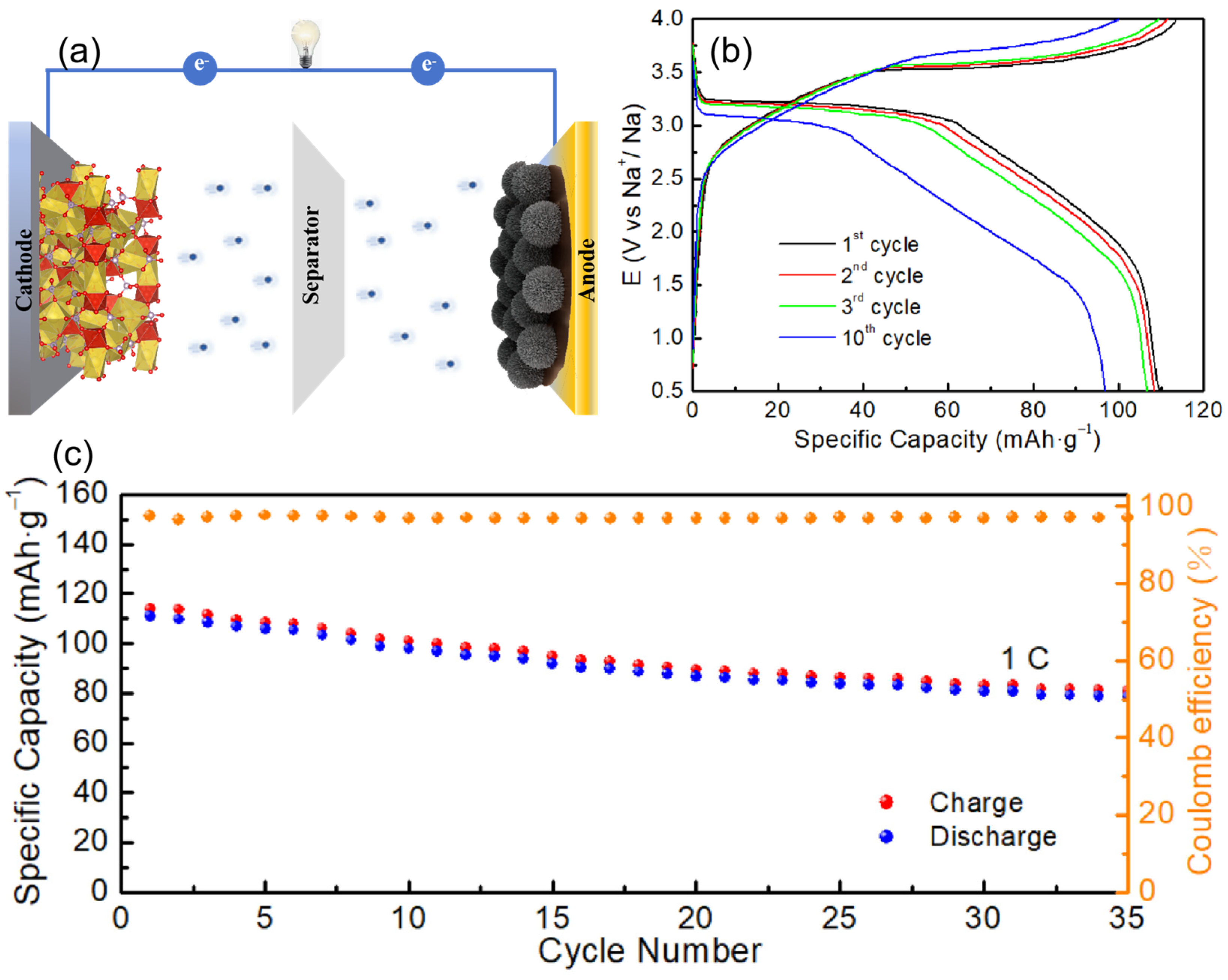
2.4. Full-Cell Performance

To further assess the practical usability of MnFe2O4@4C in SIBs, full-cell configurations were assembled, with Na3V2(PO4)3 (NVP) serving as the cathode and MnFe2O4@4C as the anode (Figure 7a). The charge–discharge profiles of the NVP//MnFe2O4@4C full SIB at 1 C-rate (1 C-rate = 120 mA·g−1) within the voltage range of 0.5–4.0 V are presented in Figure 7b. In the initial cycle, NVP//MnFe2O4@4C SIB demonstrates a specific capacity of 111 mAh·g−1 at 1C. As illustrated in Figure 7c, the full cell exhibits favorable electrochemical performance, with a stable and reversible capacity of 78.5 mAh·g−1 over 35 cycles, and maintains a Coulombic efficiency of over 97% throughout the cycling process.

3. Materials and Methods

3.1. Synthesis of the MnFe2O4 Spherical Nanoparticles

The MnFe2O4 spherical nanoparticles were synthesized using a hydrothermal method based on the methods reported in [47], with some modifications. Initially, MnCl2·4H2O (0.396 g, 2 mmol) and FeCl3·6H2O (1.081 g, 4 mmol) were added to 80 mL of ethylene glycol and stirred to form a solution. Subsequently, NaAc (7.2 g) and polyethylene glycol (2.0 g, M = 20,000) were added. After stirring for 12 h, the resulting homogeneous solution was transferred into a 100 mL autoclave with a Teflon® lining and heated at 200 °C for 10 h. After being cooled to room temperature, the resulting brown precipitate was collected via centrifugation at 10,000 rpm, washed several times with ultrapure water and absolute ethanol, and dried at 60 °C for 6 h.

3.2. Synthesis of the MnFe2O4@xC Spherical Nanocomposites

The carbon shell was coated onto the MnFe2O4 core to form MnFe2O4@xC core–shell nanocomposites by pyrolysis of PVDF [48,49]. In general, 16.0 mg of PVDF was dissolved in a beaker containing 280.0 mg of N-methylpyrrolidone (NMP) with a PVDF mass ratio of 6%. Then, 100 mg of MnFe2O4 spherical nanoparticles was added to the above solution and stirred for 24 h. The mixture was then dried at 120 °C for 24 h and moved to a combustion boat, where it was crystallized and carbonized in an Argon flow at 700 °C for 2 h at a ramp rate of 2 °C/min. The product obtained after natural cooling is denoted as MnFe2O4@1C. Similarly, after increasing the mass of PVDF to 64.0 and 128.0 mg for pyrolysis, the obtained products were referred to as MnFe2O4@4C and MnFe2O4@8C, respectively.
Comprehensive details regarding material characterization, electrochemical measurements, and kinetics analysis can be found in the Supplementary Materials.

4. Conclusions

In this work, MnFe2O4@xC nanocomposites were successfully synthesized by a hydrothermal method with MnFe2O4 inner cores, and the thicknesses of the carbon shells were tuned by pyrolysis of PVDF. The electrochemical performance of MnFe2O4@xC nanocomposites as anode materials for SIBs was evaluated. Compared to MnFe2O4@1C and MnFe2O4@8C, MnFe2O4@4C nanocomposite achieves optimal electrochemical performance. It releases a reversible specific capacity of around 308 mAh·g−1 at 0.1 A·g−1 and 73% capacity retention after 100 cycles and 250 mAh·g−1 at 1.0 A g−1 with 73% capacity retention after 300 cycles in a half cell and of around 111 mAh·g−1 at 1.0 C coupled with a Na3V2(PO4)3 (NVP) cathode in a full SIB cell. TEM, EIS, and kinetic analysis show that the optimal electrochemical performance of MnFe2O4@4C is due to its appropriate carbon shell thickness (content) of 20–30 nm (12.89% mass ratio), which leads to the optimal electric conductivity, particle connectivity, and kinetics of the electrode material, as well as enhanced specific capacity, rate capability, and cycling stability.

Supplementary Materials

The following supporting information can be downloaded at: https://www.mdpi.com/article/10.3390/molecules29163912/s1, Figure S1: SEM images of MnFe2O4 spherical nanoparticles; Figure S2: TGA curves recorded for MnFe2O4@1C, MnFe2O4@4C, and MnFe2O4@8C nanocomposites under Ar flow; Figure S3: CVs at various scan rates and the calculated b values of MnFe2O4@1C and MnFe2O4@8C nanocomposite electrodes.

Author Contributions

Conceptualization, X.-M.L.; methodology, B.-T.N. and X.-M.L.; resources, X.-M.L.; data curation, S.-W.L., B.-T.N., B.-L.L. and Y.-T.L.; writing−original draft preparation, B.-T.N. and X.-M.L.; writing−review and editing, X.-P.C., H.-X.G., Y.-X.C. and X.-M.L. All authors have read and agreed to the published version of the manuscript.

Funding

This research was funded by the National Natural Science Foundation of China (No. 22272069) and the Natural Science Foundation of Fujian Province (No. 2021J01988; 2022J05173 and 2023H0046).

Institutional Review Board Statement

Not applicable.

Informed Consent Statement

Not applicable.

Data Availability Statement

The data presented in this study are available upon request from the corresponding author.

Conflicts of Interest

The authors declare no conflicts of interest.

References

  1. Gao, Y.; Zhang, H.; Peng, J.; Li, L.; Xiao, Y.; Li, L.; Liu, Y.; Qiao, Y.; Chou, S.-L. A 30-year overview of sodium-ion batteries. Carbon Energy 2024, 6, e464. [Google Scholar] [CrossRef]
  2. Jiang, Y.; Zhang, Z.; Liao, H.; Zheng, Y.; Fu, X.; Lu, J.; Cheng, S.; Gao, Y. Progress and Prospect of Bimetallic Oxides for Sodium-Ion Batteries: Synthesis, Mechanism, and Optimization Strategy. ACS Nano 2024, 18, 7796–7824. [Google Scholar] [CrossRef] [PubMed]
  3. Cheng, D.; Ye, L.; Wei, A.; Xu, G.; Cao, Z.; Zhu, P.; Chen, Y. Constructing SnS/Fe2O3 heterostructure anchored on few-layered graphene as an ion-adsorption/diffusion enhancer for ultrafast and cycle-stable sodium storage. Chem. Eng. J. 2023, 457, 141243. [Google Scholar] [CrossRef]
  4. Huang, Z.-X.; Gu, Z.-Y.; Heng, Y.-L.; Ang, E.-H.; Geng, H.-B.; Wu, X.-L. Advanced layered oxide cathodes for sodium/potassium-ion batteries: Development, challenges, and prospects. Chem. Eng. J. 2023, 452, 139438. [Google Scholar] [CrossRef]
  5. Deng, X.; Chen, Z.; Cao, Y. Transition metal oxides based on conversion reaction for sodium-ion battery anodes. Mater. Today Chem. 2018, 9, 114–132. [Google Scholar] [CrossRef]
  6. Liu, X.; Cheng, Q.; Zhong, W.; Deng, Q.; Yang, C.; Liu, Y.; Hu, J.; Yang, C. Construction of defective MoxW1-xS2/Cu7.2S4 polyhedral heterostructures for fast sodium storage. Chem. Eng. J. 2023, 451, 138645. [Google Scholar] [CrossRef]
  7. Liu, G.; Yang, Y.; Lu, X.; Qi, F.; Liang, Y.; Trukhanov, A.; Wu, Y.; Sun, Z.; Lu, X. Fully Active Bimetallic Phosphide Zn0.5Ge0.5P: A Novel High-Performance Anode for Na-Ion Batteries Coupled with Diglyme-Based Electrolyte. ACS Appl. Mater. Interfaces 2022, 14, 31803–31813. [Google Scholar] [CrossRef]
  8. Liu, Z.; Wang, R.; Zhang, P.; Dun, C.; Urban, J.J.; Yang, S.; Wang, T.; Ma, Y.; Zhong, Y.; He, J.; et al. Are sodiation/de-sodiation reactions reversible in two-dimensional metallic NbSe2? Energy Environ. Sci. 2024, 17, 2173–2181. [Google Scholar] [CrossRef]
  9. Jin, Q.; Wang, K.; Feng, P.; Zhang, Z.; Cheng, S.; Jiang, K. Surface-dominated storage of heteroatoms-doping hard carbon for sodium-ion batteries. Energy Storage Mater. 2020, 27, 43–50. [Google Scholar] [CrossRef]
  10. Guo, S.; Li, H.; Lu, Y.; Liu, Z.; Hu, X. Lattice softening enables highly reversible sodium storage in anti-pulverization Bi–Sb alloy/carbon nanofibers. Energy Storage Mater. 2020, 27, 270–278. [Google Scholar] [CrossRef]
  11. Huang, J.; Callender, K.I.E.; Qin, K.; Girgis, M.; Paige, M.; Yang, Z.; Clayborne, A.Z.; Luo, C. Halogenated Carboxylates as Organic Anodes for Stable and Sustainable Sodium-Ion Batteries. ACS Appl. Mater. Interfaces 2022, 14, 40784–40792. [Google Scholar] [CrossRef] [PubMed]
  12. Qi, S.; Xu, B.; Tiong, V.T.; Hu, J.; Ma, J. Progress on iron oxides and chalcogenides as anodes for sodium-ion batteries. Chem. Eng. J. 2020, 379, 122261. [Google Scholar] [CrossRef]
  13. Liu, Y.; Zhang, N.; Yu, C.; Jiao, L.; Chen, J. MnFe2O4@C Nanofibers as High-Performance Anode for Sodium-Ion Batteries. Nano Lett. 2016, 16, 3321–3328. [Google Scholar] [CrossRef] [PubMed]
  14. Chandran, M.K.N.; Babu, G.N.S.; Sathish, M. CuMn2O4 anchored on graphene sheets as high-performance electrodes for sodium-ion batteries. J. Energy Storage 2023, 65, 107346. [Google Scholar] [CrossRef]
  15. He, Q.; Gu, S.; Wu, T.; Zhang, S.; Ao, X.; Yang, J.; Wen, Z. Self-supported mesoporous FeCo2O4 nanosheets as high capacity anode material for sodium-ion battery. Chem. Eng. J. 2017, 330, 764–773. [Google Scholar] [CrossRef]
  16. Maggay, I.V.B.; De Juan, L.M.Z.; Lu, J.-S.; Nguyen, M.T.; Yonezawa, T.; Chan, T.-S.; Liu, W.-R. Electrochemical properties of novel FeV2O4 as an anode for Na-ion batteries. Sci. Rep. 2018, 8, 8839. [Google Scholar] [CrossRef]
  17. Yang, X.-T.; Huang, T.-Y.; Wang, Y.-H.; Dong, J.-C.; Wei, Q.-L.; Zhang, H.; Lin, X.-M.; Li, J.-F. Understanding the origin of the improved sodium ion storage performance of the transition metal oxide@carbon nanocomposite anodes. J. Chem. Phys. 2023, 158, 174708. [Google Scholar] [CrossRef] [PubMed]
  18. Yang, X.; Wang, P.; Tang, Y.; Peng, C.; Lai, Y.; Li, J.; Zhang, Z. Bimetallic ZIF–derived polyhedron ZnCo2O4 anchored on the reduced graphene oxide as an anode for sodium-ion battery. Ionics 2019, 25, 2945–2950. [Google Scholar] [CrossRef]
  19. Chandra Sekhar, B.; Packiyalakshmi, P.; Kalaiselvi, N. Custom-designed ZnMn2O4/nitrogen-doped graphene composite anode validated for sodium ion battery application. RSC Adv. 2017, 7, 20057–20061. [Google Scholar] [CrossRef]
  20. Ghosh, S.; de Donder, T.; Gunnarsson, K.; Kumar, V.K.; Martha, S.K.; Svedlindh, P.; Kessler, V.G.; Seisenbaeva, G.A.; Pol, V.G. Investigating the stable operating voltage for the MnFe2O4 Li-ion battery anode. Sustain. Energy Fuels 2021, 5, 1904–1913. [Google Scholar] [CrossRef]
  21. Du, Y.; Liu, C.; Sun, S.; Wu, S. Core-shell MnO@MnFe2O4 Anchored by Reduced Graphene Oxide as Anode of Li-Ion Batteries Operated under Ultrawide Temperature Range. ChemElectroChem 2017, 4, 2500–2506. [Google Scholar] [CrossRef]
  22. Man, Y.; Sun, J.; Zhao, X.; Duan, L.; Fei, Y.; Bao, J.; Mo, X.; Zhou, X. An ultrastable sodium-ion battery anode enabled by carbon-coated porous NaTi2(PO4)3 olive-like nanospheres. J. Colloid Interface Sci. 2023, 635, 417–426. [Google Scholar] [CrossRef] [PubMed]
  23. Yu, Z.; Wang, Q.; Zhu, K.; Wang, G.; Cao, D.; Yan, J. N-doped carbon coated MoO3/MoS2 integrated MXene nanosheets with ultra-long cycle stability for sodium-ion batteries. Appl. Surf. Sci. 2024, 652, 159294. [Google Scholar] [CrossRef]
  24. Deng, Z.; He, M.; Feng, Y.; Xiong, D. A fluorine-doped MnFe2O4 nanorod/carbon composite as an anode material for high-performance lithium-ion batteries. Int. J. Electrochem. Sci. 2020, 15, 4203–4217. [Google Scholar] [CrossRef]
  25. Han, J.; Chen, Y.; Xiang, X.; Wang, T.; Shen, J.; Zhang, N.; Liang, C.; Liu, X.; Ma, X. A Comparative Analysis of the Antibacterial Spectrum of Ultrasmall Manganese Ferrite Nanozymes with Varied Surface Modifications. ACS Appl. Mater. Interfaces 2024, 16, 14385–14404. [Google Scholar] [CrossRef] [PubMed]
  26. Bhosale, R.; Bhosale, S.; Sankannavar, R.; Chavan, V.; Jambhale, C.; Kim, H.; Kolekar, S. Bimetallic MnFe2-MOF and Its Derived MnFe2O4 Nanostructures for Supercapacitive Applications. ACS Appl. Nano Mater. 2024, 7, 4078–4091. [Google Scholar] [CrossRef]
  27. Dieu Cam, N.T.; Pham, H.-D.; Pham, T.-D.; Thu Phuong, T.T.; Van Hoang, C.; Thanh Tung, M.H.; Trung, N.T.; Huong, N.T.; Thu Hien, T.T. Novel photocatalytic performance of magnetically recoverable MnFe2O4/BiVO4 for polluted antibiotics degradation. Ceram. Int. 2021, 47, 1686–1692. [Google Scholar] [CrossRef]
  28. Qin, H.; Yang, Y.; Shi, W.; She, Y. Heterogeneous Fenton degradation of ofloxacin catalyzed by magnetic nanostructured MnFe2O4 with different morphologies. Environ. Sci. Pollut. Res. 2021, 28, 26558–26570. [Google Scholar] [CrossRef] [PubMed]
  29. Liu, S.; Xie, J.; Su, Q.; Du, G.; Zhang, S.; Cao, G.; Zhu, T.; Zhao, X. Understanding Li-storage mechanism and performance of MnFe2O4 by in situ TEM observation on its electrochemical process in nano lithium battery. Nano Energy 2014, 8, 84–94. [Google Scholar] [CrossRef]
  30. Liu, B.; Hu, X.; Xu, H.; Luo, W.; Sun, Y.; Huang, Y. Encapsulation of MnO Nanocrystals in Electrospun Carbon Nanofibers as High-Performance Anode Materials for Lithium-Ion Batteries. Sci. Rep. 2014, 4, 4229. [Google Scholar] [CrossRef]
  31. Cao, Y.; Xiao, L.; Sushko, M.L.; Wang, W.; Schwenzer, B.; Xiao, J.; Nie, Z.; Saraf, L.V.; Yang, Z.; Liu, J. Sodium Ion Insertion in Hollow Carbon Nanowires for Battery Applications. Nano Lett. 2012, 12, 3783–3787. [Google Scholar] [CrossRef] [PubMed]
  32. Chen, J.; Xu, L.; Li, W.; Gou, X. α-Fe2O3 Nanotubes in Gas Sensor and Lithium-Ion Battery Applications. Adv. Mater. 2005, 17, 582–586. [Google Scholar] [CrossRef]
  33. Kim, H.; Lee, J.-W.; Byun, D.; Choi, W. Coaxial-nanostructured MnFe2O4 nanoparticles on polydopamine-coated MWCNT for anode materials in rechargeable batteries. Nanoscale 2018, 10, 18949–18960. [Google Scholar] [CrossRef] [PubMed]
  34. Zhang, L.; Bai, J.; Gao, F.; Li, S.; Liu, Y.; Guo, S. Tailoring of hierarchical MnMoO4/C nanocauliflowers for high-performance lithium/sodium ion half/full batteries. J. Alloys Compd. 2022, 906, 164394. [Google Scholar] [CrossRef]
  35. Vincent, M.; Kumar, S.S.; Kowalski, D. Pseudocapacitive vs. diffusion controlled charge storage in Fe2O3 nanosheet Na-ion battery. Electrochim. Acta 2023, 469, 143161. [Google Scholar] [CrossRef]
  36. Jiang, J.; Ma, C.; Ma, T.; Zhu, J.; Liu, J.; Yang, G.; Yang, Y. A novel CoO hierarchical morphologies on carbon nanofiber for improved reversibility as binder-free anodes in lithium/sodium ion batteries. J. Alloys Compd. 2019, 794, 385–395. [Google Scholar] [CrossRef]
  37. Yusoff, N.F.M.; Idris, N.H.; Din, M.F.M.; Majid, S.R.; Harun, N.A. Three-dimensional network of Mn3O4/reduced graphene oxide aerogel with improved electrochemical performances of sodium-ion batteries. J. Mater. Sci. 2023, 58, 8924–8939. [Google Scholar] [CrossRef]
  38. Zhang, S.; Ai, Y.; Wu, S.-C.; Liao, H.-J.; Su, T.-Y.; Chen, J.-H.; Wang, C.-H.; Lee, L.; Chen, Y.-Z.; Xu, B.; et al. 3D CoMoSe4 Nanosheet Arrays Converted Directly from Hydrothermally Processed CoMoO4 Nanosheet Arrays by Plasma-Assisted Selenization Process Toward Excellent Anode Material in Sodium-Ion Battery. Nanoscale Res. Lett. 2019, 14, 213. [Google Scholar] [CrossRef] [PubMed]
  39. Zhao, Y.; Zhang, W.-B.; Li, Y.; Liu, H.-B.; Zhao, Z.-Y.; Li, K.; Wang, Y.-K.; Li, X.; Ma, T.-L.; Kong, L.-B. Construction of ultra-stable and high-performance sodium-ion hybrid capacitors via CoMoO4 nanorods anode. J. Power Sources 2024, 592, 233791. [Google Scholar] [CrossRef]
  40. Yu, K.; Chang, M.; Yue, L.; Wang, X.; Chen, J.; Liang, C. Submicron cubic ZnMn2O4 loaded on biomass porous carbon used as high-performance bifunctional electrode for lithium-ion and sodium-ion batteries. J. Alloys Compd. 2024, 971, 172769. [Google Scholar] [CrossRef]
  41. Zhang, Z.; Zhou, J.; Zhou, X.; Wang, C.; Pan, Z.; Xu, X.; Liu, X.; Wang, Z.; Wu, Y.; Jiang, S.; et al. Graphene oxide-supported MnV2O6 nanoribbons with enhanced electrochemical performance for sodium-ion batteries. J. Power Sources 2024, 597, 234117. [Google Scholar] [CrossRef]
  42. Huang, X.; Zhang, W.; Zhou, C.; Yang, L.; Wang, H.; Gao, Q.; Zhu, M. N-doped carbon encapsulated CoMoO4 nanorods as long-cycle life anode for sodium-ion batteries. J. Colloid Interface Sci. 2020, 576, 176–185. [Google Scholar] [CrossRef] [PubMed]
  43. Wei, Q.; Chang, X.; Butts, D.; DeBlock, R.; Lan, K.; Li, J.; Chao, D.; Peng, D.-L.; Dunn, B. Surface-redox sodium-ion storage in anatase titanium oxide. Nat. Commun. 2023, 14, 7. [Google Scholar] [CrossRef] [PubMed]
  44. Ma, Y.; Ma, Y.; Kim, G.T.; Diemant, T.; Behm, R.J.; Geiger, D.; Kaiser, U.; Varzi, A.; Passerini, S. Superior Lithium Storage Capacity of α-MnS Nanoparticles Embedded in S-Doped Carbonaceous Mesoporous Frameworks. Adv. Energy Mater. 2019, 9, 1902077. [Google Scholar] [CrossRef]
  45. An, C.; Yuan, Y.; Zhang, B.; Tang, L.; Xiao, B.; He, Z.; Zheng, J.; Lu, J. Graphene Wrapped FeSe2 Nano-Microspheres with High Pseudocapacitive Contribution for Enhanced Na-Ion Storage. Adv. Energy Mater. 2019, 9, 1900356. [Google Scholar] [CrossRef]
  46. Chen, X.; Feng, X.; Ren, B.; Jiang, L.; Shu, H.; Yang, X.; Chen, Z.; Sun, X.; Liu, E.; Gao, P. High Rate and Long Lifespan Sodium-Organic Batteries Using Pseudocapacitive Porphyrin Complexes-Based Cathode. Nano-Micro Lett. 2021, 13, 71. [Google Scholar] [CrossRef]
  47. Wang, G.; Li, X.; Ma, Y.; He, Y.; Hou, J.; Che, H.; Zhang, X.; Han, S.; Wang, Z.; Li, Z.; et al. Fabrication, characterisation and magneto-responsive performance of manganese ferrite nanospheres for fast separation of oil slicks from water surfaces. Ceram. Int. 2023, 49, 32962–32970. [Google Scholar] [CrossRef]
  48. Xu, Y.; Yin, G.; Ma, Y.; Zuo, P.; Cheng, X. Nanosized core/shell silicon@carbon anode material for lithium ion batteries with polyvinylidene fluoride as carbon source. J. Mater. Chem. 2010, 20, 3216–3220. [Google Scholar] [CrossRef]
  49. Hong, S.-M.; Etacheri, V.; Hong, C.N.; Choi, S.W.; Lee, K.B.; Pol, V.G. Enhanced Lithium- and Sodium-Ion Storage in an Interconnected Carbon Network Comprising Electronegative Fluorine. ACS Appl. Mater. Interfaces 2017, 9, 18790–18798. [Google Scholar] [CrossRef]
Figure 1. (a) Powder XRD patterns of MnFe2O4 and MnFe2O4@1C. (b) Raman spectra of MnFe2O4@1C, MnFe2O4@4C, and MnFe2O4@8C nanocomposites. (c) SEM images of MnFe2O4@1C nanocomposite. (d,e) TEM images of MnFe2O4@1C nanocomposite. (fi) Elemental mapping images of MnFe2O4@1C.
Molecules 29 03912 g001
Figure 2. (a,b) HRTEM images of MnFe2O4@4C. (c,d) TEM images of MnFe2O4@8C.
Molecules 29 03912 g002
Figure 3. Initial three CV curves of (a) MnFe2O4@1C, (b) MnFe2O4@4C, and (c) MnFe2O4@8C. Galvanostatic discharge–charge profiles of (d) MnFe2O4@1C, (e) MnFe2O4@4C, and (f) MnFe2O4@8C at 0.1 A·g−1 in a Na half cell (0.01–3.0 V).
Molecules 29 03912 g003
Figure 4. Rate capability (a) and cycling stability of MnFe2O4@1C, MnFe2O4O@4C, and MnFe2O4@8C at specific currents of (b) 0.1 A·g−1 and (c) 1.0 A·g−1 in a Na half–cell.
Molecules 29 03912 g004
Figure 5. (a) AC impedance measurements of MnFe2O4@1C, MnFe2O4@4C, and MnFe2O4@8C nanocomposite electrodes. The insert in (a) is the equivalent circuit diagram. (b) The zoomed−in area of the plots in the high-frequency region of (a).
Molecules 29 03912 g005
Figure 6. (a) CVs at various scan rates. (b) Calculated b values. (c) Capacitive contribution at a scan rate of 1.0 mV·s−1. (d) The ratio of capacitive contribution of the MnFe2O4@4C anode at various scan rates.
Molecules 29 03912 g006
Figure 7. NVP//MnFe2O4@4C full cell: (a) illustrative diagram; (b) voltage-versus-capacity profiles at 1.0 C during cycling at different cycle numbers; (c) cycling performance at 1.0 C.
Molecules 29 03912 g007
Table 1. Comparison of the SIB performance of the MnFe2O4@4C nanocomposite with other TMOs.
MaterialsVoltage Range
(V vs. Na+/Na)
Specific Capacity
(mAh·g−1)/Cycles/
Current Density (A·g−1)
Rate Performance (mAh·g−1)/Current Density (A·g−1)Ref.
CuMn2O4/
graphene
0.01–3.0313/50th/0.1145/2.0[14]
Fe2O3-600 nanosheets0.01–3.0~100/250th/0.5100/0.5[35]
CNF/CoO-40.01–3.0138/100th/0.1[36]
Mn3O4/rGO
aerogels
0.01–3.0283/100th/0.1121/1.0[37]
CoMoO4@C0.5–3.046/50th/0.545/2.0[38]
CoMoO4
nanorod
0.01–3.0200/60th/0.1160/0.5[39]
ZnMn2O4/jute porous carbon0.01–3.0392.4/200th/0.1244.7/1.0[40]
MnV2O6/GO0.01–3.0323.8/100th/0.1213.8/2.0[41]
CoMoO4@NC0.01–3.0281/80th/0.1221/2.0[42]
MnFe2O4@4C0.01–3.0250/100th/0.1182/2.0This
work
Disclaimer/Publisher’s Note: The statements, opinions and data contained in all publications are solely those of the individual author(s) and contributor(s) and not of MDPI and/or the editor(s). MDPI and/or the editor(s) disclaim responsibility for any injury to people or property resulting from any ideas, methods, instructions or products referred to in the content.

