Article

Dry Carbonate Sorbents for CO2 Capture from Flue Gases: Role of Support in Adsorption Efficiency and Thermal Stability

by
Bolatbek Khussain
1,
Alexandr Sass
1,*,
Alexandr Brodskiy
1,*,
Murat Zhurinov
1,
Ivan Torlopov
1,
Kenzhegul Rakhmetova
1,
Daulet Zhumadullaev
1,
Yerzhan Boleubayev
1,
Atabek Khussain
1,
Abzal Kenessary
2,
Adel Sarsenova
2 and
Tumen Darzhokov
2
1
D.V. Sokolsky Institute of Fuel, Catalysis and Electrochemistry, 142, Kunaev Str., Almaty 050010, Kazakhstan
2
Kazakh Institute of Oil and Gas, 506/99, Seifullin Ave., Almaty 050000, Kazakhstan
*
Authors to whom correspondence should be addressed.
Molecules 2025, 30(13), 2859; https://doi.org/10.3390/molecules30132859
Submission received: 15 May 2025 / Revised: 16 June 2025 / Accepted: 2 July 2025 / Published: 4 July 2025
(This article belongs to the Special Issue Novel Adsorbents for Environmental Pollutants' Removal)

Abstract

This study presents the results of an investigation of carbonate-containing sorbents for CO2 capture with natural support materials—kaolin and calcium carbonate—at various loadings of the active phase of Na2CO3. The effects of the support type on the distribution of the active component, phase composition, and pore structure of the sorbents were studied. It was found that a Na2CO3 loading of 25 wt.% provides the best balance between sorption capacity and technological feasibility. The thermal stability and regeneration capacity of the sorbents were evaluated under high-temperature conditions, revealing high thermal stability of the Na2CO3/CaCO3 system up to 1000 °C, along with its durability over multiple adsorption–desorption cycles. Kinetic studies on the Na2CO3/CaCO3 sorbent using the shrinking core model demonstrated that the overall CO2 chemisorption process is controlled by surface chemical reaction at temperatures below 50 °C. The obtained results demonstrate the high potential of CaCO3-based sorbents for practical applications in low-temperature CO2 capture technologies. A promising direction for the use of such sorbents within CCUS is the development of integrated systems, where CO2 capture is combined with its conversion into valuable products (e.g., methane, methanol, formic acid) through catalytic processes.

1. Introduction

Carbon dioxide (CO2) emissions are a major byproduct of energy production systems that rely on fossil fuels such as coal and hydrocarbons. CO2 is the primary contributor to the greenhouse effect, accounting for over 75% of all anthropogenic greenhouse gases [1], which has led many countries to implement emission quotas [2,3,4,5]. These global regulations have driven the development and implementation of carbon capture, utilization, and storage (CCUS) technologies, which aim to capture CO2 from flue gases emitted by power plants, industrial facilities, and other sources, followed by its transport for further utilization in various industries or long-term storage in geological formations, such as depleted oil and gas reservoirs [6,7,8]. Currently, CCUS technologies have been deployed in many forms in the United States, China, and several European countries, with the majority of projects focusing on geological storage due to the large volumes of CO2 produced, which exceed the current capacity for industrial utilization [7,8].
Efficient CO2 capture is a critical step for the implementation of CCS processes that also plays an important role in CCU schemes, especially when integrated with capture materials. Currently, more than 80% of existing CO2 capture facilities utilize amine-based technology, based on the chemical absorption of CO2 with the use of ethanolamine solutions. Despite the maturity and high efficiency of this method, its significant drawbacks—including high energy consumption for solvent regeneration, corrosivity, toxicity, and solvent degradation—drive the search for alternative CO2 capture approaches that can be scaled to industrial volumes [7,8,9].
Solid adsorbents represent one of the most promising alternatives to amine absorption. These materials offer low energy consumption, simple apparatus design, and operational flexibility, making them suitable for CO2 capture across a wide range of flue gas temperatures and compositions [8,9,10,11,12]. However, the development of effective adsorbents remains challenging due to the numerous performance requirements they must meet, including high sorption capacity, CO2 selectivity, low energy demand for desorption, thermal stability, mechanical strength, and scalability [11,12].
Among the most promising adsorption technologies for CO2 capture is the dry carbonate process (DCP), based on the reaction of CO2 with carbonate-based sorbents of the type Me2CO3/support (Me = Na, K) at 50–80 °C, followed by desorption at 100–150 °C [13,14,15,16]. This process is particularly well-suited for post-combustion CO2 capture from the flue gases of power plants fueled by solid fuels or natural gas due to the very large flow rates involved and their comparatively low temperatures.
Numerous formulations of carbonate-based sorbents have been reported in the literature, primarily using supports such as alumina, aluminosilicates, or activated carbon [17,18,19,20]. However, the potential of alternative supports, as well as their interaction with the active phase in such systems, remains insufficiently studied, despite their critical influence on the sorption efficiency and the mechanical properties of the materials [10,12].
Importantly, in addition to their use in conventional DCP, carbonate sorbents are also being explored as the basis for effective sorbent–catalyst systems. Given the basic nature of the carbonate phase, it is capable not only of capturing CO2 but also potentially facilitating its transformation to methane, methanol, and other valuable products within a single reaction cycle [9,11].
In this context, the present study focuses on the synthesis and characterization of carbonate-based sorbents supported on two distinct natural materials—kaolin and calcium carbonate (CaCO3)—selected due to their different physicochemical properties, which are expected to influence their behavior as CO2 sorbent supports.

2. Results

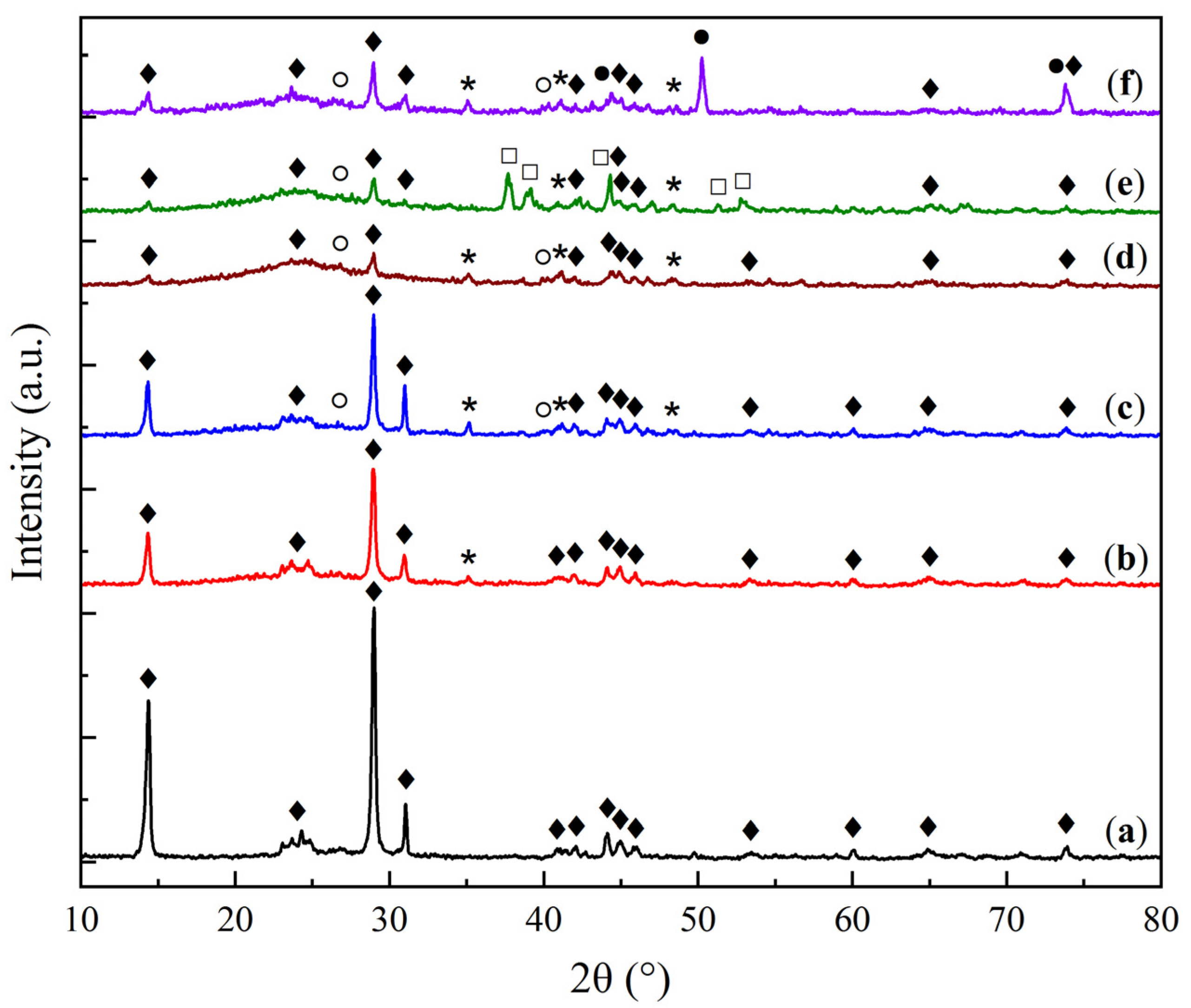
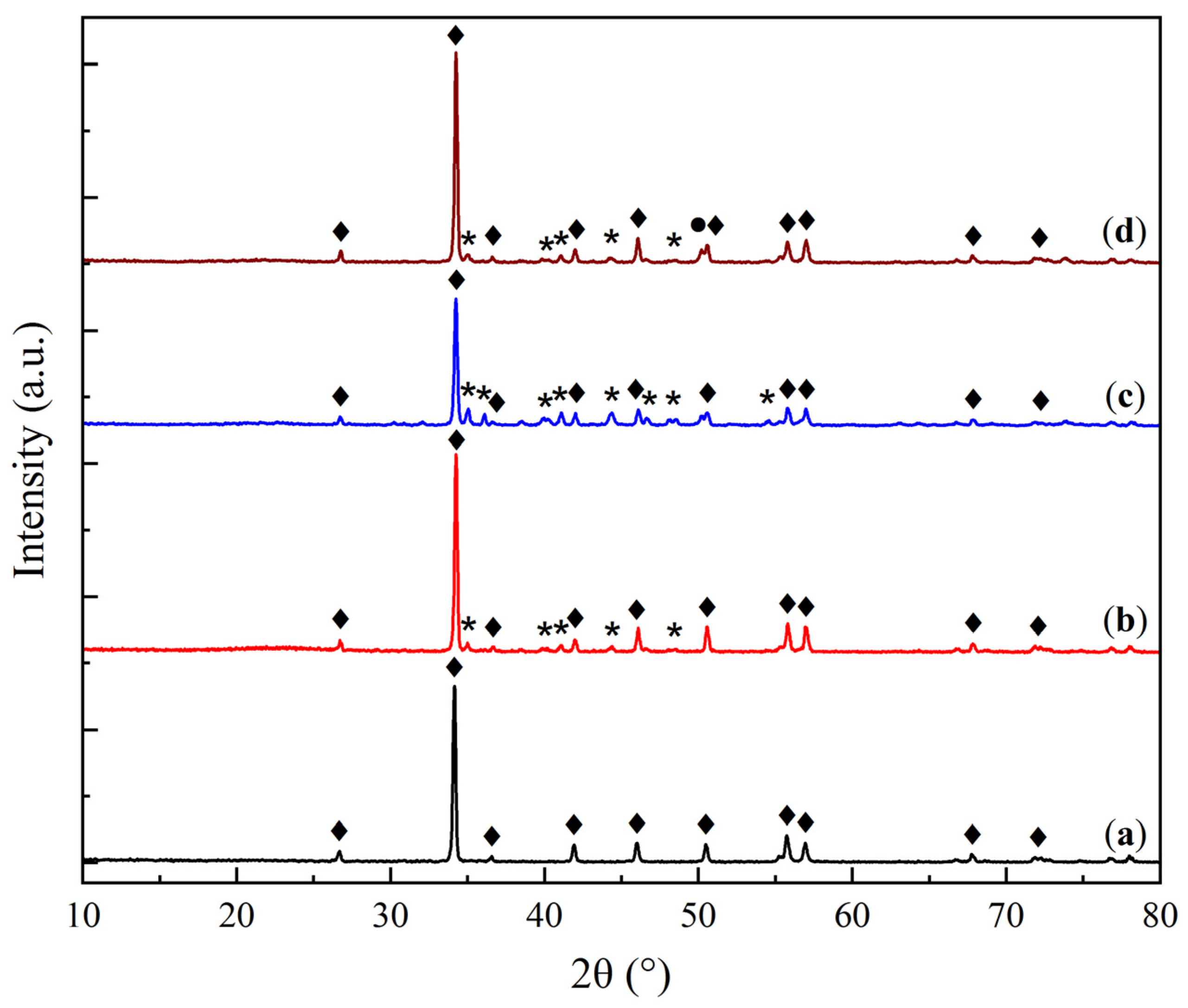
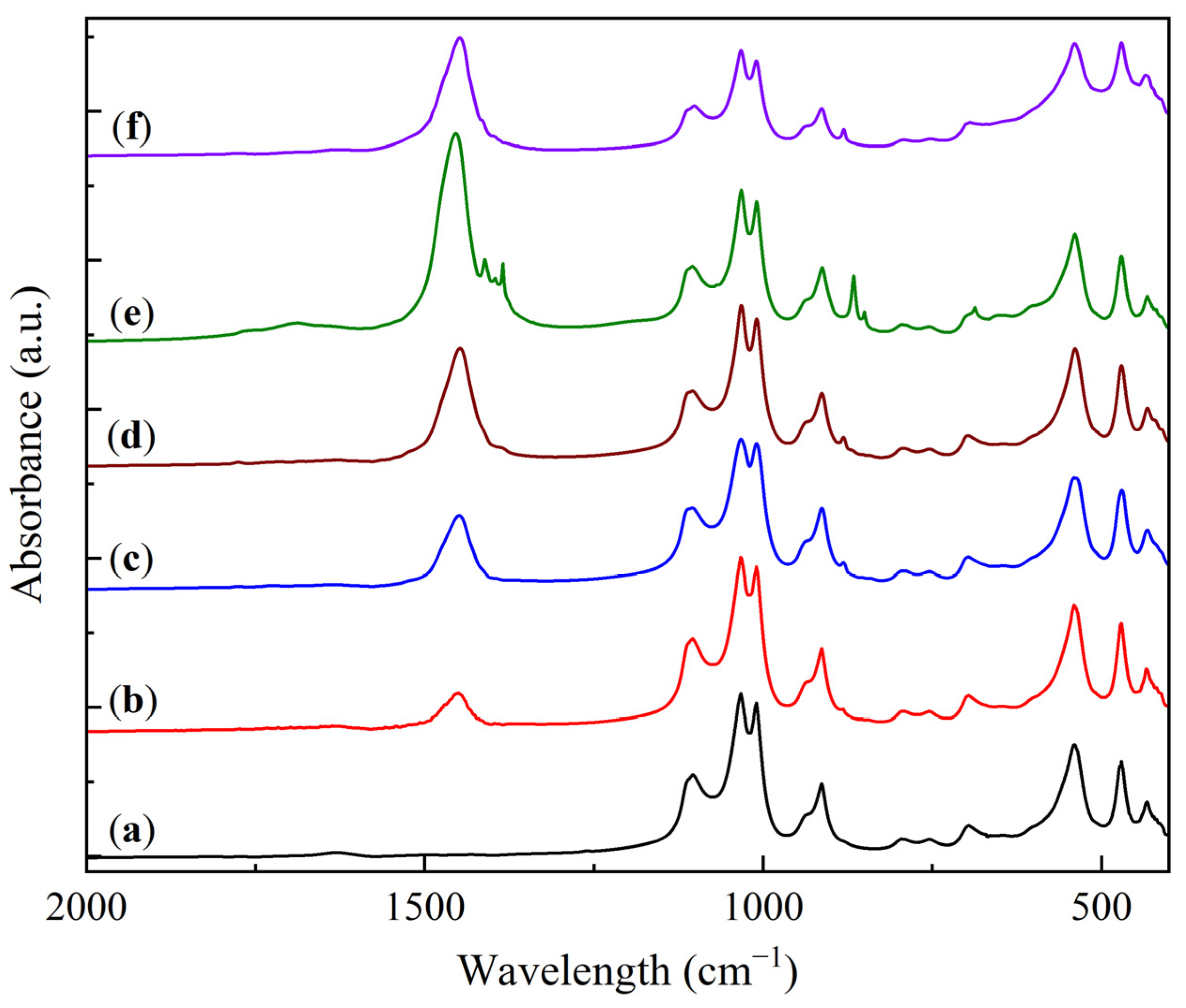
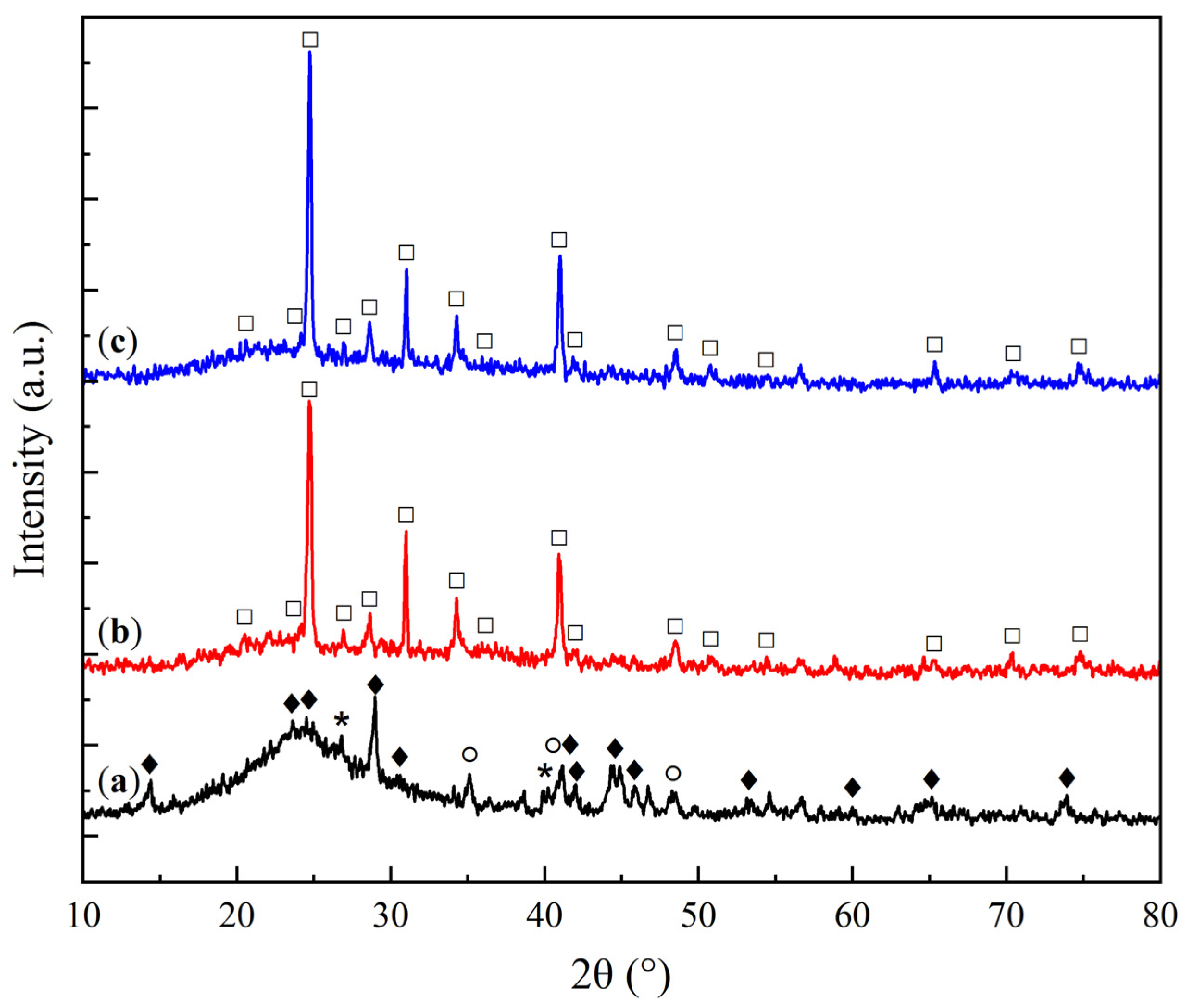
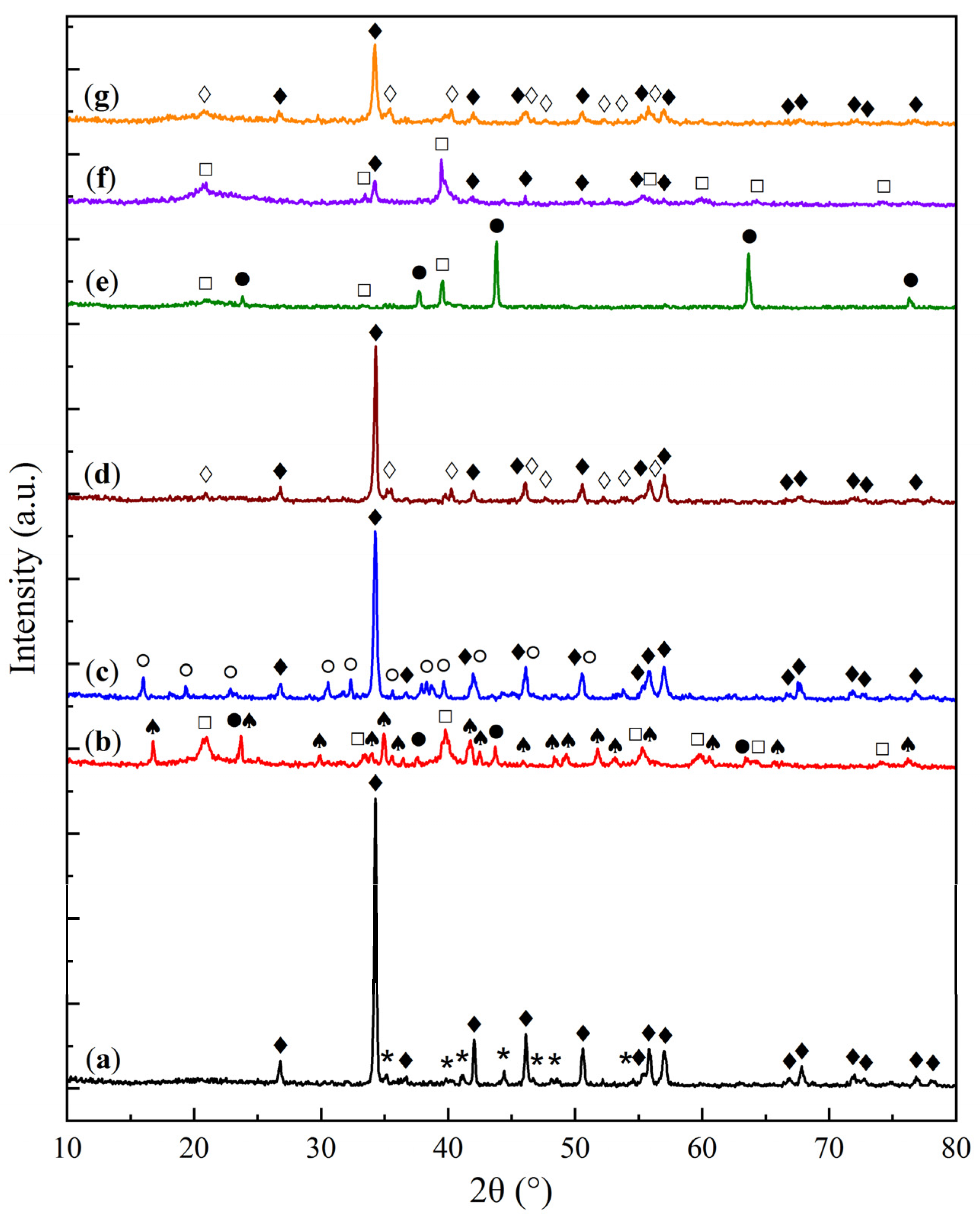
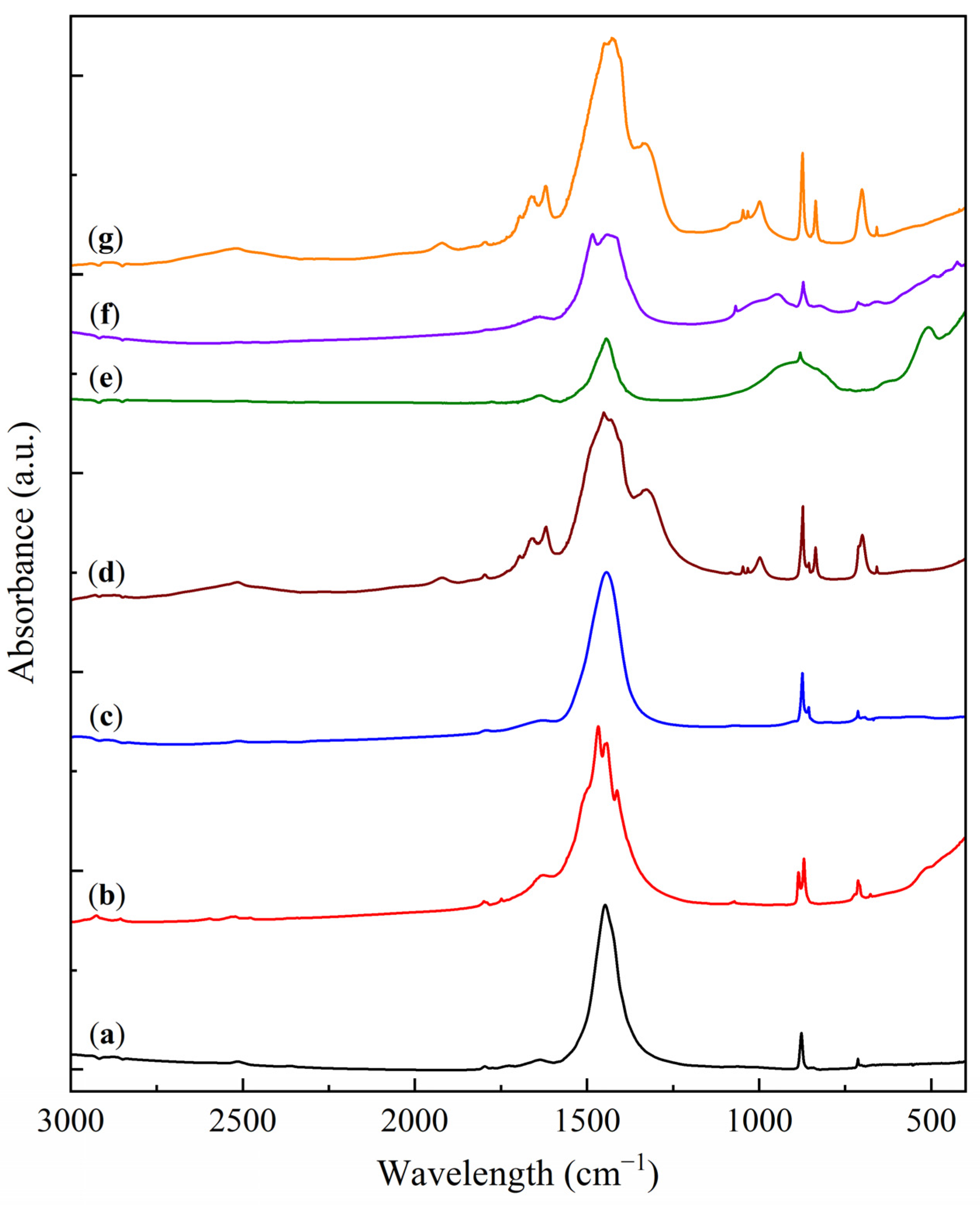
2.1. Physicochemical Characterization of Sorbent Samples

The synthesized sorbent samples, based on natural aluminosilicate (kaolin, Al2Si2O5(OH)4) and calcium carbonate (CaCO3), corresponding to the KS and LS series, respectively, were comprehensively characterized using a range of physicochemical techniques. The primary focus was on determining the phase and elemental composition of the samples and investigating their changes as a function of the active component loading (Na2CO3) and thermal treatment at elevated temperatures.
The X-ray diffraction (XRD) patterns of the KS and LS series samples are presented in Figure 1 and Figure 2, respectively, providing insights into the crystalline phases present in the sorbents and their transformation under varying conditions of Na2CO3 loading and thermal exposure.
The X-ray diffraction (XRD) analysis of the KS series samples (Figure 1) revealed the presence of a hydrated aluminosilicate phase corresponding to kaolinite (Al2Si2O5(OH)4, JCPDS 29-1488 [21]). In all Na2CO3-containing samples, regardless of the active component loading, a dispersed phase of sodium bicarbonate (NaHCO3) was detected (JCPDS 15-700 [22]). As the Na2CO3 loading increased, weak reflections corresponding to sodium carbonate (JCPDS 19-1130 [22]) were observed, and in the KS50 sample, additional peaks of thermonatrite (Na2CO3·H2O, JCPDS 8-448 [23]) were detected. The presence of this phase is likely due to local supersaturation of carbonate species during molding and drying, resulting from an excess of the active component. The introduction of magnesia (MgO) led to the appearance of strong reflections of the periclase phase (MgO, JCPDS 45–946 [24]).
With an increasing Na2CO3 loading in the KS series, a gradual decrease in the intensity of kaolinite reflections was observed, accompanied by an increase in the intensity of NaHCO3 peaks. This effect is attributed to the reduced fraction of the support, as well as the surface coverage of the support by a growing carbonate layer, as confirmed by SEM data.
In the LS series (Figure 2), the initial support is represented by calcite (CaCO3, JCPDS 37-1497 [25]). The XRD patterns of the LS sorbents show reflections of both calcite and natrite (Na2CO3). The LS25M sample demonstrated a weak reflection of the MgO phase, indicating its higher dispersion compared to KS25M.
As the active component loading increases in the LS series, the intensity of the calcite reflections decreases, while the intensity of the Na2CO3 peaks shows a slight increase. The relatively low intensity of carbonate phase peaks in both series is attributed to the high dispersion and amorphization of the active component on the support surface, as supported by the SEM data.
Crystallite size calculations using the Scherrer equation indicated that for the KS series, the kaolinite phase exhibits a crystallite size of 30–40 nm, while NaHCO3 shows a size range of 40–60 nm. As the Na2CO3 loading grows, the crystallite size of the support decreases, whereas the active component size increases (up to 30 and 60 nm for these two phases of the KS50 sample, respectively). A similar but less pronounced trend is observed for the LS series, where the calcite crystallite size is 55–60 nm, reaching a minimum of 55 nm for LS50, while the size of the active component ranges from 35 to 45 nm, increasing to 44 nm at the highest Na2CO3 loading. These results suggest that the crystallite sizes of both the support and the active phase remain relatively stable, with the active phase tending to form a fine, highly dispersed layer on the support surface.
The FTIR analysis results of the KS and LS series samples are presented in Figure 3 and Figure 4.
The FTIR spectra of the kaolin and the KS series samples (Figure 3) exhibit characteristic absorption bands in the range of 1100–400 cm−1 (1105, 1032, 1009, 913, 795, 753, 696, 540, 470, and 433 cm−1), which are typical of kaolinite [26,27]. The shape and position of the bands remain unchanged with increasing Na2CO3 loading, indicating the absence of significant interaction between the active component and the support.
In addition to the kaolinite bands, the FTIR spectra of the KS samples show absorption bands corresponding to carbonate and bicarbonate groups (1630, 1445, 1390, and 881 cm−1) [28,29]. The intensity of the broad band at 1445 cm−1 increases with the active component loading, reflecting the growing carbonate phase. In the KS50 sample, additional bands are observed at 1411, 1384, 866, 850, and 687 cm−1, also corresponding to carbonate (CO32−) vibrations. These bands are attributed to the high concentration of carbonate-containing phases in this sample. The introduction of magnesia (MgO) results in the appearance of a characteristic broad absorption band in the region of 500–400 cm−1 [30]. This observation confirms the presence of a finely dispersed MgO phase in the modified samples.
The FTIR spectra of the initial CaCO3 and the LS series samples display characteristic carbonate absorption bands at 1799, 1627, 1427, 876, and 713 cm−1. Upon the addition of Na2CO3, the primary carbonate band (1425–1450 cm−1) is split into two components corresponding to CaCO3 and Na2CO3 [28,29,31]. This effect is manifested as a gradual shift of the main band from 1427 cm−1 for pure CaCO3 to 1449 cm−1 in LS50, accompanied by the formation of a shoulder in the 1420–1430 cm−1 region. The introduction of MgO into the LS series produces a similar broad band in the 500–400 cm−1 region.
The SEM micrographs of the KS25 and LS25 samples are shown in Figure 5.
The SEM analysis provided insights into the influence of support type on the morphology of the sorbents. In the case of the Na2CO3/kaolin sorbents (Figure 5a,b), a characteristic plate-like structure of kaolin is observed [32], consisting of loosely packed aggregates of ordered lamellae. At higher magnification (Figure 5b), finely dispersed inclusions are detected on the surface of the support, evenly distributed and likely corresponding to carbonate-containing phases.
In the case of CaCO3-based sorbents (Figure 5c,d), the surface structure appears more amorphous, which is typical of natural limestone morphology. At a magnification of 3000× (Figure 5d), isometric crystallites of the active phase are visible, localized against the background of the amorphous support.
The results of the elemental composition analysis of the samples, obtained using energy-dispersive X-ray spectroscopy (EDS), are summarized in Table 1.
The elemental analysis data (Table 1) reveal distinct differences in the distribution of the active component (Na) between the KS and LS series. For the KS series, the Na concentration remains approximately constant as the Na2CO3 loading increases, but it is consistently higher than the nominal loading value. In contrast, the LS series exhibits a proportional increase in Na content with the increase in Na2CO3 loading in the sorbents.
This discrepancy is likely due to differences in the distribution mechanisms of the active phase. In the Na2CO3/kaolin sorbents, Na is uniformly distributed on the surface of the support, forming a thin yet continuous surface phase, which is readily detectable by SEM (analysis depth of 1–2 μm). Conversely, in the Na2CO3/CaCO3 sorbents, the active phase crystallizes within the bulk of the support, forming discrete crystallites. As a result, the Na content determined by SEM in the LS series closely correlates with the actual Na2CO3 loading in the sample.
The pore structure of the sorbents was characterized using the BET method. The results of texture and adsorption characteristics measurements are summarized in Table 2. Nitrogen adsorption–desorption isotherms for the KS25 and LS25 samples are shown in Figure 6a. Based on these data, the pore size distributions were calculated and plotted as d(log V)/dr vs. log r (Figure 6b), providing insights into the pore structure characteristics and dominant pore sizes in the sorbents.
The obtained data indicate that an increase in Na2CO3 in the sorbents, both for kaolin-based and CaCO3-based samples, leads to a noticeable increase in porosity. This observation suggests that Na2CO3 partially forms its own pore structure during recrystallization in the course of synthesis. Furthermore, considering the XRD results, it can be inferred that the wet mixing and extrusion process contributes to the partial disaggregation of support particles, further enhancing the pore volume and specific surface area.
According to the BET adsorption–desorption isotherms and pore size distributions (Figure 6), the KS25 sorbent is characterized by a predominantly slit-shaped pore structure. This morphology is likely associated with the intrinsic plate-like structure of kaolin aggregates, with the active phase forming a surface film. The pore size distribution curve for the KS25 sample reveals a structure dominated by large micropores and mesopores, with two maxima at ~10 and 25 nm.
In contrast, the pore structure of the LS25 sample is defined by bottle-shaped pores with a less ordered geometry, formed between the particles of the support and the active phase, with a similar pore size distribution. The pore volume and specific surface area of LS25 are somewhat lower than those of KS25, which can be attributed to both the different mechanisms of active phase formation and the lower porosity of the initial CaCO3 compared to kaolin (specific surface area of 3.5 m2/g for CaCO3 vs. 12.6 m2/g for kaolin).
The activity of the sorbents was determined by CO2 temperature-programmed desorption (TPD) using pre-saturated samples. The influence of the support on the behavior of the active phase during thermal desorption was studied. Sodium bicarbonate (NaHCO3, 99.9%) was used as a standard. The results of the study in the temperature range of 20–900 °C are presented in Figure 7.
The TPD profiles of the KS25 and LS25 samples exhibit low-temperature desorption peaks, which are analogous to the desorption peak of sodium bicarbonate (NaHCO3), corresponding to its decomposition into sodium carbonate (Na2CO3).
2NaHCO3 → Na2CO3 + H2O + CO2.
The desorption maxima for the samples with the active component are shifted to lower temperatures compared to pure NaHCO3. This shift can be attributed to the fine dispersion of the active phase over the support surface.
In addition to the low-temperature peaks, the KS25 sample shows a high-temperature peak at 283 °C, while the LS25 sample exhibits high-temperature peaks at 696 °C and 811 °C. These high-temperature peaks are likely associated with the decomposition of stable carbonate structures formed due to the interaction of the active phase with the functional groups of the support surface. For the KS25 sample, this may involve the formation of bridging bonds (Si–O–Na and Al–O–Na) resulting from the interaction of Na+ with hydroxyl groups of the kaolinite phase. In the case of LS25, the high-temperature peaks are attributed to the decomposition of the support phase with CaO formation.
The kinetic analysis of the CO2 desorption stages revealed that the activation energies for the low-temperature peaks, corresponding to NaHCO3 decomposition, are in the range of 65–70 kJ/mol, which is consistent with the literature data [33]. In contrast, the activation energies for the high-temperature peaks are significantly higher: 75 kJ/mol for KS25 and 116 kJ/mol for LS25. These higher values indicate the enhanced thermal stability of the respective phases.
The CO2 sorption capacities of the KS25 and LS25 series samples with varying active component loading are presented in Table 2 and Figure 8.
The sorption capacity values of the KS25 and LS25 series samples (Table 2, Figure 8) are consistent with the literature data for carbonate-based sorbents (1.8 mmol/g for 36.8% K2CO3/Al2O3 [16], 1.4 mmol/g for 30% Na2CO3/Al2O3) [20]. The results demonstrate a monotonic increase in sorption capacity with an increase in active phase loading in both series of sorbents. This trend indicates that CO2 has uninhibited access to the Na2CO3 surface, as well as the lack of strong interaction between the active phase and the support within the studied loading range.
However, for the samples with the highest Na2CO3 loading (KS50 and LS50), a deviation from the linear correlation of sorption capacity with Na2CO3 loading is observed. This deviation can be attributed to two main factors: the formation of new phases, such as thermonatrite (Na2CO3·H2O) in KS50, which may alter the adsorption behavior, as well as partial pore blockage due to the active component excess, reducing the accessible surface area for CO2 chemisorption. The observed decrease in specific activity, along with a sharp decline in formability, characterized by the number of fragmented granules during forming and drying, suggests that an optimal Na2CO3 loading of 25 wt.% is most suitable for both types of sorbents, providing a balance between efficiency and material cost.

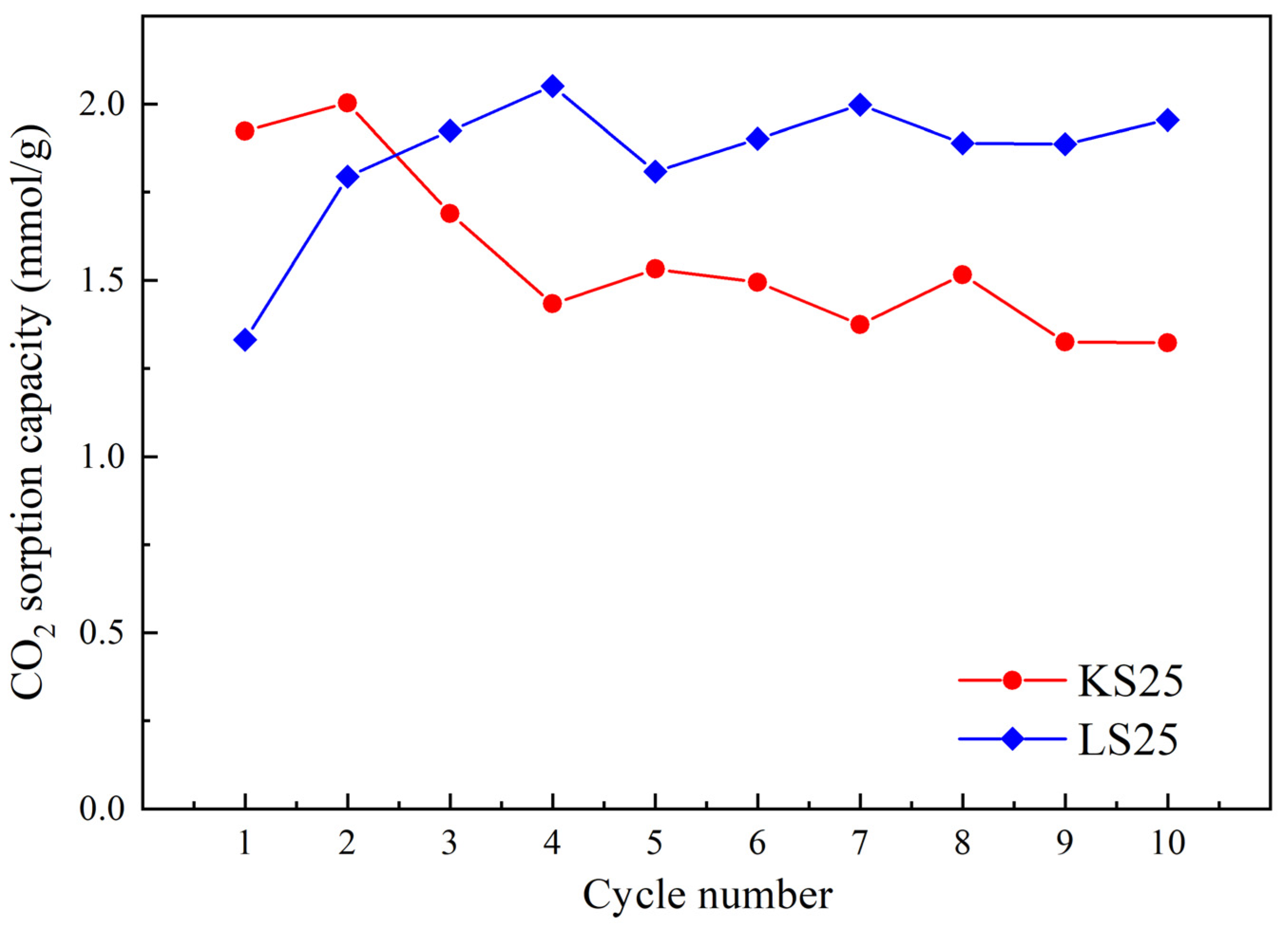
2.2. Thermal Stability and Cyclic Durability of the Supported Sorbents

In the development of carbonate-based sorbents for CO2 capture, particularly within the context of Ca-loops and the dry carbonate process, special attention is given to their stability under high-temperature conditions [10,11,12]. Thermal stability, determined as the material’s ability to maintain its structure and activity under both thermal shocks and cyclic heating conditions, is a critical parameter for CaO-based systems, which typically operate at temperatures of 800–950 °C [10,34,35]. However, it is also crucial for sorbents used in the DCP: it is known that the CO2 adsorption rate increases with the desorption temperature up to 300 °C [16]. This necessitates the use of materials that are either inherently thermally stable or capable of regeneration during practical operation. Despite the importance of this property, systematic studies on the thermal stability of such adsorbents remain limited, primarily focusing on alumina, activated carbon, and certain metal oxides [17,18].
To evaluate the thermal stability and regeneration capacity of the optimal sorbent samples (KS25 and LS25), the materials were subjected to high-temperature thermal treatment followed by regeneration in a humid environment and subsequent re-saturation in a humid CO2 flow. The impact of each stage was assessed using XRD and FTIR methods. The XRD results for the KS25 and LS25 sorbents after each treatment stage are presented in Figure 9 and Figure 10, respectively.
According to the XRD data (Figure 9 and Figure 10), when subjected to thermal treatment at 750 °C, the KS25 and LS25 sorbents undergo fundamentally different phase transformations. For the KS25 sample (Figure 9b), the calcination process leads to the disappearance of the characteristic reflections of kaolinite, NaHCO3, and Na2CO3 phases, accompanied by the formation of carnegieite (NaAlSiO3, JCPDS 11-220 [36]). This phase presumably forms as a result of the high-temperature interaction between kaolinite and Na2CO3, according to the following reaction:
Na2CO3 + Al2Si2O5(OH)4 → 2NaAlSiO4 + CO2 + 2H2O.
The calculated elemental ratio of Na:Al:Si in the calcined sample is approximately 1:1:1, which is consistent with the formation of NaAlSiO4 according to this reaction. Subsequent regeneration of the calcined KS25 sorbent (Figure 9c) did not cause the restoration of the initial phases, indicating that the phase transition is irreversible under the given thermal conditions.
In the case of the LS25 sorbent (Figure 10b), calcination at 750 °C leads to the disappearance of CaCO3 and Na2CO3 diffraction maxima and the appearance of peaks corresponding to CaO (JCPDS 37-1497 [25]), Ca(OH)2 (JCPDS 44-1481 [25]), and a mixed carbonate phase—nyerereite (Na2Ca(CO3)2, JCPDS 33-1221 [37]). The formation of nyerereite is likely the result of a reaction between the support and the active component:
Na2CO3 + CaCO3 → Na2Ca(CO3)2.
The presence of an excess of CaCO3 in the initial sorbent explains the simultaneous formation of the mixed salt and the CaO and Ca(OH)2 phases. The latter phase likely forms due to the interaction of CaO with atmospheric moisture.
Regeneration of the LS25(750) sample in a humid environment (Figure 10c) resulted in the formation of CaCO3 and the hydrated double salt—gaylussite (Na2Ca(CO3)2·5H2O, JCPDS 21-343 [38]). The formation of CaCO3 is attributed to the reaction of CaO and Ca(OH)2 with the CO2 present in the atmosphere [25], while gaylussite is formed through the hydration of nyerereite [37,38].
Re-saturation of the regenerated sample (Figure 10d) led to the decomposition of the double salt with the formation of CaCO3 and NaHCO3, likely according to the following reaction:
Na2Ca(CO3)2·5H2O + CO2 → 2NaHCO3 + CaCO3 + 4H2O.
To further assess the thermal stability and regeneration capacity of the Na2CO3/CaCO3 system under severe conditions, the LS25 sample was subjected to thermal treatment at 1000 °C—a temperature exceeding both the melting point of Na2CO3 and the decomposition temperature of CaCO3 [39]. The XRD pattern of the LS25(1000) sample (Figure 10e) shows the presence of CaO and Ca(OH)2 phases, while no reflections corresponding to nyerereite are observed. This result is consistent with the literature data indicating the instability of this double salt under such conditions [39]. The absence of diffraction maxima of sodium carbonates is likely due to the amorphization of Na2CO3 upon melting. Despite their complete amorphization at 1000 °C, Na-containing phases are capable of partial regeneration, presumably due to the recrystallization of the support phase in these conditions.
Following regeneration of this sample in a humid environment (Figure 10f), Ca(OH)2 and CaCO3 phases are detected, but still no Na-containing phases are present. This observation suggests that the active phase remains in an amorphous state. Subsequent carbonation (Figure 10g) leads to the formation of NaHCO3 and CaCO3 phases, similar to the behavior observed for LS25(750+H2O+CO2). These results confirm the ability of the Na2CO3/CaCO3 system to restore its sorption capacity even after thermal treatment at 1000 °C.
The results of the FTIR study of the heat treatment of the KS25 and LS25 samples are presented in Figure 11 and Figure 12.
According to the FTIR data, thermal treatment of the KS25 sorbent at 750 °C (Figure 11b) leads to the disappearance of the characteristic absorption bands of kaolinite in the region of 1100–400 cm−1. Instead, three broad bands appear at 982, 694, and 465 cm−1, corresponding to the spectra of framework aluminosilicates such as nepheline or carnegieite [40], in agreement with the XRD data. Upon regeneration of the sample (Figure 11c), the FTIR spectrum remains unchanged, confirming the irreversible phase transition of kaolinite under thermal treatment at 750 °C.
In the case of LS25, thermal treatment at 750 °C (Figure 12b) results in the splitting of the broad band at 1400–1500 cm−1 into four distinct peaks (1507, 1467, 1443, and 1413 cm−1), along with the appearance of new bands at 886, 870, and 712 cm−1. These absorption bands are characteristic of nyerereite [41], while a broad halo at 400–550 cm−1 indicates the presence of CaO [30].
After regeneration of the LS25 sample (Figure 12c), the splitting effect in the 1400–1500 cm−1 region disappears, and the spectrum is dominated by absorption bands at 1447, 874, 856, and 713 cm−1, characteristic of carbonate groups in gaylussite [42]. Subsequent carbonation (Figure 12d) results in the appearance of bands corresponding to both CaCO3 (713, 875, 1428 cm−1) and NaHCO3 (700, 835, 995, 1032, 1047, 1328, 1607, 1661, 1923 cm−1) [28,29]. The resulting spectrum is a superposition of the characteristic bands of CO32− and HCO3 groups, corresponding to CaCO3 and NaHCO3 phases, respectively.
Thermal treatment of LS25 at 1000 °C (Figure 12e) leads to the retention of weak carbonate bands (1444 and 880 cm−1), along with the appearance of broad absorption regions (400–500 cm−1) characteristic of CaO [30]. This indicates the decomposition of CaCO3 to CaO, while Na2CO3 melts and transitions to an amorphous state without decomposition. After regeneration in a humid medium (Figure 12f), the CaO halo at 400–500 cm−1 disappears, while the intensity of the carbonate bands increases, indicating the hydration of CaO to Ca(OH)2, followed by partial carbonation in air. The spectrum of the LS25(1000+H2O+CO2) sample (Figure 12g) is similar to that of LS25(750+H2O+CO2), confirming the regeneration capability of the system after high-temperature treatment.
The sorption capacity values of the LS25 samples at different stages of thermal treatment and regeneration are summarized in Table 3.
Thermal treatment of the KS25 sample at 750 °C resulted in a 93.8% reduction in CO2 sorption capacity compared to the initial value. Regeneration failed to restore the capacity value, indicating irreversible deactivation of the sorbent. This deactivation is likely due to the formation of an inactive carnegieite phase and sintering of the pore structure.
In contrast, the LS25 sorbent demonstrated significantly better thermal stability. After thermal treatment at 750 °C followed by regeneration, the sorption capacity decreased by 6.6%. This capacity retention can be attributed to the recovery of carbonate phases and the formation of gaylussite, which exhibits adsorption activity, unlike the inactive nyerereite phase. After subjecting the LS25 sample to thermal treatment at 1000 °C followed by regeneration, the sorption capacity decreased by 31.2%, indicating a decline in regeneration efficiency at temperatures above the melting point of Na2CO3 and the decomposition temperature of the support.
To further assess the thermal stability of the sorbents, cyclic adsorption–desorption tests were performed on the KS25 and LS25 samples. The results are presented in Figure 13.
As shown in Figure 13, the KS25 sample exhibits a decrease in CO2 sorption capacity during the first four adsorption–desorption cycles, after which the capacity stabilizes at a constant level. In contrast, the LS25 sorbent shows an initial increase in sorption capacity during the first few cycles, followed by stabilization at a level higher than the initial value. This increase can be explained by several possible mechanisms, including partial removal of residual water and recrystallization of the amorphous Na2CO3 phase during the first cycles, contributing to an increase in the available surface; the formation of nyerereite and then gaylussite through the interaction between the components during the thermal cycles; and partial destruction of agglomerates of the active phase, improving wettability and the contact surface between CO2, H2O and Na2CO3. These results confirm the superior durability of the CaCO3-based sorbent under repeated adsorption–desorption cycles. This quality, combined with high thermal stability and regeneration capability, makes LS25 a promising candidate for practical applications in CO2 capture technologies.

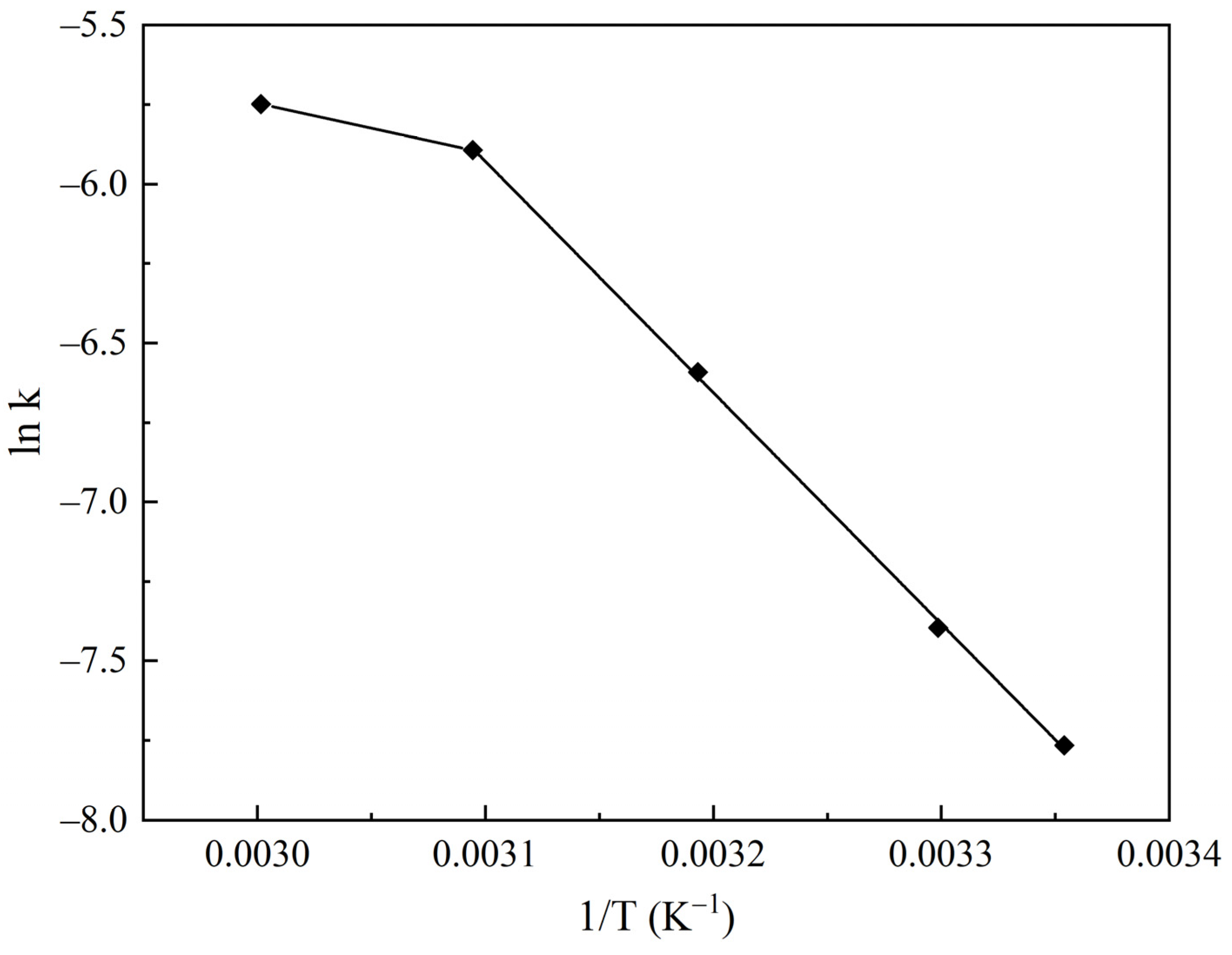
2.3. Kinetic Study of CO2 Adsorption on the Na2CO3/CaCO3 Sorbent

Based on the results of the studies, the LS25 sorbent was selected for the investigation of CO2 chemisorption kinetics due to its superior stability.
Various models have been proposed to describe the kinetics of CO2 uptake by solid sorbents based on alkali metal carbonates, including first-order and second-order reaction equations with respect to CO2, as well as the Avrami–Erofeev equation [11,43,44,45]. Guo et al. [44] showed the applicability of a model that accounts for diffusion processes at the interface between the bicarbonate and carbonate phases—the reaction product and the initial active component—for the K2CO3/AC system. Quantum chemical calculations (DFT) of the Na2CO3 carbonation reaction [46,47] further confirmed this mechanism, which is based on the diffusion of CO2 and H2O (or H+ and HCO3 ions) to the phase boundary between NaHCO3 and Na2CO3.
Taking this into account, the present study employed the approach proposed in [44] to analyze the carbonation kinetics of the LS25 sorbent, using the shrinking core model, which allows for the derivation of the following equation:
t = R k p C O 2 0 p H 2 O 0 1 1 f t 1 3   ,
where t is the current time of the carbonation reaction (min), R is the average radius of the sorbent particles (mm), k is the carbonation rate constant (cm/min), p C O 2 0 , p H 2 O 0 are the partial pressures of the initial components (CO2 and H2O), atm, and f(t) = Q C O 2 / n C O 2 is the carbonation degree, defined as the ratio of the amount of CO2 adsorbed to the theoretical amount of CO2 that can be adsorbed by the sorbent sample with the given Na2CO3 concentration.
The kinetic study involved measuring the amount of CO2 captured by the sorbent over time under fixed conditions (temperature and gas composition). The resulting kinetic curves, representing the change in the carbonation degree as a function of time at various sorption temperatures, are shown in Figure 14.
Contrary to the results reported for the K2CO3/AC system [44], where an increase in adsorption temperature led to a decrease in sorption efficiency, the LS25 sorbent demonstrated a different behavior, with an increase in adsorption temperature resulting in higher final carbonation degrees and prolonged effective sorbent operation time. This discrepancy is likely due to the difference in the nature of the support: in carbon-based sorbents (K2CO3/AC), increasing the temperature reduces sorption efficiency due to the weakening of physical adsorption. In the Na2CO3/CaCO3 system, sorption is likely of a mostly chemical nature, as suggested by the low values of specific surface area and pore volume of the sorbent.
The carbonation curves (Figure 14) were processed using the shrinking core model. The calculated values of the adsorption rate constants are presented in Table 4, and their temperature dependence is illustrated in the Arrhenius plot (Figure 15).
In the temperature range of 25–50 °C, the carbonation kinetics are well described by the shrinking core model, with an activation energy of 60 kJ/mol. This value indicates that the process is not limited by diffusion constraints but rather by a chemical reaction at the phase boundary between NaHCO3 and Na2CO3. At higher temperatures, the rate increase slows down, which can be attributed to diffusion limitations: as the adsorption temperature is raised, the rate-determining step shifts from chemical reaction (chemisorption) to mass transfer in the pore structure of the sorbent, presumably defined by Knudsen diffusion [48,49]. These findings confirm the high efficiency of the LS25 sorbent for low-temperature CO2 capture.

3. Materials and Methods

3.1. Synthesis of Sorbent Samples

The sorbent samples were synthesized by mixing dry powders of the support material (kaolin or calcium carbonate) and the active component (Na2CO3). The resulting dry mixture was moistened with water until a mass suitable for molding was obtained (moisture content 20%). The sorbents were granulated using an extrusion method with a screw extruder equipped with 3 mm diameter dies. The resulting extrudates were cured overnight and then dried at 120 °C for 4 h.
The sorbents were prepared with active component loadings up to 50 wt.% Na2CO3. Kaolin-based samples were designated as KS, while those based on CaCO3 were labeled as LS, with the percentage of Na2CO3 specified in the sample code (e.g., KS25 for 25 wt.% Na2CO3). In addition, to enhance mechanical stability and overall performance, some samples were modified with magnesia (MgO) at 10 wt.% of the support mass, which is reported to improve the durability of carbonate-containing materials [50,51]. These modified samples were labeled KS25M and LS25M, respectively.
For sorption capacity determination, the sorbent samples were pre-saturated with CO2. Saturation was carried out in a flow quartz reactor with a humid gas mixture (2% CO2, 5% H2O, balance He) for 8 h at room temperature.
To assess thermal stability, the KS25 and LS25 samples were subjected to high-temperature treatment, followed by regeneration and re-saturation with CO2. Samples calcined at a specific temperature (T, °C) were labeled as KS25(T) and LS25(T). Samples calcined and regenerated in a humid environment (5% H2O, balance He) were labeled as KS25(T+H2O) and LS25(T+H2O). Samples that underwent further re-saturation in a wet CO2 stream (2% CO2, 5% H2O, balance He) were labeled as KS25(T+H2O+CO2) and LS25(T+H2O+CO2), respectively.

3.2. Characterization of Sorbent Samples

The physicochemical characteristics of the sorbent samples were investigated using a range of analytical techniques. X-ray diffraction (XRD) patterns were obtained using a DRON-4-07 powder diffractometer (Burevestnik, Saint-Petersburg, Russia) with Co Kα radiation and a Ni filter, operating at the parameters of 30 kV and 20 mA. The scanning range was 10–80°, with a 0.02° step size and a 2°/min scanning speed. The average crystallite size was calculated as follows using the Scherrer equation [19]:
d = 0.9 λ B cos θ   ,
where d is the crystallite mean size (nm), λ = 0.1789 is the wavelength (nm), B is the full peak width at half maximum (rad), and θ is the diffraction angle (°).
The structure of the samples was studied using the SEM method with a low-vacuum scanning electron microscope JSM-6610LV (JEOL, Tokyo, Japan) equipped with an energy-dispersive X-ray spectroscopy (EDS) module for surface elemental analysis.
The FTIR study was conducted on a Nicolet iS5 FTIR spectrometer (Thermo Fisher Scientific, Milan, Italy) at room temperature in the range of 4000–400 cm−1. The samples were pressed into KBr pellets.
The specific surface area and pore characteristics of the samples were measured using a Thermo Scientific Surfer gas adsorption analyzer (Thermo Fisher Scientific, Italy) at 77 K with nitrogen (N2) used as the adsorbate, and the specific surface area was calculated by the Brunauer–Emmett–Teller (BET) method.
The CO2 sorption capacity of pre-saturated, crushed sorbent samples (0.5 g) was determined by TPD using a flow quartz reactor equipped with a Chromatek-Crystal 5000 gas chromatograph (Chromatek, Yoshkar-Ola, Russia). The desorption was performed in a He flow (30 cm3/min) at a linear heating rate of 10 °C/min up to 900 °C (up to 150 °C in the case of adsorption–desorption cycles). The desorbed CO2 was detected using a thermal conductivity detector (TCD). For the kinetic analysis of TPD data, the curves were integrated and then processed in accordance with the 1st order equation, considering a constant rate of temperature increase [52].
The kinetics of CO2 adsorption were studied using pre-saturated, crushed sorbent samples: after TPD up to 150 °C, the samples were rapidly cooled to the target temperature and maintained in a liquid-thermostatted reactor under a humid CO2 flow (2% CO2, 5% H2O, balance He) at a flow rate of 30 cm3/min.

4. Conclusions

The study investigated molded Na2CO3/support sorbents with kaolin and CaCO3 as supports (series KS and LS, respectively) with varying active component loadings, confirming their effectiveness as CO2 sorbents under the dry carbonate process conditions (adsorption at 50–80 °C, desorption at 100–150 °C). Physicochemical analysis of the sorbent samples (XRD, FTIR, SEM) revealed the presence of the phases of the support (kaolinite or calcite) and the carbonate and bicarbonate phases, whose intensity increased with the rising Na2CO3 loading. It was established that the morphology of the support significantly affects the distribution of the active phase. In kaolin-based sorbents, Na2CO3 forms a surface film on the plate-like structure of the support. In CaCO3-based sorbents, the active component predominantly crystallizes within the bulk. This difference is also confirmed to be reflected in the pore structure formation. The optimal Na2CO3 content in both series was determined to be 25 wt.%, providing the best balance between sorption capacity and technological properties.
The thermal stability and cyclic performance of the sorbents with optimal Na2CO3 content (KS25 and LS25) were thoroughly studied. It was found that the thermal treatment of KS25 at 750 °C led to the formation of an inactive carnegieite phase and an irreversible loss of sorption capacity (93.8% reduction). In contrast, LS25 retained its regenerative capacity due to the formation of nyerereite (Na2Ca(CO3)2) upon thermal treatment and gaylussite (Na2Ca(CO3)2·5H2O) upon subsequent hydration. The gaylussite was further converted into NaHCO3 and CaCO3 upon re-saturation in CO2 flow, enabling nearly complete regeneration of the active phase. Thermal treatment of LS25 at 1000 °C resulted in a partial loss of activity (31.2% reduction), attributed to the amorphization of Na2CO3 upon melting. However, the sorbent retained its ability to regenerate, likely due to the recrystallization of NaHCO3 from the amorphous phase. The CaCO3 support underwent decomposition to CaO, which, after hydration and carbonation, returned to its original CaCO3 state.
Cyclic adsorption–desorption tests demonstrated that LS25 exhibited high stability over multiple cycles without degradation, unlike KS25, which showed a decrease in sorption capacity after the first four cycles. These findings highlight the superior thermal stability, regeneration capability, and operational durability of CaCO3-based sorbents.
The kinetics of CO2 chemisorption on the LS25 sorbent were investigated using the shrinking core model. It was determined that, in the temperature range of 25–50 °C, the process is governed by chemical reaction at the phase boundary between NaHCO3 and Na2CO3, with an activation energy of 60 kJ/mol. The observed increase in adsorption efficiency with temperature confirms the chemical nature of the sorption process. At higher temperatures (60 °C), a diffusion-limited regime is manifested.
In summary, the results of this study demonstrate that supported alkali metal carbonate sorbents are highly promising materials for low-temperature dry CO2 capture from flue gases. Moreover, they offer significant potential as the basis for sorbent–catalyst systems for the conversion of captured CO2 into valuable chemical products within an integrated reaction scheme.

Author Contributions

Conceptualization, A.S. (Alexandr Sass) and I.T.; methodology, A.B.; software, B.K.; validation, B.K. and A.S. (Alexandr Sass); formal analysis, K.R. and A.S. (Adel Sarsenova); investigation, D.Z. and Y.B.; data curation, A.K. and T.D.; writing—original draft preparation, A.S. (Alexandr Sass) and I.T.; writing—review and editing, A.B.; visualization, A.K.; supervision, M.Z.; project administration, A.K.; funding acquisition, A.K. and A.S. (Adel Sarsenova). All authors have read and agreed to the published version of the manuscript.

Funding

This research was funded by the Science Committee of the Ministry of Science and Higher Education of the Republic of Kazakhstan, grant number BR21882241.

Institutional Review Board Statement

Not applicable.

Informed Consent Statement

Not applicable.

Data Availability Statement

The data presented in this study are available upon request from the corresponding authors.

Acknowledgments

The authors are especially grateful to the staff of the Laboratory of Physical Research Methods.

Conflicts of Interest

The authors declare no conflicts of interest. The funders had no role in the design of the study; in the collection, analyses, or interpretation of data; in the writing of the manuscript; or in the decision to publish the results.

Abbreviations

The following abbreviations are used in this manuscript:
CCUSCarbon Capture, Utilization, and Storage
CCUCarbon Capture and Utilization
CCSCarbon Capture and Storage
DCPDry Carbonate Process
XRDX-ray Diffraction
JCPDSJoint Committee on Powder Diffraction Standards
SEMScanning Electron Microscopy
FTIRFourier-Transform Infrared Spectroscopy
EDSEnergy-Dispersive X-ray Spectroscopy
BETBrunauer–Emmett–Teller Method
TPDTemperature-Programmed Desorption
ACActive Carbon
DFTDensity Functional Theory
TCDThermal Conductivity Detector

References

  1. IEA. CO2 Emissions in 2023: Global Energy Review; International Energy Agency: Paris, France, 2024; Available online: https://www.iea.org/reports/co2-emissions-in-2023 (accessed on 13 May 2025).
  2. Hsiao, C.M. Economic growth, CO2 emissions quota and optimal allocation under uncertainty. Sustainability 2022, 14, 8706. [Google Scholar] [CrossRef]
  3. Li, Z.; Wang, B. A bibliometric analysis of carbon allowances in the carbon emissions trading market. Energies 2024, 18, 57. [Google Scholar] [CrossRef]
  4. Zhai, X.; Yang, X.; Vukovic, D.B.; Dinets, D.A.; Liu, Q. Carbon emissions trading policy and regional energy efficiency: A quasi-natural experiment from China. Energies 2025, 18, 1161. [Google Scholar] [CrossRef]
  5. Błażejowska, M.; Czarny, A.; Kowalska, I.; Michalczewski, A.; Stępień, P. The effectiveness of the EU ETS policy in changing the energy mix in selected European countries. Energies 2024, 17, 4243. [Google Scholar] [CrossRef]
  6. Nath, F.; Mahmood, M.N.; Yousuf, N. Recent advances in CCUS: A critical review on technologies, regulatory aspects and economics. Geoenergy Sci. Eng. 2024, 238, 212726. [Google Scholar] [CrossRef]
  7. Ampomah, W.; Morgan, A.; Koranteng, D.O.; Nyamekye, W.I. CCUS perspectives: Assessing historical contexts, current realities, and future prospects. Energies 2024, 17, 4248. [Google Scholar] [CrossRef]
  8. Saxena, A.; Gupta, J.P.; Tiwary, J.K.; Kumar, A.; Sharma, S.; Pandey, G.; Biswas, S.; Chaturvedi, K.R. Innovative pathways in carbon capture: Advancements and strategic approaches for effective carbon capture, utilization, and storage. Sustainability 2024, 16, 10132. [Google Scholar] [CrossRef]
  9. Raganati, F.; Ammendola, P. CO2 post-combustion capture: A critical review of current technologies and future directions. Energy Fuels 2024, 38, 13858–13905. [Google Scholar] [CrossRef]
  10. Chang, R.; Wu, X.; Cheung, O.; Liu, W. Synthetic solid oxide sorbents for CO2 capture: State-of-the art and future perspectives. J. Mater. Chem. A 2022, 10, 1682–1705. [Google Scholar] [CrossRef]
  11. Zentou, H.; Aliyu, M.; Abdalla, M.A.; Abdelaziz, O.Y.; Hoque, B.; Alloush, A.M.; Tayeb, I.M.; Patchigolla, K.; Abdelnaby, M.M. Advancements and challenges in adsorption-based carbon capture technology: From fundamentals to deployment. Chem. Rec. 2025, 25, e202400188. [Google Scholar] [CrossRef]
  12. Saenz Cavazos, P.A.; Hunter-Sellars, E.; Iacomi, P.; McIntyre, S.R.; Danaci, D.; Williams, D.R. Evaluating solid sorbents for CO2 capture: Linking material properties and process efficiency via adsorption performance. Front. Energy Res. 2023, 11, 1167043. [Google Scholar] [CrossRef]
  13. Nelson, T.O.; Coleman, L.J.; Green, D.A.; Gupta, R.P. The dry carbonate process: Carbon dioxide recovery from power plant flue gas. Energy Procedia 2009, 1, 1305–1311. [Google Scholar] [CrossRef]
  14. Zhao, C.; Chen, X.; Anthony, E.J.; Jiang, X.; Duan, L.; Wu, Y.; Dong, W.; Zhao, C. Capturing CO2 in flue gas from fossil fuel-fired power plants using dry regenerable alkali metal-based sorbent. Prog. Energy Combust. Sci. 2013, 39, 515–534. [Google Scholar] [CrossRef]
  15. Medina-Carrasco, S.; Valverde, J.M. Crystallographic and morphological transformation of natrite and nahcolite in the dry carbonate process for CO2 capture. Cryst. Growth Des. 2018, 18, 4578–4592. [Google Scholar] [CrossRef]
  16. Ma, J.; Zhong, J.; Bao, X.; Chen, X.; Wu, Y.; Cai, T.; Liu, D.; Liang, C. Continuous CO2 capture performance of K2CO3/Al2O3 sorbents in a novel two-stage integrated bubbling-transport fluidized reactor. Chem. Eng. J. 2021, 404, 126465. [Google Scholar] [CrossRef]
  17. Lee, S.C.; Choi, B.Y.; Lee, T.J.; Ryu, C.K.; Ahn, Y.S.; Kim, J.C. CO2 absorption and regeneration of alkali metal-based solid sorbents. Catal. Today 2006, 111, 385–390. [Google Scholar] [CrossRef]
  18. Qin, C.; Yin, J.; Ran, J.; Zhang, L.; Feng, B. Effect of support material on the performance of K2CO3-based pellets for cyclic CO2 capture. Appl. Energy 2014, 136, 280–288. [Google Scholar] [CrossRef]
  19. Masoud, N.; Bordanaba-Florit, G.; Van Haasterecht, T.; Bitter, J.H. Effect of support surface properties on CO2 capture from air by carbon-supported potassium carbonate. Ind. Eng. Chem. Res. 2021, 60, 13749–13755. [Google Scholar] [CrossRef]
  20. Xu, Z.; Ma, J.; Chen, X.; Wang, C.; Tao, Z.; Liu, D.; Liang, C. CO2 capture performance of Na2CO3/γ-Al2O3 sorbent modified with organic acid. Energy Fuels 2024, 38, 7148–7157. [Google Scholar] [CrossRef]
  21. Baizhumanova, T.; Tungatarova, S.; Kaumenova, G.; Zhumabek, M.; Kassymkan, K. Catalytic oxidation of C3–C4 mixture into industrial important chemical products. Orient. J. Chem. 2019, 35, 404–408. [Google Scholar] [CrossRef]
  22. Ling, C.; Wang, Z.; Gui, C.; Tang, Z. High temperature CO2 capture performance and kinetic analysis of Na4SiO4 ceramics. Ceram. Int. 2022, 48, 33048–33057. [Google Scholar] [CrossRef]
  23. Shang, H.; Ouyang, T.; Yang, F.; Kou, Y. A biomass-supported Na2CO3 sorbent for flue gas desulfurization. Environ. Sci. Technol. 2003, 37, 2596–2599. [Google Scholar] [CrossRef]
  24. Meshkani, F.; Rezaei, M. Facile synthesis of nanocrystalline magnesium oxide with high surface area. Powder Technol. 2009, 196, 85–88. [Google Scholar] [CrossRef]
  25. Lekatou, A.G.; Tsouli, S. Cyclic polarization of corrugated austenitic stainless steel rebars in acid rain: Effect of fly ash, pH and steel type. Corros. Mater. Degrad. 2022, 3, 75–100. [Google Scholar] [CrossRef]
  26. Kristóf, J.; Frost, R.L.; Felinger, A.; Mink, J. FTIR spectroscopic study of intercalated kaolinite. J. Mol. Struct. 1997, 410, 119–122. [Google Scholar] [CrossRef]
  27. Zich, D.; Zacher, T.; Darmo, J.; Szöcs, V.; Lorenc, D.; Janek, M. Far-infrared investigation of kaolinite and halloysite intercalates using terahertz time-domain spectroscopy. Vib. Spectrosc. 2013, 69, 1–7. [Google Scholar] [CrossRef]
  28. Joshi, S.; Kalyanasundaram, S.; Balasubramanian, V. Quantitative analysis of sodium carbonate and sodium bicarbonate in solid mixtures using Fourier transform infrared spectroscopy (FT–IR). Appl. Spectrosc. 2013, 67, 841–845. [Google Scholar] [CrossRef]
  29. Đorđević, N.; Vlahović, M.; Mihajlović, S.; Martinović, S.; Vušović, N.M.; Šajić, J.L. Fourier-transform infrared spectroscopy analysis of mechanochemical transformation kinetics of sodium carbonate to bicarbonate. Sci. Sinter. 2022, 54, 481–494. [Google Scholar] [CrossRef]
  30. Hofmeister, A.M.; Keppel, E.; Speck, A.K. Absorption and reflection infrared spectra of MgO and other diatomic compounds. Mon. Not. R. Astron. Soc. 2003, 345, 16–38. [Google Scholar] [CrossRef]
  31. Gupta, U.; Singh, V.K.; Kumar, V.; Khajuria, Y. Experimental and theoretical spectroscopic studies of calcium carbonate (CaCO3). Mater. Focus 2015, 4, 164–169. [Google Scholar] [CrossRef]
  32. Zbik, M.; Smart, R.S.C. Nanomorphology of kaolinites: Comparative SEM and AFM studies. Clays Clay Miner. 1998, 46, 153–160. [Google Scholar] [CrossRef]
  33. Dutcher, B.; Fan, M.; Leonard, B. Use of multifunctional nanoporous TiO(OH)2 for catalytic NaHCO3 decomposition-eventually for Na2CO3/NaHCO3 based CO2 separation technology. Sep. Purif. Technol. 2011, 80, 364–374. [Google Scholar] [CrossRef]
  34. Hashemi, S.M.; Mohamedali, M.; Sedghkerdar, M.H.; Mahinpey, N. Stability of CaO-based sorbents under realistic calcination conditions: Effect of metal oxide supports. ACS Sustain. Chem. Eng. 2022, 10, 9760–9769. [Google Scholar] [CrossRef]
  35. Wang, Z.; Ma, C.; Harrison, A.; Alsouleman, K.; Gao, M.; Huang, Z.; Chen, Q.; Nie, B. Enhancement strategies of calcium looping technology and CaO-based sorbents for carbon capture. Small 2025, 21, 2412463. [Google Scholar] [CrossRef]
  36. Scardi, P.; Sartori, N.; Giachello, A.; Demaestri, P.P.; Branda, F. Influence of calcium oxide and sodium oxide on the microstructure of cordierite catalyst supports. Ceram. Int. 1993, 19, 105–111. [Google Scholar] [CrossRef]
  37. Gavryushkin, P.N.; Thomas, V.G.; Bolotina, N.B.; Bakakin, V.V.; Golovin, A.V.; Seryotkin, Y.V.; Fursenko, D.A.; Litasov, K.D. Hydrothermal synthesis and structure solution of Na2Ca(CO3)2: “Synthetic analogue” of mineral nyerereite. Cryst. Growth Des. 2016, 16, 1893–1902. [Google Scholar] [CrossRef]
  38. Temuujin, J.; Ruescher, C.; Minjigmaa, A.; Darkhijav, B.; Davaabal, B.; Battsetseg, B.E. Characterization of efflorescences of ambient and elevated temperature cured fly ash based geopolymer type concretes. Adv. Mater. Res. 2016, 1139, 25–29. [Google Scholar] [CrossRef]
  39. Cooper, A.F.; Gittins, J.; Tuttle, O.F. The system Na2CO3–K2CO3–CaCO3 at 1 kilobar and its significance in carbonatite petrogenesis. Am. J. Sci. 1975, 275, 534–560. [Google Scholar] [CrossRef]
  40. Markovic, S.; Dondur, V.; Dimitrijevic, R. FTIR spectroscopy of framework aluminosilicate structures: Carnegieite and pure sodium nepheline. J. Mol. Struct. 2003, 654, 223–234. [Google Scholar] [CrossRef]
  41. Böttcher, M.E.; Reutel, C. The Raman spectrum of α-Na2Ca(CO3)2. J. Raman Spectrosc. 1996, 27, 859–861. [Google Scholar] [CrossRef]
  42. Frost, R.L.; Dickfos, M. Hydrated double carbonates—A Raman and infrared spectroscopic study. Polyhedron 2007, 26, 4503–4508. [Google Scholar] [CrossRef]
  43. Kumazawa, H.; Choi, B.S.; Park, S.W.; Sung, D.H.; Lee, J.W. Carbonation kinetics of potassium carbonate by carbon dioxide. J. Ind. Eng. Chem. 2006, 12, 522–530. [Google Scholar]
  44. Guo, Y.; Zhao, C.; Li, C.; Wu, Y. CO2 sorption and reaction kinetic performance of K2CO3/AC in low temperature and CO2 concentration. Chem. Eng. J. 2015, 260, 596–604. [Google Scholar] [CrossRef]
  45. Guo, B.; Wang, Y.; Shen, X.; Qiao, X.; Jia, L.; Xiang, J.; Jin, Y. Study on CO2 capture characteristics and kinetics of modified potassium-based adsorbents. Materials 2020, 13, 877. [Google Scholar] [CrossRef]
  46. Cai, T.; Johnson, J.K.; Wu, Y.; Chen, X. Toward understanding the kinetics of CO2 capture on sodium carbonate. ACS Appl. Mater. Interfaces 2019, 11, 9033–9041. [Google Scholar] [CrossRef]
  47. Cai, T.; Chen, X.; Johnson, J.K.; Wu, Y.; Ma, J.; Liu, D.; Liang, C. Understanding and improving the kinetics of bulk carbonation on sodium carbonate. J. Phys. Chem. C 2020, 124, 23106–23115. [Google Scholar] [CrossRef]
  48. Frank-Kamenetskii, D.A. Diffusion and Heat Transfer in Chemical Kinetics, 2nd ed.; Princeton University Press: Princeton, NJ, USA, 1969; 384p, ISBN 978-0-306-30349-4. [Google Scholar]
  49. Froment, G.F.; Bischoff, K.B.; De Wilde, J. Chemical Reactor Analysis and Design, 3rd ed.; John Wiley & Sons: Hoboken, NJ, USA, 2011; 900p, ISBN 978-0-470-48167-6. [Google Scholar]
  50. Feng, S.; Zhu, J.; Wang, R.; Qu, Z.; Song, L.; Wang, H. The influence of CaO and MgO on the mechanical properties of alkali-activated blast furnace slag powder. Materials 2022, 15, 6128. [Google Scholar] [CrossRef]
  51. Wang, T.; Li, H.; Wei, F.; Xue, Z.; Wang, M.; Guo, Y.; Sun, J.; Lu, P. Impregnated layer solution combustion synthesized CaO-based composite pellets with enhanced CO2 sorption property. Carbon Neutrality 2024, 3, 38. [Google Scholar] [CrossRef]
  52. De Jong, A.M.; Niemantsverdriet, J.W. Thermal desorption analysis: Comparative test of ten commonly applied procedures. Surf. Sci. 1990, 233, 355–365. [Google Scholar] [CrossRef]
Figure 1. XRD patterns of kaolin (a) and sorbent samples: (b) KS10, (c) KS15, (d) KS25, (e) KS50, and (f) KS25M. (♦—kaolinite Al2Si2O5(OH)4, *—nahcolite NaHCO3, ○—natrite Na2CO3, □—thermonatrite Na2CO3·H2O, ●—periclase MgO.)
Molecules 30 02859 g001
Figure 2. XRD patterns of CaCO3 (a) and sorbent samples: (b) LS25, (c) LS50, and (d) LS25M. (♦—calcite CaCO3, *—natrite Na2CO3, ●—periclase MgO.)
Molecules 30 02859 g002
Figure 3. FTIR spectra of kaolinite (a) and sorbent samples: (b) KS10, (c) KS15, (d) KS25, (e) KS50, and (f) KS25M.
Molecules 30 02859 g003
Figure 4. FTIR spectra of CaCO3 (a) and sorbent samples: (b) LS25, (c) LS50, and (d) LS25M.
Molecules 30 02859 g004
Figure 5. SEM micrographs of the KS25 (a,b) and LS25 (c,d) samples, at magnifications of 1000× (a,c) and 3000× (b,d).
Molecules 30 02859 g005
Figure 6. Characteristics of the pore structure of KS25 and LS25 sorbent samples: (a) BET nitrogen adsorption isotherms and (b) pore size distributions.
Molecules 30 02859 g006
Figure 7. Temperature-programmed desorption profiles of samples: (a) NaHCO3, (b) KS25, and (c) LS25.
Molecules 30 02859 g007
Figure 8. The influence of the active component content on the sorption capacity of sorbent samples.
Molecules 30 02859 g008
Figure 9. XRD patterns of the sorbent samples: (a) KS25, (b) KS25(750), and (c) KS25(750+H2O). (♦—kaolinite Al2Si2O5(OH)4, *—nahcolite NaHCO3, ○—natrite Na2CO3, □—carnegieite NaAlSiO4.)
Molecules 30 02859 g009
Figure 10. XRD patterns of the sorbent samples: (a) LS25, (b) LS25(750), (c) LS25(750+H2O), (d) LS25(750+H2O+CO2), (e) LS25(1000), (f) LS25(1000+H2O), and (g) LS25(1000+H2O+CO2). (♦—calcite CaCO3, *—natrite Na2CO3, ●—lime CaO, □—portlandite Ca(OH)2, ♠—nyerereite Na2Ca(CO3)2, ○—gaylussite Na2Ca(CO3)2·5H2O, ◊—nahcolite NaHCO3.)
Molecules 30 02859 g010
Figure 11. FTIR spectra of the sorbent samples: (a) KS25, (b) KS25(750), and (c) KS25(750+H2O).
Molecules 30 02859 g011
Figure 12. FTIR spectra of the sorbent samples: (a) LS25, (b) LS25(750), (c) LS25(750+H2O), (d) LS25(750+H2O+CO2), (e) LS25(1000), (f) LS25(1000+H2O), and (g) LS25(1000+H2O+CO2).
Molecules 30 02859 g012
Figure 13. CO2 sorption capacity of KS25 and LS25 sorbents in adsorption–regeneration cycles.
Molecules 30 02859 g013
Figure 14. Kinetics of CO2 adsorption on the LS25 sorbent sample at different adsorption temperatures.
Molecules 30 02859 g014
Figure 15. Arrhenius plot of the adsorption rate constant on the LS25 sorbent sample.
Molecules 30 02859 g015
Table 1. Elemental composition of the samples of the KS and LS series.
SampleOAlSiNaMgCa
KS549.938.159.2332.69
KS1048.858.237.9035.02
KS1549.789.629.5831.02
KS2049.247.807.8035.16
KS2553.065.624.9236.40
KS5051.017.026.5735.40
KS25M46.515.515.6933.458.84
LS1552.950.830.256.950.1638.86
LS2555.780.271.428.480.3433.71
LS5054.620.410.5525.380.6918.35
LS25M52.990.330.4310.039.0127.21
Table 2. Texture and adsorption characteristics of synthesized sorbent samples.
SampleBulk Density, g/cm3Surface Area, m2/gPore Volume, cm3/gAdsorption Capacity, mmol/g
KS50.8513.30.0840.482
KS100.7613.70.0860.662
KS150.7216.20.1021.156
KS200.7017.90.1121.664
KS250.6820.70.1301.923
KS500.6325.10.1492.529
KS25M0.7418.10.1081.282
LS150.948.40.0380.792
LS250.9011.70.0651.331
LS500.8713.50.0761.941
LS25M0.7217.90.1001.324
Table 3. Adsorption capacity of the KS25 and LS25 sorbent samples under different treatment conditions.
Treatment ConditionsCO2 Sorption Capacity, mmol/g
KS25LS25
Initial1.9231.331
After thermal treatment at 750 °C0.1130.170
After regeneration0.1191.244
After thermal treatment at 1000 °C0.147
After regeneration0.916
Table 4. Rate constants of CO2 sorption on the LS25 sorbent sample at different temperatures.
Temperature, °C2530405060
k · 103, cm/min0.4240.6141.3702.7573.186
Disclaimer/Publisher’s Note: The statements, opinions and data contained in all publications are solely those of the individual author(s) and contributor(s) and not of MDPI and/or the editor(s). MDPI and/or the editor(s) disclaim responsibility for any injury to people or property resulting from any ideas, methods, instructions or products referred to in the content.

