
Silica Aerogels as a Promising Vehicle for Effective Water Splitting for Hydrogen Production

Abstract
:1. Introduction
- I.
- Cationic—contains dyes which are basic in nature or characteristics.
- II.
- Anionic—reactive, acid containing, azo and direct dyes.
- III.
- Non-ionic—dyes that distribute and remain non-ionized in water-based media.
2. Types of Aerogels
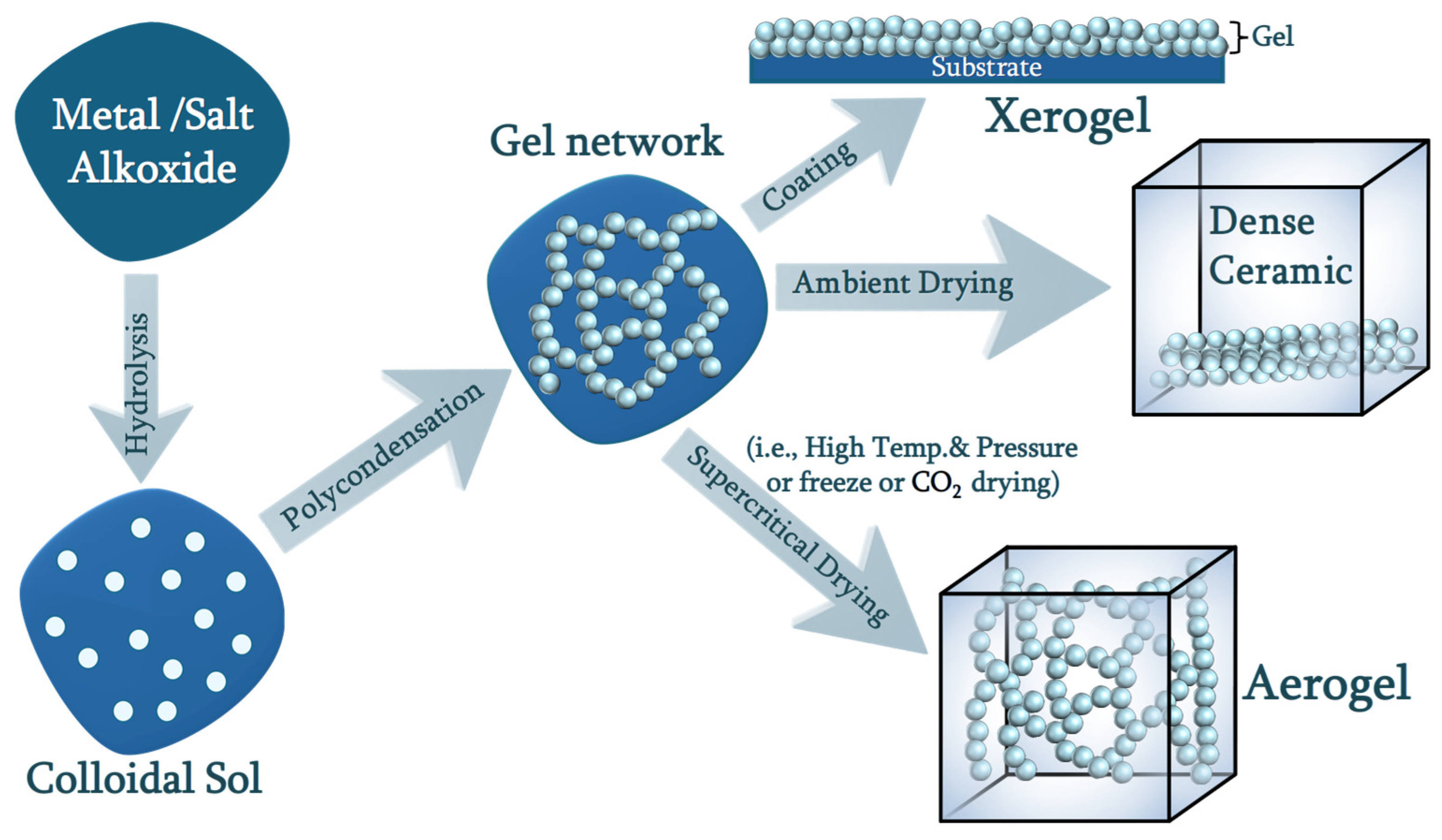
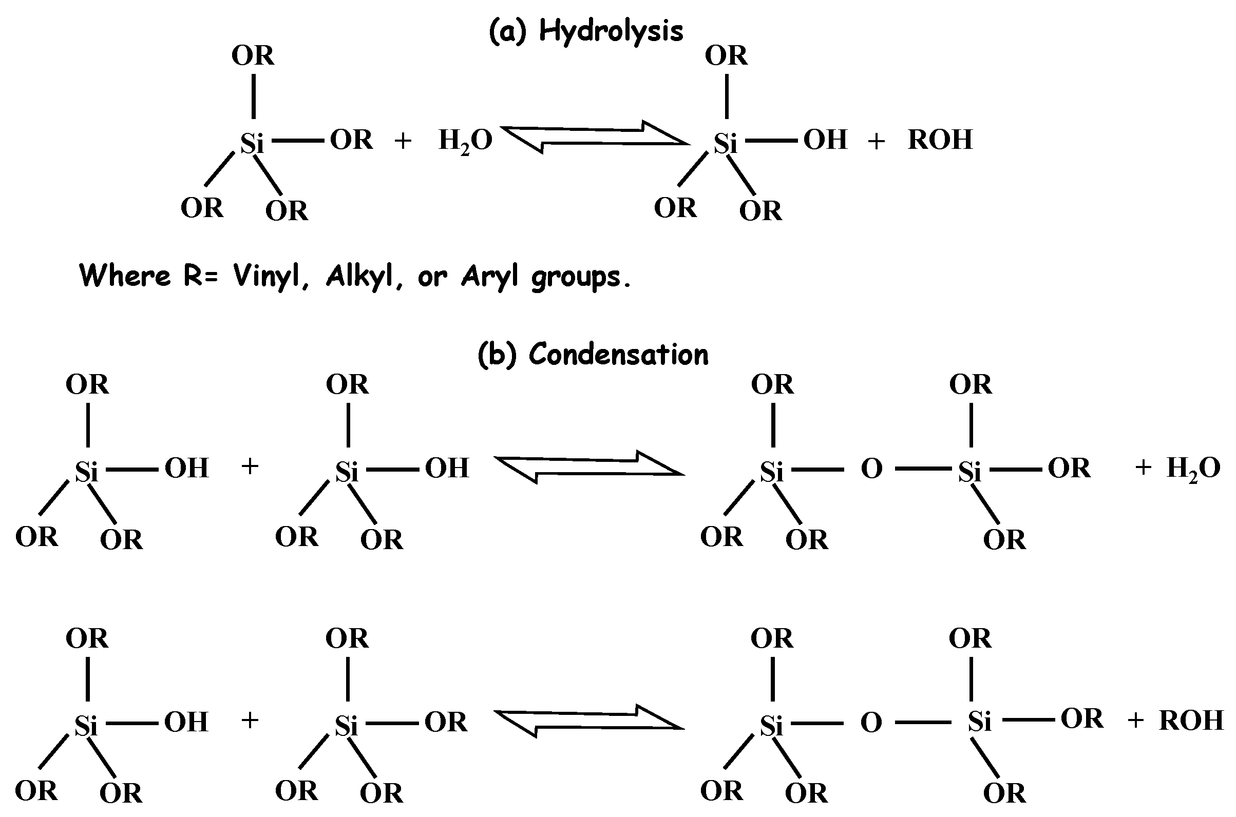
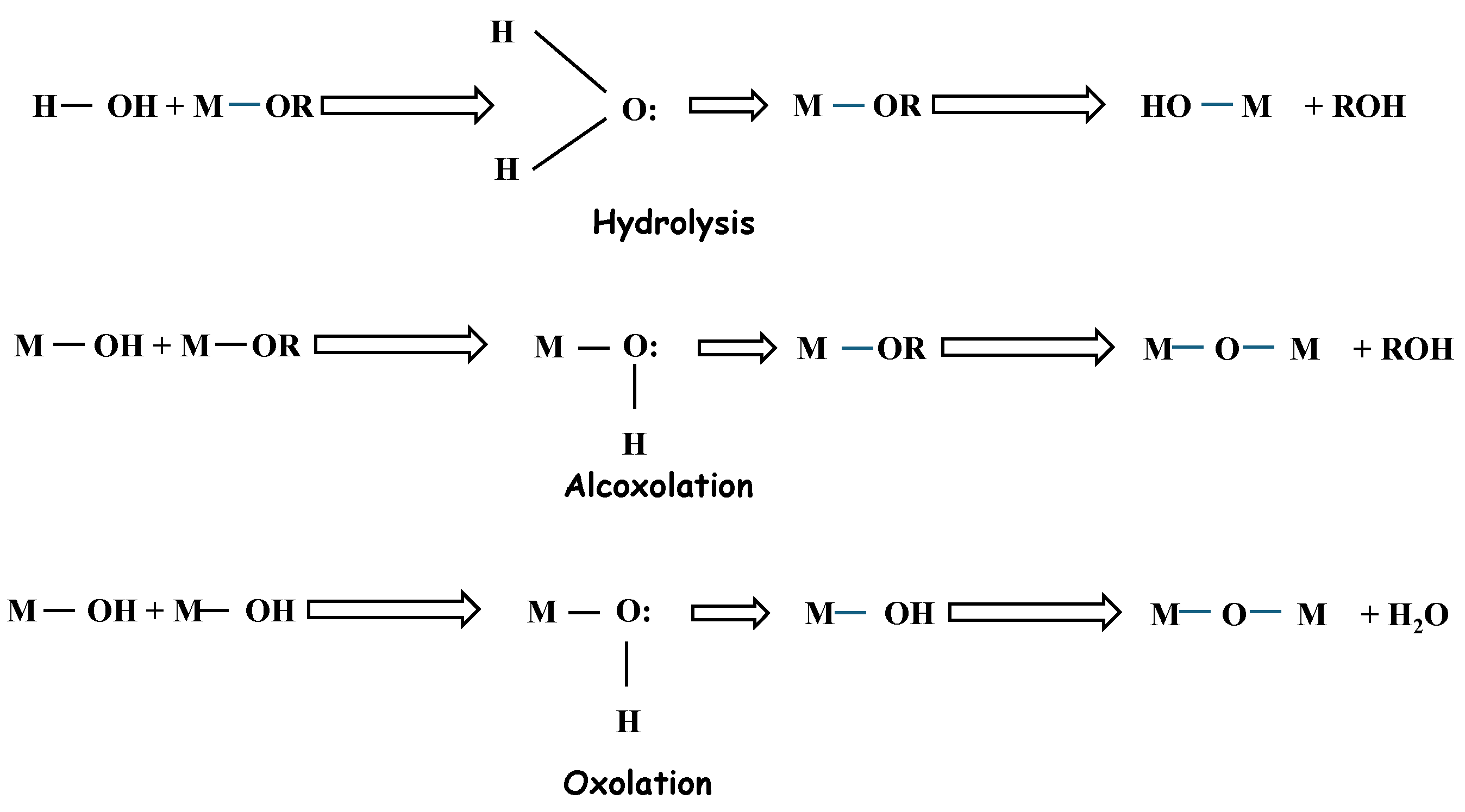
2.1. Chemistry of Sol–Gel
2.2. Synthesis of Silica Aerogel
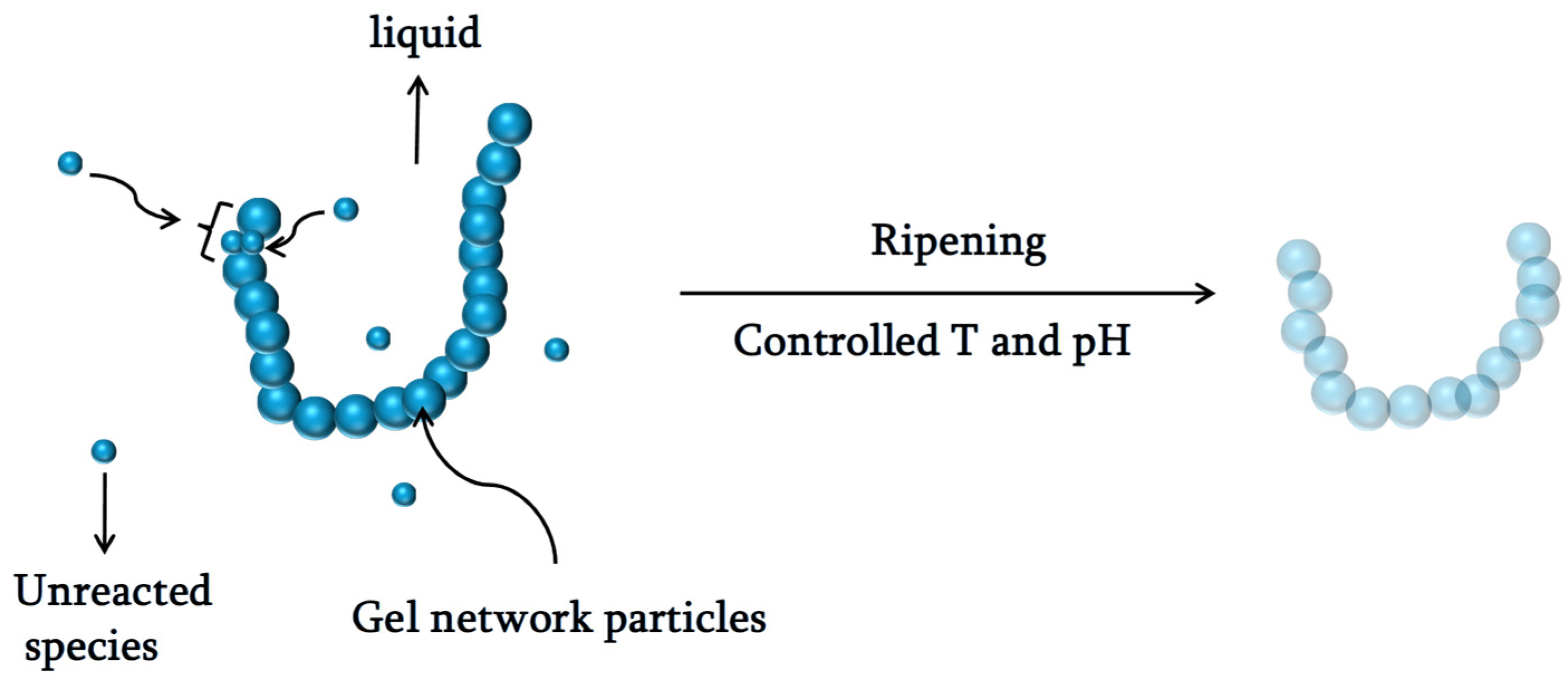
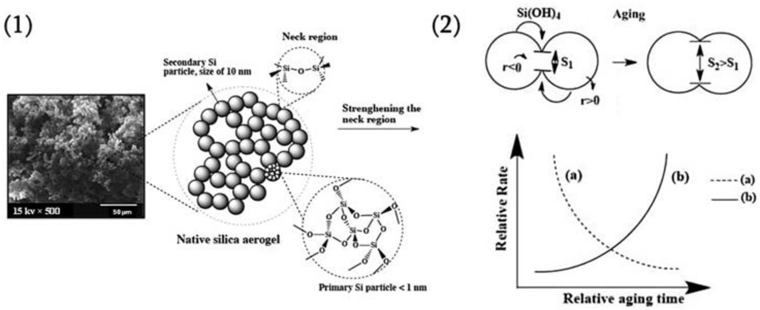
3. Aging
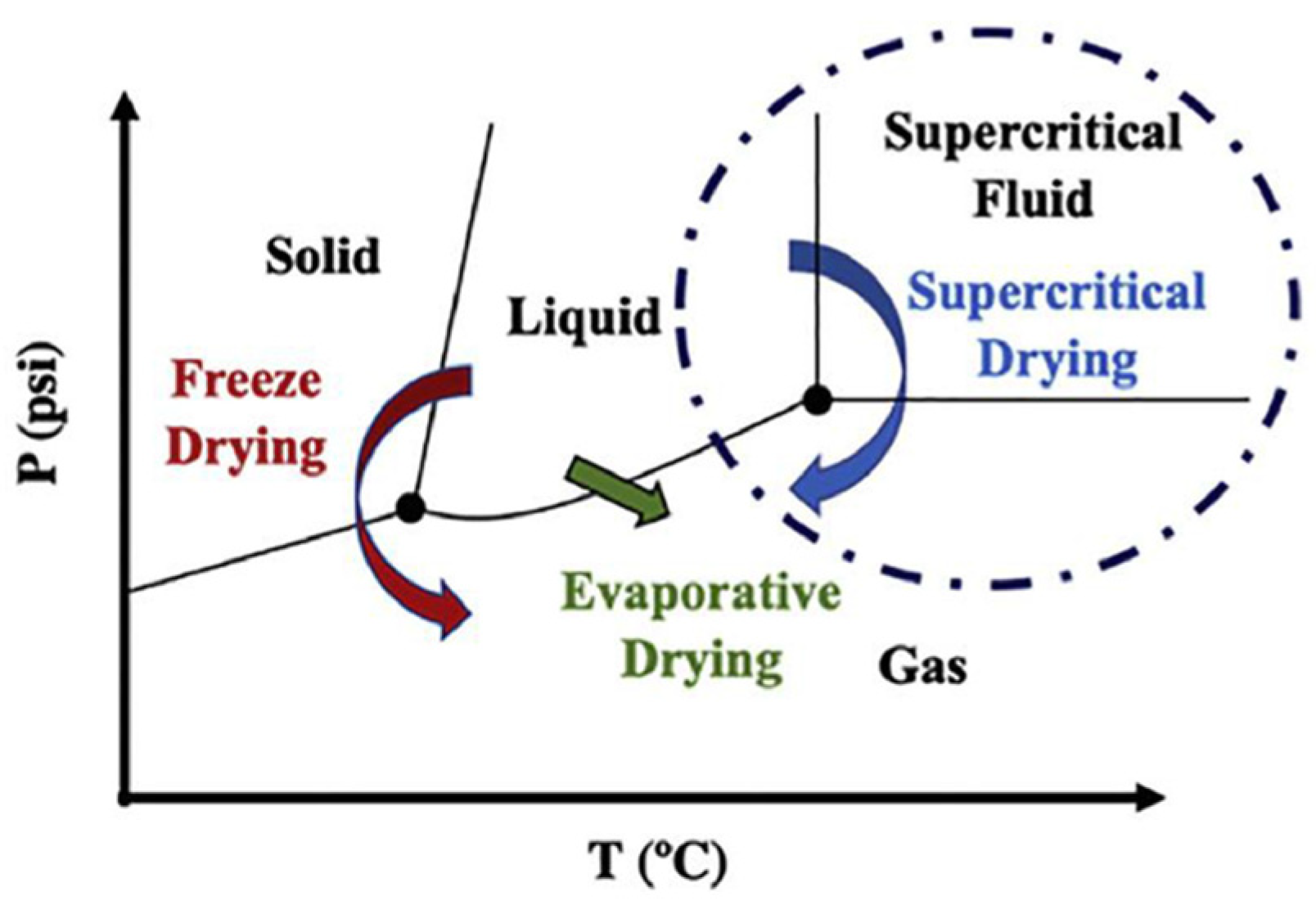
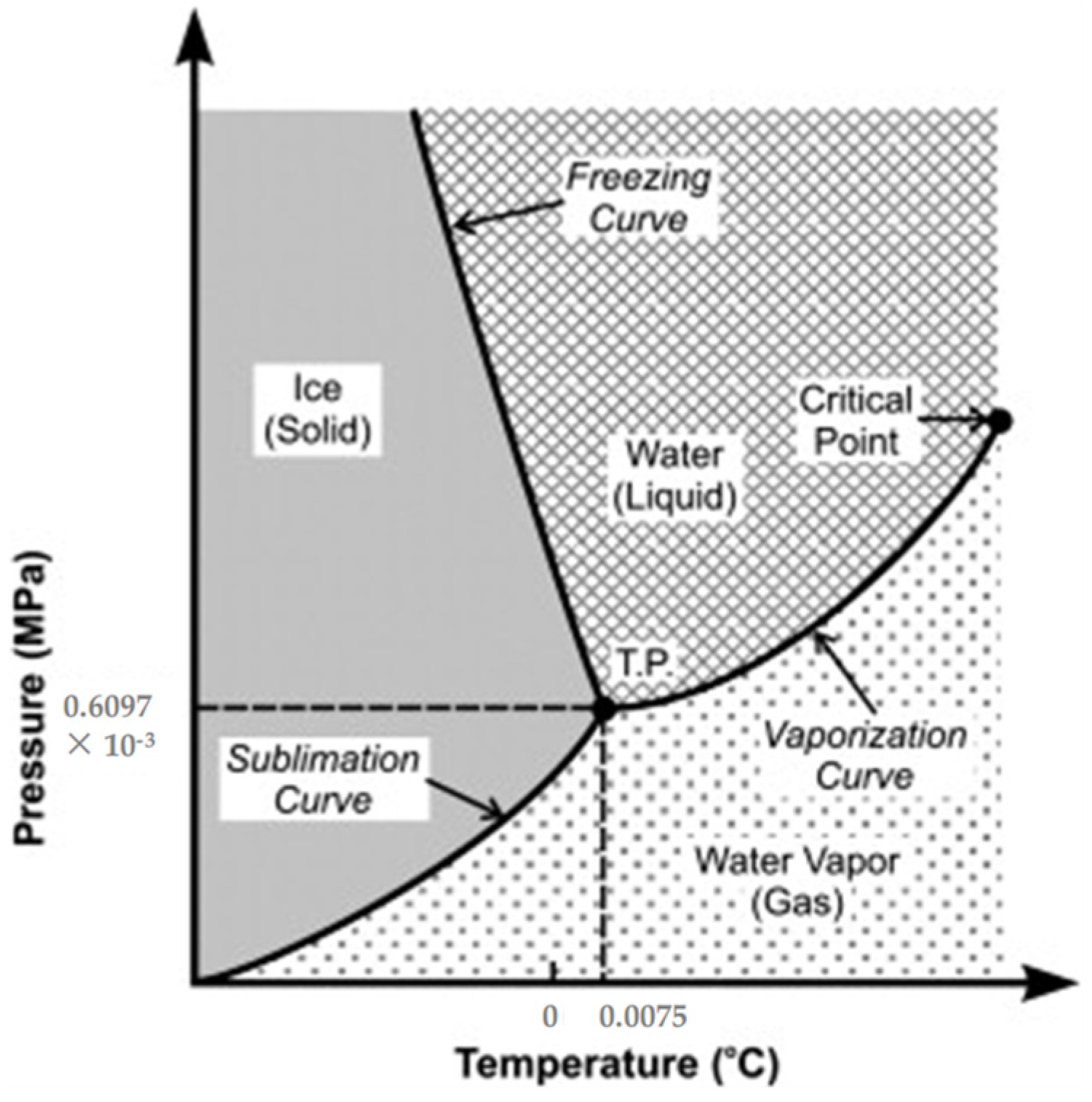
4. Drying
4.1. Evaporation
4.2. Ambient Pressure
4.3. Supercritical Drying
4.4. Freeze-Drying
4.5. Vacuum Drying
5. Properties of the Silica Aerogel
5.1. Transparency Property
5.2. Thermal Property
5.3. Mechanical Property
6. Mechanism of the Network in the Gel
7. Fundamentals of Catalysis
7.1. Catalysis
7.1.1. Electrocatalyst to Produce Hydrogen
7.1.2. Water Electrolysis
7.1.3. The Basic Concept of Electrochemical Water Splitting
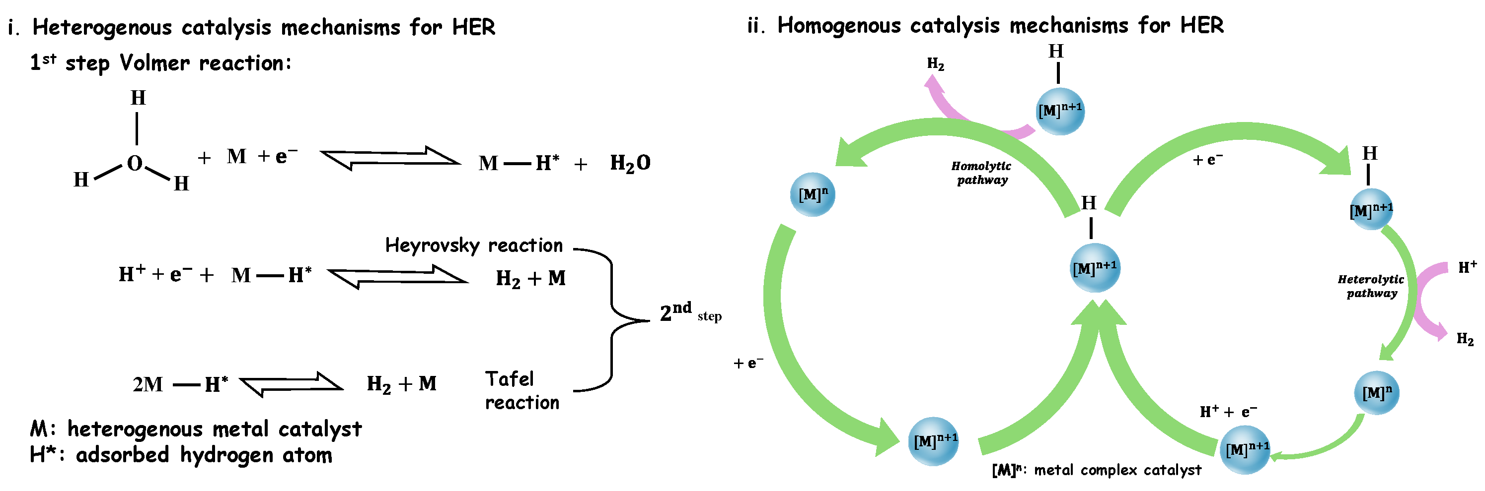
7.1.4. Hydrogen Evolution Reaction (HER)
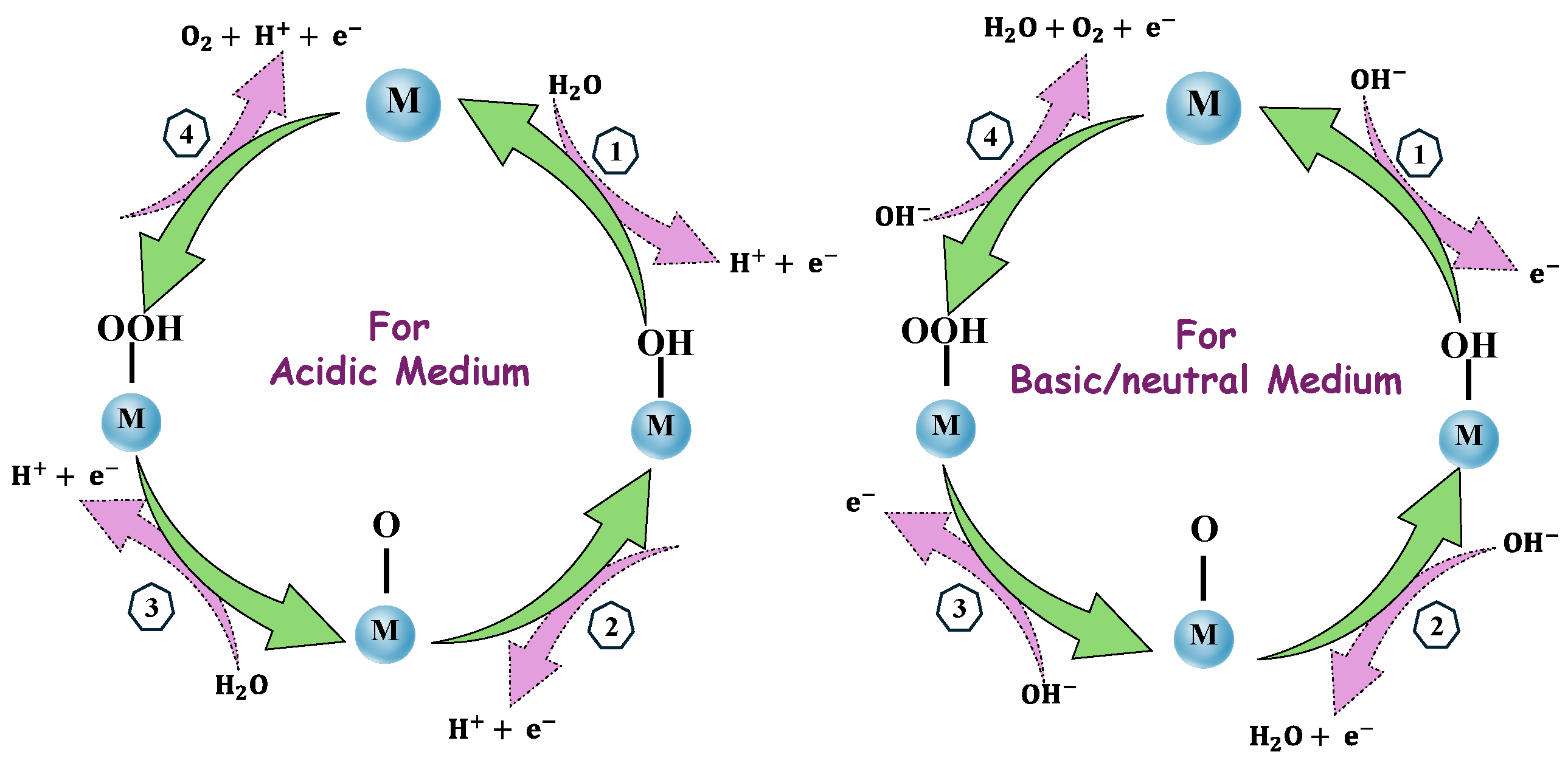
7.1.5. Oxygen Evolution Reaction (OER)
8. Aerogel as Catalyst
8.1. Aerogel as an Electrocatalyst
8.1.1. Silica Aerogel with Catalyst Hydrogen Generation
8.1.2. Factors Affecting Electrocatalysts
8.1.3. Overpotential
8.1.4. Tafel Slope and Current Density
8.1.5. Faraday Efficiency
8.1.6. Turnover Frequency (TOF)
8.1.7. Stability
8.1.8. Activity Descriptors for Silica-Based Aerogels in Hydrogen Generation via Water Splitting
- I.
- Surface Area and Porosity: The maximum active site exposure enables reactant diffusion in the silica aerogels because of high surface area and linked porosity. The percentage of total porosity, pore size distribution, and specific surface area is calculated using Brunauer–Emmett–Teller (BET) analysis.
- II.
- Hydrophilicity and Surface Functionalization: The interactions of water and catalytic activity change with the degree of surface hydroxylation or modification with functional groups (e.g., -OH, -NH2) and can be identified by the contact angle, zeta potential, X-ray photoelectron spectroscopy (XPS)-based hydroxyl group measurement.
- III.
- Electronic Band Structure: The silica aerogel has specific band gap energy that is responsible for how much light is adsorbed by the aerogel in the photocatalytic water splitting. The analysis in conduction and valence band edges is investigated using Mott–Schottky analysis as well as bandgap energy characterized by UV-visible diffuse reflectance spectroscopy (UV-Vis DRS).
- IV.
- Charge Carrier Dynamics and Photocatalytic Efficiency: The effective separation and transfer of photogenerated charge carriers determine hydrogen generation as well as photocatalytic efficiency. Analysis for evaluating recombination includes photoluminescence (PL) intensity; for charge lifetime, transient absorption spectroscopy; for measuring charge transfer resistance, electrochemical impedance spectroscopy (EIS).
- V.
- Stability and Reusability: The aerogels’ long-term stability and recyclability are responsible for the aqueous and oxidative systems, which guarantee useful applicability. Structural integrity via TEM/SEM can be assessed after the reaction, and weight loss can be calculated through TGA measurement.
- VI.
- Metal/Oxide Doping Effects: Metal/oxide doping dopants, like TiO2 [77], Fe [78], Co [79], and MoS2 [80], can increase catalytic activity and enable charge separation. The elemental composition examined using XPS and EDS, oxidation state calculated by Operando X-ray absorption near-edge structure (XANES), extended X-ray absorption fine structure (EXAFS), and local atomic structure described by Raman spectroscopy are represented by characterizations.
9. Aerogel with Plasma Treatment

| Sr. No. | Material | Reactive Gases | Non-Reactive Gases | Advantages | Reference |
|---|---|---|---|---|---|
| 1 | SiO2 film | O2, H2, N2 | He, Ar | Dielectric current ↑ Leakage current ↑ Thickness (O2 > N2 > Ar > He ≅H2) | [82] |
| 2 | SiO2 film | O2 (Si/O/C) | - | Thickness of film ↓ (900–700 ± 10 nm) | [85] |
| 3 | Mesoporous silica thin film | H2, O2 | - | Leakage current ↑ H2 = 3.6 ×10⁻⁶ A/cm2 O2 = 1.17 ×10⁻⁴ A/cm2 | [83] |
| 4 | Amorphous Silica Nanoparticles | N2, O2 | - | Specific surface area = 124 − 420 m2/g Low Thermal Conductivity = 0.00014 W/mK | [86] |
| 5 | Nanoporous Silica thin films | O2, H2, NH3 | - | Dielectric constant density below 1 × 10⁻⁷ A/cm2C | [87] |
10. Silica Aerogel as Open Cell
11. Aerogel as Adsorbent for Dye
12. Conclusions and Outlook
Author Contributions
Funding
Institutional Review Board Statement
Informed Consent Statement
Data Availability Statement
Conflicts of Interest
References
- Sonu, S.S.; Rai, N.; Chauhan, I. Multifunctional Aerogels: A Comprehensive Review on Types, Synthesis and Applications of Aerogels. J. Sol-Gel Sci. Technol. 2023, 105, 324–336. [Google Scholar] [CrossRef]
- Parale, V.G.; Kim, T.; Choi, H.; Phadtare, V.D.; Dhavale, R.P.; Kanamori, K.; Park, H.H. Mechanically Strengthened Aerogels through Multiscale, Multicompositional, and Multidimensional Approaches: A Review. Adv. Mater. 2024, 36, 2307772. [Google Scholar] [CrossRef] [PubMed]
- Alwin, S.; Sahaya Shajan, X. Aerogels: Promising Nanostructured Materials for Energy Conversion and Storage Applications. Mater. Renew. Sustain. Energy 2020, 9, 7. [Google Scholar] [CrossRef]
- Akhter, F.; Soomro, S.A.; Inglezakis, V.J. Silica Aerogels; a Review of Synthesis, Applications and Fabrication of Hybrid Composites. J. Porous Mater. 2021, 28, 1387–1400. [Google Scholar] [CrossRef]
- Almeida, C.M.R.; Ghica, M.E.; Durães, L. An Overview on Alumina-Silica-Based Aerogels. Adv. Colloid Interface Sci. 2020, 282. [Google Scholar] [CrossRef]
- Malakooti, S.; Zhao, E.; Tsao, N.; Bian, N.; Soni, R.U.; ud Doulah, A.S.; Sotiriou-Leventis, C.; Leventis, N.; Lu, H. Synthesis of Aerogel Foams through a Pressurized Sol-Gel Method. Polymer 2020, 208, 122925. [Google Scholar] [CrossRef]
- Huang, C.; Cheng, X.; Chen, B.; Wang, J.; Dai, Y.; Situ, Y.; Huang, H. Preparation of Aerogel-like Silica Foam with the Hollow-Sphere-Based 3D Network Skeleton by the Cast-in Situ Method and Ambient Pressure Drying. Nano Lett. 2022, 22, 9290–9296. [Google Scholar] [CrossRef] [PubMed]
- Maleki, H.; Durães, L.; Portugal, A. An Overview on Silica Aerogels Synthesis and Different Mechanical Reinforcing Strategies. J. Non Cryst. Solids 2014, 385, 55–74. [Google Scholar] [CrossRef]
- Al-Hamamre, Z.; Karimzadeh, Z.; Ji, S.; Choi, H.; Maleki, H. Aerogels-Inspired Based Photo and Electrocatalyst for Water Splitting to Produce Hydrogen. Appl. Mater. Today 2022, 29, 101670. [Google Scholar] [CrossRef]
- Khan, N.R.; Sharmin, T.; Bin Rashid, A. Exploring the Versatility of Aerogels: Broad Applications in Biomedical Engineering, Astronautics, Energy Storage, Biosensing, and Current Progress. Heliyon 2024, 10, e23102. [Google Scholar] [CrossRef]
- Ahmad, S.; Ahmad, S.; Sheikh, J.N. Silica Centered Aerogels as Advanced Functional Material and Their Applications: A Review. J. Non Cryst. Solids 2023, 611, 122322. [Google Scholar] [CrossRef]
- Randall, J.P.; Meador, M.A.B.; Jana, S.C. Tailoring Mechanical Properties of Aerogels for Aerospace Applications. ACS Appl. Mater. Interfaces 2011, 3, 613–626. [Google Scholar] [CrossRef] [PubMed]
- Sharma, S.; Kaur, A. Various Methods for Removal of Dyes from Industrial Effluents—A Review. Indian J. Sci. Technol. 2018, 11, 1–21. [Google Scholar] [CrossRef]
- Vishnu, D.; Dhandapani, B.; Authilingam, S.; Sivakumar, S.V. A Comprehensive Review of Effective Adsorbents Used for the Removal of Dyes from Wastewater. Curr. Anal. Chem. 2022, 18, 255–268. [Google Scholar] [CrossRef]
- Bal, G.; Thakur, A. Distinct Approaches of Removal of Dyes from Wastewater: A Review. Mater. Today Proc. 2021, 50, 1575–1579. [Google Scholar] [CrossRef]
- Al-Amrani, W.A.; Hanafiah, M.A.K.M.; Mohammed, A.H.A. A Comprehensive Review of Anionic Azo Dyes Adsorption on Surface-Functionalised Silicas. Environ. Sci. Pollut. Res. 2022, 29, 76565–76610. [Google Scholar] [CrossRef]
- Sarvalkar, P.D.; Vadanagekar, A.S.; Karvekar, O.S.; Kumbhar, P.D.; Terdale, S.S.; Thounaojam, A.S.; Kolekar, S.S.; Vhatkar, R.S.; Patil, P.S.; Sharma, K.K.K. Thermodynamics of Azo Dye Adsorption on a Newly Synthesized Titania-Doped Silica Aerogel by Cogelation: A Comparative Investigation with Silica Aerogels and Activated Charcoal. ACS Omega 2023, 8, 13285–13299. [Google Scholar] [CrossRef]
- Shuang, C.; Li, P.; Li, A.; Zhou, Q.; Zhang, M.; Zhou, Y. Quaternized Magnetic Microspheres for the Efficient Removal of Reactive Dyes. Water Res. 2012, 46, 4417–4426. [Google Scholar] [CrossRef]
- Saiz, J.; Bringas, E.; Ortiz, I. Functionalized Magnetic Nanoparticles as New Adsorption Materials for Arsenic Removal from Polluted Waters. J. Chem. Technol. Biotechnol. 2014, 89, 909–918. [Google Scholar] [CrossRef]
- Zhai, Q.Z. Studies of Adsorption of Crystal Violet from Aqueous Solution by Nano Mesocellular Foam Silica: Process Equilibrium, Kinetic, Isotherm, and Thermodynamic Studies. Water Sci. Technol. 2020, 81, 2092–2108. [Google Scholar] [CrossRef]
- Meléndez-Ortiz, H.I.; Puente-Urbina, B.; Mercado-Silva, J.A.; García-Uriostegui, L. Adsorption Performance of Mesoporous Silicas towards a Cationic Dye. Influence of Mesostructure on Adsorption Capacity. Int. J. Appl. Ceram. Technol. 2019, 16, 1533–1543. [Google Scholar] [CrossRef]
- Vinayakumar, K.; Palliyarayil, A.; Kumar, N.S.; Sil, S. Processing of Aerogels and Their Applications toward CO2 Adsorption and Electrochemical Reduction: A Review. Environ. Sci. Pollut. Res. 2022, 29, 47942–47968. [Google Scholar] [CrossRef]
- Du, A.; Zhou, B.; Zhang, Z.; Shen, J. A Special Material or a New State of Matter: A Review and Reconsideration of the Aerogel. Materials 2013, 6, 941–968. [Google Scholar] [CrossRef] [PubMed]
- Niculescu, A.G.; Tudorache, D.I.; Bocioagă, M.; Mihaiescu, D.E.; Hadibarata, T.; Grumezescu, A.M. An Updated Overview of Silica Aerogel-Based Nanomaterials. Nanomaterials 2024, 14, 469. [Google Scholar] [CrossRef] [PubMed]
- Normal, M.T.; Amor, N.; Ali, A.; Petrik, S.; Coufal, R.; Adach, K.; Fijalkowski, M. Aerogels for Biomedical, Energy and Sensing Applications. Gels 2021, 7, 264. [Google Scholar] [CrossRef]
- Smirnova, I.; Gurikov, P. Aerogel Production: Current Status, Research Directions, and Future Opportunities. J. Supercrit. Fluids 2018, 134, 228–233. [Google Scholar] [CrossRef]
- Sharma, J.; Sheikh, J.; Behera, B.K. Aerogel Composites and Blankets with Embedded Fibrous Material by Ambient Drying: Reviewing Their Production, Characteristics, and Potential Applications. Dry. Technol. 2023, 41, 915–947. [Google Scholar] [CrossRef]
- Danks, A.E.; Hall, S.R.; Schnepp, Z. The Evolution of “sol-Gel” Chemistry as a Technique for Materials Synthesis. Mater. Horiz. 2016, 3, 91–112. [Google Scholar] [CrossRef]
- Sarvalkar, P.D.; Barawkar, S.D.; Karvekar, O.S.; Patil, P.D.; Prasad, S.R.; Sharma, K.K.; Prasad, N.R.; Vhatkar, R.S. A Review on Multifunctional Nanotechnological Aspects in Modern Textile. J. Text. Inst. 2022, 114, 470–487. [Google Scholar] [CrossRef]
- Rashid, A.B.; Shishir, S.I.; Mahfuz, M.A.; Hossain, M.T.; Hoque, M.E. Silica Aerogel: Synthesis, Characterization, Applications, and Recent Advancements. Part. Part. Syst. Charact. 2023, 40, 2200186. [Google Scholar] [CrossRef]
- Banoth, P.; Kandula, C.; Kollu, P. Introduction to Electrocatalysts. ACS Symp. Ser. 2022, 1432, 1–37. [Google Scholar] [CrossRef]
- Aruchamy, G.; Kim, B.K. Recent Trends and Perspectives in Single-Entity Electrochemistry: A Review with Focus on a Water Splitting Reaction. Crit. Rev. Anal. Chem. 2024, 1–17. [Google Scholar] [CrossRef]
- Guzel Kaya, G.; Deveci, H. Synergistic Effects of Silica Aerogels/Xerogels on Properties of Polymer Composites: A Review. J. Ind. Eng. Chem. 2020, 89, 13–27. [Google Scholar] [CrossRef]
- Karamikamkar, S.; Naguib, H.E.; Park, C.B. Advances in Precursor System for Silica-Based Aerogel Production toward Improved Mechanical Properties, Customized Morphology, and Multifunctionality: A Review. Adv. Colloid Interface Sci. 2020, 276, 102101. [Google Scholar] [CrossRef]
- Abebe, A.M.; Soraru, G.D.; Thothadri, G.; Andoshe, D.M.; Zambotti, A.; Ahmed, G.M.S.; Tirth, V.; Algahtani, A. Synthesis and Characterization of High Surface Area Transparent SiOC Aerogels from Hybrid Silicon Alkoxide A Comparison between Ambient Pressure and Supercritical Drying. Materials 2022, 15, 1277. [Google Scholar] [CrossRef] [PubMed]
- Linhares, T.; Pessoa De Amorim, M.T.; Durães, L. Silica Aerogel Composites with Embedded Fibres: A Review on Their Preparation, Properties and Applications. J. Mater. Chem. A 2019, 7, 22768–22802. [Google Scholar] [CrossRef]
- Heinrich, T.; Klett, U.; Fricke, J. Aerogels-Nanoporous Materials Part I: Sol-Gel Process and Drying of Gels. J. Porous Mater. 1995, 1, 7–17. [Google Scholar] [CrossRef]
- El-Naggar, M.E.; Othman, S.I.; Allam, A.A.; Morsy, O.M. Synthesis, Drying Process and Medical Application of Polysaccharide-Based Aerogels. Int. J. Biol. Macromol. 2020, 145, 1115–1128. [Google Scholar] [CrossRef]
- Fijalkowski, M.; Coufal, R.; Ali, A.; Adach, K.; Petrik, S.; Bu, H.; Karl, C.W. Flexible Hybrid and Single-Component Aerogels: Synthesis, Characterization, and Applications. Langmuir 2023, 39, 16760–16775. [Google Scholar] [CrossRef]
- Ettema, R.; Kirkil, G.; Daly, S. Frazil Ice Concerns for Channels, Pump-Lines, Penstocks, Siphons, and Tunnels in Mountainous Regions. Cold Reg. Sci. Technol. 2009, 55, 202–211. [Google Scholar] [CrossRef]
- Faez, T.; Yaghmaee, M.S.; Sarkar, S. The State of Art and Possible New Applications of Nano/Meso Porous Silica Aerogel. Electron. J. Biol. 2005, 1, 76–80. [Google Scholar]
- Parale, V.G.; Lee, K.Y.; Park, H.H. Flexible and Transparent Silica Aerogels: An Overview. J. Korean Ceram. Soc. 2017, 54, 184–199. [Google Scholar] [CrossRef]
- Ji, C.; Zhu, S.; Zhang, E.; Li, W.; Liu, Y.; Zhang, W.; Su, C.; Gu, Z.; Zhang, H. Research Progress and Applications of Silica-Based Aerogels—A Bibliometric Analysis. RSC Adv. 2022, 12, 14137–14153. [Google Scholar] [CrossRef]
- Majeed, S.S.; Othuman Mydin, M.A.; Bahrami, A.; Dulaimi, A.; Özkılıç, Y.O.; Omar, R.; Jagadesh, P. Development of Ultra-Lightweight Foamed Concrete Modified with Silicon Dioxide (SiO2) Nanoparticles: Appraisal of Transport, Mechanical, Thermal, and Microstructural Properties. J. Mater. Res. Technol. 2024, 30, 3308–3327. [Google Scholar] [CrossRef]
- Zhang, X.; Shakeel, M.; Li, B.; Wang, L. Fabrication of Foamed Zinc Oxide-Silica Spheres Coupled with Ag–AgBr for High-Efficiency Photo-Electrocatalytic Overall Water Splitting. Electrochim. Acta 2020, 331, 135369. [Google Scholar] [CrossRef]
- Gurav, J.L.; Jung, I.K.; Park, H.H.; Kang, E.S.; Nadargi, D.Y. Silica Aerogel: Synthesis and Applications. J. Nanomater. 2010, 2010, 409310. [Google Scholar] [CrossRef]
- Gaweł, B.; Gaweł, K.; Øye, G. Sol-Gel Synthesis of Non-Silica Monolithic Materials. Materials 2010, 3, 2815–2833. [Google Scholar] [CrossRef]
- Zhan, W.; Chen, L.; Kong, Q.; Li, L.; Chen, M.; Jiang, J.; Li, W.; Shi, F.; Xu, Z. The Synthesis and Polymer-Reinforced Mechanical Properties of SiO 2 Aerogels: A Review. Molecules 2023, 28, 5534. [Google Scholar] [CrossRef]
- Brinker, C.J.; Scherer, G.W. (Eds.) Sol-Gel Science: The Physics and Chemistry of Sol-Gel Processing; Academic Press: Boston, MA, USA, 2013; 908p. [Google Scholar]
- Aslam, S.; Rani, S.; Lal, K.; Fatima, M.; Hardwick, T.; Shirinfar, B.; Ahmed, N. Electrochemical Hydrogen Production: Sustainable Hydrogen Economy. Green Chem. 2023, 25, 9543–9573. [Google Scholar] [CrossRef]
- Vidas, L.; Castro, R. Recent Developments on Hydrogen Production Technologies: State-of-the-Art Review with a Focus on Green-Electrolysis. Appl. Sci. 2021, 11, 1363. [Google Scholar] [CrossRef]
- Sharma, M.; Pramanik, A.; Bhowmick, G.D.; Tripathi, A.; Ghangrekar, M.M.; Pandey, C.; Kim, B.S. Premier, Progress and Prospects in Renewable Hydrogen Generation: A Review. Fermentation 2023, 9, 537. [Google Scholar] [CrossRef]
- Mohanty, B.; Bhanja, P.; Jena, B.K. An Overview on Advances in Design and Development of Materials for Electrochemical Generation of Hydrogen and Oxygen. Mater. Today Energy 2022, 23, 100902. [Google Scholar] [CrossRef]
- Solanki, R.; Patra, I.; Ahmad, N.; Kumar, N.B.; Parra, R.M.R.; Zaidi, M.; Yasin, G.; Anil Kumar, T.C.; Hussein, H.A.; Sivaraman, R.; et al. Investigation of Recent Progress in Metal-Based Materials as Catalysts toward Electrochemical Water Splitting. J. Environ. Chem. Eng. 2022, 10, 108207. [Google Scholar] [CrossRef]
- Sun, F.; Tang, Q.; Jiang, D.E. Theoretical Advances in Understanding and Designing the Active Sites for Hydrogen Evolution Reaction. ACS Catal. 2022, 12, 8404–8433. [Google Scholar] [CrossRef]
- Gao, C.; Zhang, X.; Zhan, J.; Cai, B. Engineering of Aerogel-Based Electrocatalysts for Oxygen Evolution Reaction. Electrochem. Sci. Adv. 2022, 2, e2100113. [Google Scholar] [CrossRef]
- Anwar, S.; Khan, F.; Zhang, Y.; Djire, A. Recent Development in Electrocatalysts for Hydrogen Production through Water Electrolysis. Int. J. Hydrogen Energy 2021, 46, 32284–32317. [Google Scholar] [CrossRef]
- Yan, Y.; Xia, B.Y.; Zhao, B.; Wang, X. A Review on Noble-Metal-Free Bifunctional Heterogeneous Catalysts for Overall Electrochemical Water Splitting. J. Mater. Chem. A 2016, 4, 17587–17603. [Google Scholar] [CrossRef]
- Miao, L.; Jia, W.; Cao, X.; Jiao, L. Computational Chemistry for Water-Splitting Electrocatalysis. Chem. Soc. Rev. 2024, 53, 2771–2807. [Google Scholar] [CrossRef]
- Raveendran, A.; Chandran, M.; Dhanusuraman, R. A Comprehensive Review on the Electrochemical Parameters and Recent Material Development of Electrochemical Water Splitting Electrocatalysts. RSC Adv. 2023, 13, 3843–3876. [Google Scholar] [CrossRef]
- Pierre, A.C.; Pajonk, G.M. Chemistry of Aerogels and Their Applications. Chem. Rev. 2002, 102, 4243–4265. [Google Scholar] [CrossRef]
- Khan, M.A.; Zhao, H.; Zou, W.; Chen, Z.; Cao, W.; Fang, J.; Xu, J.; Zhang, L.; Zhang, J. Recent Progresses in Electrocatalysts for Water Electrolysis. Electrochem. Energy Rev. 2018, 1, 483–530. [Google Scholar] [CrossRef]
- Zinola, C.F.; Martins, M.E.; Tejera, E.P.; Neves, N.P. Electrocatalysis: Fundamentals and Applications. Int. J. Electrochem. 2012, 2012, 1–2. [Google Scholar] [CrossRef]
- Yu, P.J.; Lee, M.H.; Hsu, H.M.; Tsai, H.M.; Chen-Yang, Y.W. Silica Aerogel-Supported Cobalt Nanocomposites as Efficient Catalysts toward Hydrogen Generation from Aqueous Ammonia Borane. RSC Adv. 2015, 5, 13985–13992. [Google Scholar] [CrossRef]
- Yue, X.; Li, H.; Qiu, Y.; Xiao, Z.; Yu, X.; Xue, C.; Xiang, J. A Facile Synthesis Method of TiO2@SiO2 Porous Core Shell Structure for Photocatalytic Hydrogen Evolution. J. Solid State Chem. 2021, 300, 122250. [Google Scholar] [CrossRef]
- Somakli, S.; Butun Sengel, S. Hydro(Solvo)Thermal-Supported Nano/Microparticle-Doped Silica Aerogels: Synthesis, Characterization and Catalyst Applications for H2 Production. Silicon 2023, 15, 7069–7083. [Google Scholar] [CrossRef]
- Joshi, M.M.; Labhsetwar, N.K.; Parwate, D.V.; Rayalu, S.S. Efficient Photocatalytic Hydrogen Generation by Silica Supported and Platinum Promoted Titanium Dioxide. Mater. Res. Bull. 2013, 48, 3545–3552. [Google Scholar] [CrossRef]
- Domínguez, M.; Taboada, E.; Idriss, H.; Molins, E.; Llorca, J. Fast and Efficient Hydrogen Generation Catalyzed by Cobalt Talc Nanolayers Dispersed in Silica Aerogel. J. Mater. Chem. 2010, 20, 4875–4883. [Google Scholar] [CrossRef]
- Gores, H.J.; Schweiger, H. Encyclopedia of Applied Electrochemistry; Springer: New York, NY, USA, 2014; ISBN 9781441969965. [Google Scholar]
- Wu, H.; Huang, Q.; Shi, Y.; Chang, J.; Lu, S. Electrocatalytic Water Splitting Mechanism and Electrocatalyst Design. Nano Res. 2023, 16, 9142–9157. [Google Scholar] [CrossRef]
- Krishnan, A.; Ajay, R.; Anakha, J.; Namboothiri, U.S.K. Understanding Defect Chemistry in TMOS Involved Electrocatalytic OER; an Analysis for Advancement. Surf. Interfaces 2022, 30, 101942. [Google Scholar] [CrossRef]
- Xu, C.; Zhang, M.; Yin, X.; Gao, Q.; Jiang, S.; Cheng, J.; Kong, X.; Liu, B.; Peng, H.Q. Recent Advances in Two-Dimensional Nanomaterials as Bifunctional Electrocatalysts for Full Water Splitting. J. Mater. Chem. A 2023, 11, 18502–18529. [Google Scholar] [CrossRef]
- Ďurovič, M.; Hnát, J.; Bouzek, K. Electrocatalysts for the Hydrogen Evolution Reaction in Alkaline and Neutral Media. A Comparative Review. J. Power Sources 2021, 493. [Google Scholar] [CrossRef]
- Wen, N.; Jiao, X.; Xia, Y.; Chen, D. Electrocatalysts for the Oxygen Evolution Reaction: Mechanism, Innovative Strategies, and Beyond. Mater. Chem. Front. 2023, 7, 4833–4864. [Google Scholar] [CrossRef]
- Inocêncio, C.V.M.; Holade, Y.; Morais, C.; Kokoh, K.B.; Napporn, T.W. Electrochemical Hydrogen Generation Technology: Challenges in Electrodes Materials for a Sustainable Energy. Electrochem. Sci. Adv. 2023, 3, e2100206. [Google Scholar] [CrossRef]
- Guan, D.; Wang, B.; Zhang, J.; Shi, R.; Jiao, K.; Li, L.; Wang, Y.; Xie, B.; Zhang, Q.; Yu, J.; et al. Hydrogen Society: From Present to Future. Energy Environ. Sci. 2023, 16, 4926–4943. [Google Scholar] [CrossRef]
- Sun, F.; Xu, D.; Xie, Y.; Liu, F.; Wang, W.; Shao, H.; Ma, Q.; Yu, H.; Yu, W.; Dong, X. Tri-Functional Aerogel Photocatalyst with an S-Scheme Heterojunction for the Efficient Removal of Dyes and Antibiotic and Hydrogen Generation. J. Colloid Interface Sci. 2022, 628, 614–626. [Google Scholar] [CrossRef]
- Sait Izgi, M.; Ece, M.Ş.; Kazici, H.Ç.; Şahin, Ö.; Onat, E. Hydrogen Production by Using Ru Nanoparticle Decorated with Fe3O4@SiO2–NH2 Core-Shell Microspheres. Int. J. Hydrogen Energy 2020, 45, 30415–30430. [Google Scholar] [CrossRef]
- Yu, J.; Li, Z.; Liu, T.; Zhao, S.; Guan, D.; Chen, D.; Shao, Z.; Ni, M. Morphology Control and Electronic Tailoring of CoxAy (A = P, S, Se) Electrocatalysts for Water Splitting. Chem. Eng. J. 2023, 460, 141674. [Google Scholar] [CrossRef]
- Lu, D.; Fan, H.; Kondamareddy, K.K.; Yu, H.; Wang, A.; Hao, H.; Li, M.; Shen, J. Highly Efficient Visible-Light-Induced Photocatalytic Production of Hydrogen for Magnetically Retrievable Fe3O4@SiO2@MoS2/g-C3N4 Hierarchical Microspheres. ACS Sustain. Chem. Eng. 2018, 6, 9903–9911. [Google Scholar] [CrossRef]
- Kim, H.R.; Park, H.H. The Effect of Ar+ Ion Bombardment on SiO2 Aerogel Film. Jpn. J. Appl. Phys. 1998, 37, 6955–6958. [Google Scholar] [CrossRef]
- Kim, J.J.; Park, H.H.; Hyun, S.H. Effects of Plasma Treatment on SiO2 Aerogel Film Using Various Reactive (O2, H2, N2) and Non-Reactive (He, Ar) Gases. Thin Solid Film. 2000, 377–378, 525–529. [Google Scholar] [CrossRef]
- Jung, S.B.; Park, H.H. Improvement of Electrical Properties of Surfactant-Templated Mesoporous Silica Thin Films by Plasma Treatment. Thin Solid Film. 2006, 506–507, 360–363. [Google Scholar] [CrossRef]
- Jung, S.B.; Park, H.H.; Kim, H. The Role of Vacuum Ultraviolet in H 2 Plasma Treatment on SiO 2 Aerogel Film. Appl. Surf. Sci. 2003, 216, 156–162. [Google Scholar] [CrossRef]
- Kim, H.R.; Park, H.H.; Hyun, S.H.; Yeom, G.Y. Effect of O2 Plasma Treatment on the Properties of SiO2 Aerogel Film. Thin Solid Film. 1998, 332, 444–448. [Google Scholar] [CrossRef]
- Pan, G.T.; Chong, S.; Yang, T.C.K.; Yang, Y.L.; Arjun, N. Surface Modification of Amorphous SiO2 Nanoparticles by Oxygen-Plasma and Nitrogen-Plasma Treatments. Chem. Eng. Commun. 2016, 203, 1666–1670. [Google Scholar] [CrossRef]
- Cho, A.T.; Tsai, T.G.; Yang, C.M.; Chao, K.J.; Pan, F.M. Plasma Treatments of Molecularly Templated Nanoporous Silica Films. Electrochem. Solid-State Lett. 2001, 4. [Google Scholar] [CrossRef]
- Wu, H.; Zhang, H.; Zhang, G.; Liu, J.; Liu, Z.; Du, F. Study on Preparation and Performance of Advanced Aerogel Foamed Concrete with Ultra-Light Aerogel. Constr. Build. Mater. 2023, 366, 130166. [Google Scholar] [CrossRef]
- Kayal, U.; Mohanty, B.; Bhanja, P.; Chatterjee, S.; Chandra, D.; Hara, M.; Kumar Jena, B.; Bhaumik, A. Ag Nanoparticle-Decorated, Ordered Mesoporous Silica as an Efficient Electrocatalyst for Alkaline Water Oxidation Reaction. Dalt. Trans. 2019, 48, 2220–2227. [Google Scholar] [CrossRef]
- Nawaz, K.; Schmidt, S.J.; Jacobi, A.M. Effect of Catalyst and Substrate on the Moisture Diffusivity of Silica-Aerogel-Coated Metal Foams. Int. J. Heat Mass Transf. 2014, 73, 634–644. [Google Scholar] [CrossRef]
- Huo, W.L.; Zhang, X.; Hu, Z.; Chen, Y.; Wang, Y.; Yang, J. Silica Foams with Ultra-Large Specific Surface Area Structured by Hollow Mesoporous Silica Spheres. J. Am. Ceram. Soc. 2019, 102, 955–961. [Google Scholar] [CrossRef]
- Zhao, M.; Wang, Y.; Liu, Z.; Cui, D.; Bian, X. Properties of Immobilized Laccase on Mesostructured Cellular Foam Silica and Its Use in Dye Decolorization. J. Macromol. Sci. Part A Pure Appl. Chem. 2011, 48, 447–453. [Google Scholar] [CrossRef]
- Zhai, Q.Z.; Dong, Y. Adsorption Properties of Aqueous Methylene Blue on Mesocellular Foam Silica: Equilibrium, Kinetic, Isotherm, and Thermodynamic Characterization. Instrum. Sci. Technol. 2019, 47, 467–484. [Google Scholar] [CrossRef]
- Liu, Q.; Liu, Y.; Zhang, Z.; Wang, X.; Shen, J. Adsorption of Cationic Dyes from Aqueous Solution Using Hydrophilic Silica Aerogel via Ambient Pressure Drying. Chin. J. Chem. Eng. 2020, 28, 2467–2473. [Google Scholar] [CrossRef]
- Shi, W.; Tao, S.; Yu, Y.; Wang, Y.; Ma, W. High Performance Adsorbents Based on Hierarchically Porous Silica for Purifying Multicomponent Wastewater. J. Mater. Chem. 2011, 21, 15567–15574. [Google Scholar] [CrossRef]

| Synthesis | Aerogels | Advantages | Disadvantages |
|---|---|---|---|
| Sol-gel | Inorganic aerogel, Hybrid Aerogels, and composite aerogel | Monoliths formed, Pores size diameter 1 μm, 3D network, cost effective and easy method. | Low crystallinity of gels, amorphous, Hydrolysis and condensation are fast, time consuming. |
| Self-assembly | Oxide aerogels, Graphene based, metallic aerogel | Structure with large and complex network, Crystalline aerogels obtained | Assembly of aerogel structure is uncontrollable |
| Emulsion | Inorganic oxide aerogel, Polymer | Spherical shaped micro aerogel can be formed by analysing and refining | Aerogels are usually impure as the elimination of emulsifier is difficult |
| Template | Graphene, Polymer and Functional Aerogels | Crystalline aerogel with high quality and Intricate formations exhibiting desirable resolutions | Structure of aerogel collapses after the elimination of the template |
| Epoxy | Oxide aerogel | Control of properties and composition, formation of composite of metal materials is possible | Composed aerogels have amorphous nature, prolonged time period |
| 3D printing | Polymer and hybrid aerogels | Macroporous structure, design of intricate structures is possible | Printing procedures, expensive, solution viscosity maintenance, post-processing (chemical and/or heat) needed to give mechanical strength and structural integrity |
| Sr. No. | Property | Open Cell Foam | Closed Cell Foam |
|---|---|---|---|
| 1. | Density | Lightweight | High Density |
| 2. | Barrier | Air | Air and Moisture |
| 3. | Cost | Less Expensive | Expensive |
| 4. | Flexibility and Durability | Soft | Hard |
| 5. | R value (insulation’s ability to resist) | High | Low |
| Sr. No | Property | Value | Comments |
|---|---|---|---|
| 1. | Thermal Conductivity | 0.017–0.021 (Wm−1K−1) | High internal surface area Continuous porous geometry |
| 2. | Bulk Density | 0.003 ± 0.500 (g/cm3) | Empty spaces are filled by air |
| 3. | Inner Surface Area | 100–1600 (m2g−1) | High porosity |
| 4. | Porosity | 80–99.8 (%) | High |
| 5. | Mean Pore diameter | 20–150 (nm) | Nanoscale dimension |
| 6. | Refraction Index | 1.0–1.05 | Very low |
| 7. | Thermal tolerance | >500 °C | At first shrinkage occurs from 500 °C, increasing with an increase in temperature |
| 8. | Modulus of Elasticity | 0.002–100 (MPa) | Low |
| 9. | Dielectric Constant | ~1.1 | Very low |
| 10. | Sound velocity | 20–800 (ms−1) | Low |
| Sr. No. | Material | Synthesis | Pore Diameter (nm) | Pore Volume (cm3 g−1) | Dye Adsorbed | Dye Adsorbed | Adsorption Isotherm and Process | Reference |
|---|---|---|---|---|---|---|---|---|
| 1 | Hierarchically porous silica micro-foam with sulfonic acid (SO3H-HSM) | Sol–gel | 13.78 | - | Rhodamine B, Fuchsin basic, Neutral red | Rhodamine B, Fuchsin basic, Neutral red | Freundlich Isotherm | [95] |
| 2 | Mesocellular silica foam | Hydrothermal | 9 | 1.36 | Methylene Blue | Methylene Blue | Freundlich and quasi second order | [93] |
| 3 | Mesoporous silica (MCM-41) | Hydrothermal | 2.4 | 0.733 | Toluidine blue O | Toluidine blue O | Freundlich and quasi second order | [21] |
| 4 | Mesocellular silica foam | Hydrothermal | 13.44 | - | Crystal violet | Crystal violet | Freundlich and quasi second order | [20] |
Disclaimer/Publisher’s Note: The statements, opinions and data contained in all publications are solely those of the individual author(s) and contributor(s) and not of MDPI and/or the editor(s). MDPI and/or the editor(s) disclaim responsibility for any injury to people or property resulting from any ideas, methods, instructions or products referred to in the content. |
© 2025 by the authors. Licensee MDPI, Basel, Switzerland. This article is an open access article distributed under the terms and conditions of the Creative Commons Attribution (CC BY) license (https://creativecommons.org/licenses/by/4.0/).
Share and Cite
Vadanagekar, A.; Lapcik, L.; Kvitek, L.; Lapcikova, B. Silica Aerogels as a Promising Vehicle for Effective Water Splitting for Hydrogen Production. Molecules 2025, 30, 1212. https://doi.org/10.3390/molecules30061212
Vadanagekar A, Lapcik L, Kvitek L, Lapcikova B. Silica Aerogels as a Promising Vehicle for Effective Water Splitting for Hydrogen Production. Molecules. 2025; 30(6):1212. https://doi.org/10.3390/molecules30061212
Chicago/Turabian StyleVadanagekar, Apurva, Lubomir Lapcik, Libor Kvitek, and Barbora Lapcikova. 2025. "Silica Aerogels as a Promising Vehicle for Effective Water Splitting for Hydrogen Production" Molecules 30, no. 6: 1212. https://doi.org/10.3390/molecules30061212
APA StyleVadanagekar, A., Lapcik, L., Kvitek, L., & Lapcikova, B. (2025). Silica Aerogels as a Promising Vehicle for Effective Water Splitting for Hydrogen Production. Molecules, 30(6), 1212. https://doi.org/10.3390/molecules30061212