2.1. Growth of Protein Crystals inside Pores
Firstly, and most importantly, there is a considerable difference between protein crystal growth in the confined pore space and growth in the open space outside the pore. Inside a pore, the growth of a crystal merely leads to an increase in volume, whereas the crystal surface, which is exposed to the destructive action of the water molecules, does not change in size (the reason being that the size of the pore hardly changes at a molecular distance). Hence, importantly, the destructive efficacy of the water molecules with respect to the protein crystal in the pore does not change. On the other hand, the growth of a crystal outside the pore leads to a simultaneous increase in both its volume and surface; indeed, the larger the crystal surface, the more intensive the destructive action of the water molecules.
The growth of a 3D protein crystal in a pore starts by attaching molecules to a previously formed, completely stable 2D crystal nucleus (for the latter, see Ref. [
13]). The first protein molecules impinging on the nucleus are strongly and sufficiently connected, provided they are simultaneously bound to the pore wall and to the existing stable 2D nucleus. Then, additional molecules arrive, and they are bound even more strongly at kink sites formed by the first molecules and the lower crystal layer. The result of such a growth process is a complete protein layer of monomolecular thickness, deposited onto the pre-existing stable 2D crystal nucleus. When reiterated several times, this process leads to the transformation of the stable 2D crystal nucleus into a 3D protein crystal.
Since, as shown in Ref. [
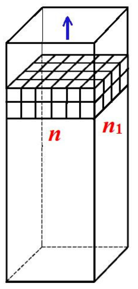
13], real non-regularly shaped pore orifices yield theoretical results that are very similar to those obtained with idealized pore shapes, we expect that the conclusions reached in this paper for regular pore shapes are generally valid. Therefore, we start the quantitative analysis of the formation of a 3D protein crystal in a pore by considering the simplest crystal lattice, the so-called Kossel crystal (a simple cubic symmetry crystal, constituted by small cubes held together by equal forces, as shown in
Figure 1). Importantly, the formation of a 3D protein crystal from a pre-existing 2D completely stable nucleus inside the pore is an energetically driven process. The primary cause of this is the substantial increase in cohesive crystal energy Δ
Gv, resulting from the increased number of intermolecular bonds between the two protein layers of monomolecular thickness (whereas the crystal destructive energy Δ
Gs remains the same). A stabilizing role is also played by the interaction of the protein molecules with the walls of the pore. Surrounded by four pore walls, the crystal inside it is substantially more stable than the 3D crystals formed (and growing) on foreign surfaces, as can be seen in [
14]. However, the bonding of the protein molecules to the pore walls depends on the type of protein and porous material. All this makes the calculation of the balance between the crystal cohesive and destructive energies very difficult. To circumvent this problem,
only for the growth of protein crystals inside pores, the bonding to pore walls (which is weaker than the bonding between the protein molecules in the crystal) is not considered. The price paid for this simplification is that the results are merely indicative.
Counting only the number of intermolecular bonds between the first and second crystal layers, we obtain
nn1 bonds, where
n and
n1 denote the number of molecules at the edges of the Kossel crystal, as in
Figure 1. To these, we must add the (
n − 1)(
n1 − 1) bonds that account for the intermolecular bonds within the layer (obviously the same as in the first layer of monomolecular thickness). As a result, the increase in the number of intermolecular bonds is:
, i.e., the growing crystal becomes more than twice as strong.
More generally, the increase in Δ
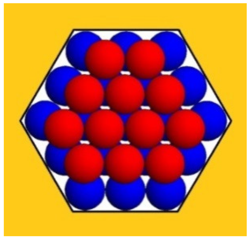
Gv depends on the type of crystal lattice. Because the Kossel crystal has a relatively low-density packing, the increase in the number of intermolecular bonds in the Kossel crystal will be compared with that in the closest-packed crystal lattices (e.g., see
Figure 2); we hope that this comparison sheds additional light on the spontaneous growth of protein crystals in pores.
Figure 2 depicts a second monomolecular layer of a hexagonal close-packed (HCP) crystal that is deposited onto the completely stable nucleus (the blue balls). This is a ditrigonal layer, which is a little smaller than the first (hexagonal) layer. Therefore, it does not touch the pore walls (meaning there is no interaction between the protein molecules and the walls of the pore). However, each molecule in the ditrigonal layer (like in any close-packed crystal structure) interacts with three molecules underneath it—meaning that the energy needed for stripping-off one overlaying layer is three times larger. Consequently, this energy contribution overcompensates for the absence of interaction between protein molecules and pore walls (see
Table 1 below).
The third layer in HCP crystals is also hexagonal; therefore, it touches the pore wall. However, most important is the fact that the destructive energy ΔGs, which tends to tear up the crystal, is always equal to the number of molecules in the uppermost (ditrigonal or hexagonal) crystal layers, which are exposed to the destructive action of the water molecules. (Evidently, only the molecules on the crystal surface interact with the water.).
The numbers of molecules and the numbers of intermolecular bonds in the closest-packed (ditrigonal and hexagonal) monolayers are known from crystallographic equations. Using these, we can perform numerical calculations of the relations between Δ
Gv and Δ
Gs for crystals with one, two, three etc., layers. In doing so, we denote by
λ the number of molecules in the longer ditrigonal crystal edges (which equals the number of molecules in the hexagonal layer beneath it, as seen in
Figure 2). As such, the number of molecules in the ditrigonal monolayers denoted by
Z is:
Equation (1) gives Z = 12, 27, 48, 75... for λ = 3, 4, 5, 6..., respectively.
And the number
z of molecules in hexagonal layers, the edge lengths of which are determined from the number
L of molecules in them, is:
Equation (2) gives z = 19, 37, 61, 91... for L = 3, 4, 5, 6..., respectively.
The number of bonds Δ
Gvd in ditrigonal layers is given by the following equation:
where
λ corresponds to the longer edge of the ditrigonal layer.
The number of bonds Δ
Gvh in the hexagonal crystal layer is obtained from the crystallographic formula:
With
being the destructive energy per bond, the destructive energies Δ
Gs are, respectively:
and:
The results of the calculations performed by means of these equations are shown in
Table 1, where the bonding energy is denoted by
. Since, again, the interactions with the pore walls are not considered, these results are indicative only (and serve merely for comparison with the results of the Kossel crystals). A direct comparison shows that, in both cases, the growth of the protein crystals in pores is increasingly stimulated as the pores become wider. However, it is also evident that the wider the pore, the less important the positive effect of the capillary walls becomes. Thus, there is an optimal range of pore orifice widths.
The sharp increase in crystal stability with the thickening of the HCP crystal shown in
Table 1, although somewhat mitigated for larger crystals, suggests that the growth of protein crystals in pores is, in general, an energetically driven process.
The fourth crystal layer, being again ditrigonal, has a smaller number of protein molecules exposed to the destructive action of the water molecules. This strengthens our conclusion that the growth of protein crystals in pores occurs by consecutive deposition of layers of monomolecular thickness and, being energetically favored, it is ceaseless. Therefore, there is no need to form a three-dimensional crystal nucleus to continue the growth of the protein crystal inside the pore.
Finally, it is worth noting that point defects (vacancies and interstitials) increase the conformational entropy and thus stabilize the crystals formed inside the pores [
13]. On the other hand, such small crystals hardly tolerate the formation of dislocations; it is therefore more probable that dislocations arise in the crystals at later growth stages outside the pores.
2.2. Spontaneous Growth of the Protein Crystals outside the Pores
Because the volume of the protein crystal in the pore is negligible in comparison with the volume outside it, the latter growth stage is of prime importance for the diffraction ability of the protein crystal. Therefore, this stage of protein crystal growth deserves special attention. Importantly, when the protein crystal reaches the orifice of the pore, it starts growing at a protein concentration which is lower to that inside the pore: its growth is therefore slowed down. Additionally, the slower the crystal grows, the more perfect it is. The reason for this is that fewer impurities are incorporated by the slow-growing crystal, which leads to fewer defects in its lattice, meaning an improved diffraction quality [
6]. Therefore, by lowering the supersaturation under which the crystals nucleate and grow (compared to the supersaturation needed for conventional crystal nucleation), the use of porous nucleants contributes to the further success of X-ray protein crystallography. Our experiments confirmed this theoretical suggestion [
7].
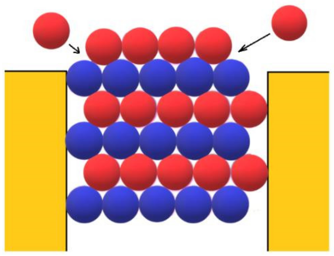
Let us consider the growth of protein crystals outside the pores in more detail. Firstly, the open space outside the pore is already advantageous for growing 3D protein crystals. As they are expanding laterally, those crystals are fed from more directions; thus, the effect of the reduced protein concentration outside the pore is somewhat mitigated. Secondly, because the binding energy between the two monomolecular protein layers is added to the binding energy between the molecules in the newly deposited monomolecular layer (see
Figure 3), the binding energy Δ
Gv is substantially increased. Therefore, we could suggest that the wider the pore orifice, the more energetically favored the growth of the crystal outside it. However, a very wide pore would approach the limit of a flat surface. On the other hand, since the pore opening is reached and the protein molecules enter the pore with the same probability with which they reach an equally large flat surface area, the narrower the pore orifices, the less accessible they are [
12]. Additionally, the narrower the pore, i.e., the smaller the crystal nucleus, the higher the supersaturation required for its formation. As already mentioned, however, excessively high supersaturation can hardly result from the synergistic effects of diffusion in the confined pore spaces and protein adsorption on pore walls. Thus, we conclude again that there is an optimal range of pore orifice widths. Considering all the above arguments, we concluded that pores narrower than about 1 μm can accumulate enough protein to induce crystal nucleation [
12].
To approach this issue quantitatively, we consider a crystal in a pore to have the same volume as a completely stable homogeneously formed crystal nucleus, which is expected to grow steadily [
15,
16]. The size of the latter is determined using the equilibration between the cohesive energy that maintains the integrity of a crystalline cluster and the destructive energy that tends to tear it up, i.e., the change in Gibbs free energy is
(recalling that the completely stable homogeneously formed crystal nucleus is 50% larger than the 3D critical crystal nucleus.).
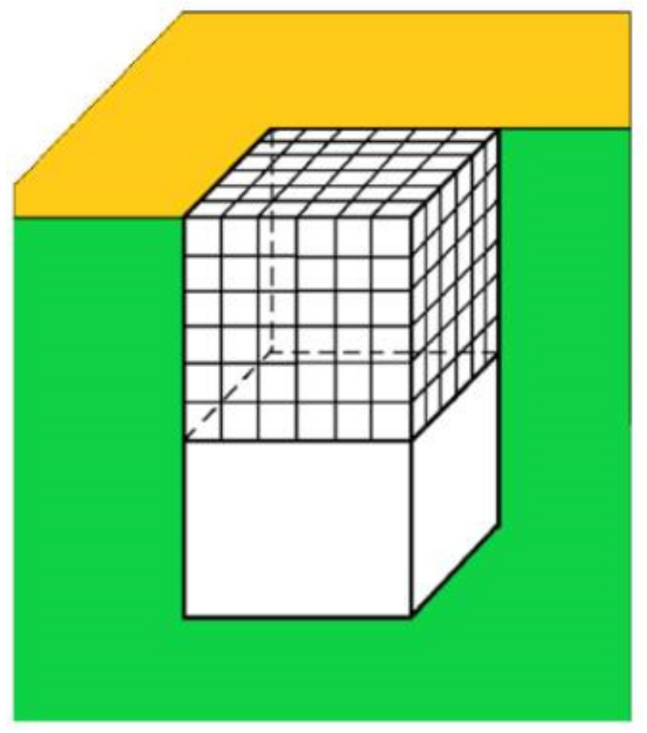
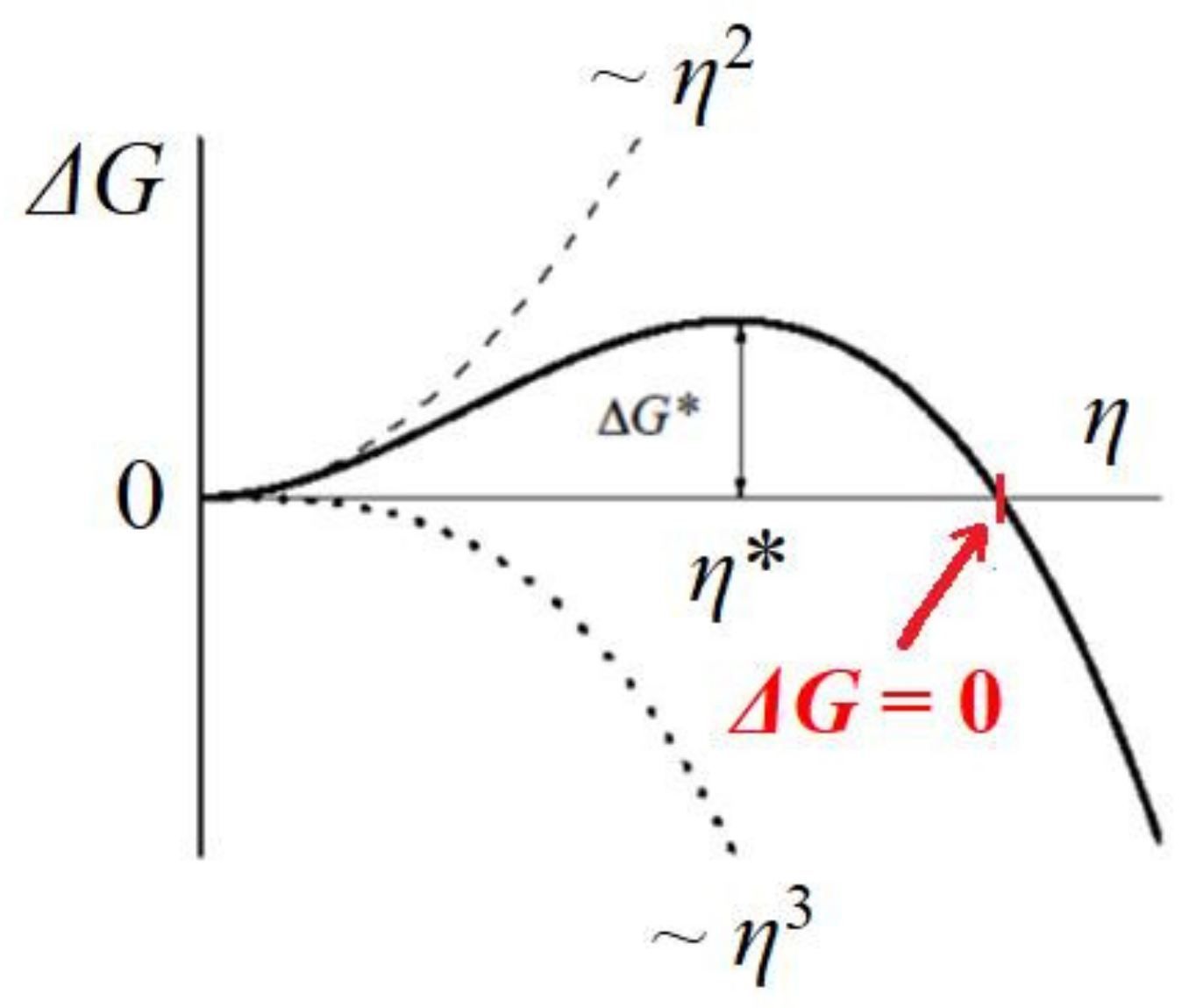
Crystals in pores can have diverse shapes, but a calculation of the value of the supersaturation needed for the growth of the crystal outside the pore can be obtained by looking at a cubic crystal that has just reached the pore opening (see
Figure 4). The change in Gibbs free energy Δ
G (see
Figure 5), which is required for crystal formation, is a sum of two terms: (1) the free energy gain resulting from the transfer of molecules from the supersaturated mother phase into the crystal (which is proportional to its volume, the so-called ‘volume term’); and (2) the free energy penalty, imposed due to the formation of the new interface (i.e., a ‘surface term’, which is proportional to the total area of the crystal). As such, we write the change in Δ
G needed for the homogeneous formation of a cubic crystal constituted by
η molecules:
where
S is the total surface of the nucleus, and
δ the edge length of the crystal building block;
γc [erg/cm
2] is the surface free energy.
For crystallization in solutions, the supersaturation is the driving energy for crystal nucleation; kB is the Boltzmann constant; T is the absolute temperature; c is the actual concentration; and ce is the equilibrium with respect to an “infinitely” large crystal (as usual, activity coefficients equal to 1 are assumed).
Thus, for a completely stable and homogeneously formed cubic crystal nucleus, the equilibration between cohesive energy Δ
Gv and destructive energy Δ
Gs (i.e.,
, see
Figure 5) in Equation (7) gives:
where Δ
μv denotes the supersaturation needed for homogeneous formation of the completely stable crystal nucleus.
Dividing Equation (8) by
η, we obtain:
Of prime importance in our consideration is the fact that a large part of the surface of the crystal in the pore is protected from the destructive action of the water molecules—the latter can attack only a small part of its surface, the one that protrudes from the pore. Thus, the vulnerable surface of the crystal is reduced sixfold, and for the completely stable crystal face at the pore opening (at
), Equation (7) becomes:
where Δ
μp is the supersaturation at which the cubic crystal shown in
Figure 4 is expected to grow steadily.
Again, dividing Equation (10) by
η, we obtain the value of this supersaturation:
Comparing Equation (9) with Equation (11), we see that Δ
μp is six times lower than Δ
μv. In other words, the unimpeded growth outside the pore orifice of the cubic crystal face (shown in
Figure 4) of size
is secured by supersaturation equal to Δ
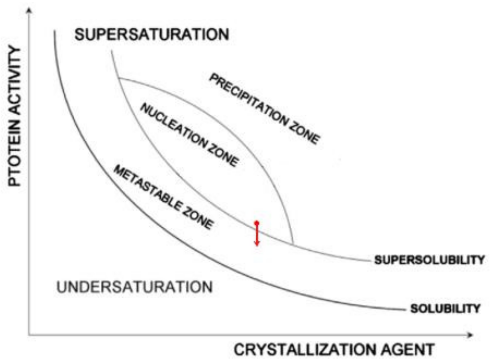
μp. Recalling that protein crystals nucleate in pores at moderate supersaturations (which are achievable in pores due to the synergistic diffusion–adsorption effect that arises from pore space confinement and interaction with pore walls), we suggest that the protein crystal nucleation in pores takes place in the nucleation zone, but close to the super-solubility curve (see the red point in
Figure 6). Consequently, it is most likely that Δ
μp is below the super-solubility curve, i.e., already in the metastable zone (see the red arrow in
Figure 6).
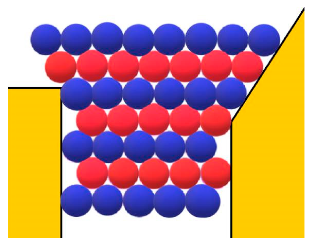
However, besides the stabilization of the crystal face at the pore orifice, which results from the protection of a considerable part of the crystal surface from the destructive action of water molecules, there are additional factors which promote its unimpeded growth. Apart from the open space outside the pore, another factor enabling the growth of the crystal outside it can be the adsorption of protein molecules on the surface of porous material. The shape of the pore orifice plays an important role in this respect: While angular pore openings (assumed by Page and Sear [
18] and seen in
Figure 3) hardly promote the adsorption of protein molecules, real ones (such as the one shown in
Figure 7) that are generally devoid of sharp angles are more suitable for protein adsorption. Performing a random walk, some protein molecules arrive at the crystal face, which is level with the pore opening (see the two red balls at both sides of the pore orifice, approaching as shown by the arrows in
Figure 3). However, they are not attached firmly enough to enable the lateral growth of the crystal outside the pore (the molecules in
Figure 3 are attached to only two molecules of the crystal; for the closest-packed crystals especially, this is insufficient). More suitable in this respect are pore openings such as the one shown in
Figure 7; the reason being that, in contrast to the case shown in
Figure 3, the molecules on the right side of the crystal in
Figure 7 also interact with the inclined surface of the pore opening itself. Thus, instead of only two intermolecular connections of energy
ψb, the impinging molecules bind firmly enough. The connection energy
Eb of the peripheral row of length
λ is:
where
ψ is the adhesion energy of a single protein molecule to the pore material.
Although neglected in [
18], the adhesion energy
ψ is a significant factor contributing to the unimpeded growth of the protein crystal outside the pore; because larger molecules can contact the solid surface at more sites, the adsorption of protein molecules at such surfaces is strong even when affinity is very moderate [
19]. In conclusion, the protein crystal grows outside the pore orifice without the need for 3D nucleation.
2.3. Experimental: Diffraction Quality of Protein Crystals Grown by Using Porous Materials
It is well known that the nucleation of crystals requires much higher supersaturation than is sufficient for their growth. The initial high supersaturation will, however, cause a rapid growth of crystals in which case, as already mentioned, the crystals will incorporate a larger number of impurities, which in turn cause defects. Persisting in the grown crystals, these defects deteriorate their diffraction quality. Hence, to grow more perfect crystals, the time of rapid growth must be shortened as much as possible. With that end in view, the stages of crystal nucleation and growth are sometimes separated, and the high supersaturation that was needed for the initiation of crystal nucleation is lowered during the subsequent growth stage. Usually, such an experimental approach yields better crystals. However, the choice of the exact moment at which to lower the supersaturation depends on the experimenter’s experience, and/or is determined by trial and error.
The important practical advantage of porous nucleants is that by using them, the separation of the nucleation and growth stages becomes superfluous. The reason for this is that only protein concentrations in the metastable zone are applied for growing protein crystals, i.e., the supersaturation is already lowered before inserting the porous nucleants. (Indeed, nucleants are only added in conditions that are known from preliminary experiments to provide insufficient supersaturation to yield crystals). In contrast, supersaturations above the super-solubility curve, which are necessary for the additional nucleation of 3D crystals outside the pore, are never used.
Our data for the actual diffraction of proteins on heterogeneous solid nucleants are reported here. Another porous material has been successfully tested as a protein crystal nucleant: molecularly imprinted polymers (MIPs). It should, however, be noted that the pores in the MIPs are too small (of the size of one, or possibly very few, protein molecules); therefore, no growth inside such pores is possible. Thus, this part of the theory does not apply to the MIPs, which function via a different mechanism of specific molecular affinity. However, the MIPs do decrease the supersaturation that is needed for protein crystal nucleation. Thus, the protein crystals grow under a lower supersaturation, and according to the theoretical expectation, they should be of a better diffraction quality. This theoretical expectation has also been confirmed by our experiments with MIPs, where six out of eight proteins tested under metastable versus higher supersaturation conditions (which were otherwise identical) yielded better diffracting crystals [
8,
10].
Diffraction data have previously been obtained for three target macromolecules (two proteins and one modified cyclodextrin), all of which required improved diffraction in order to determine their structure (
Table 2).
- 1.
Crystals of the C1 domain of the human cardiac myosin-binding protein-C (MyBP-C), obtained on buckypaper (made from an aggregate of single-walled carbon nanotubes and surfactant Triton X-100), diffracted to a maximum resolution of 1.6 Å (more typically in the 2.0–2.2 Å range). This is far superior to the best crystals obtained using standard techniques, which only diffracted to 3.0 Å [
7]. The dominant pore size in the buckypaper was 9 nm. The crystals grew at metastable conditions in the trials with porous material (10 mg/mL protein in 50 mM NaCl and 20 mM Tris pH 7.0, equilibrated by vapor diffusion against a reservoir solution of 18% polyethylene glycol (PEG) of mean MW 3350 and HEPES buffer, pH 7.3). The conventionally grown crystals were obtained from 20% PEG reservoir solutions [
7]. Importantly, in all cases, the crystals in the drops containing nucleant were single, i.e., not in clusters that may have appeared if repeated nucleation of novel 3D crystals outside the pore had occurred.
- 2.
Crystals of InHr2 were obtained in the presence of bioglass at metastable conditions as well as at ‘borderline metastable’ conditions, i.e., conditions that gave visible crystals overnight in the presence of bioglass, but only after 6 days in the absence of porous material (10 mg/mL protein equilibrated against a reservoir solution of 11% PEG of mean MW 3350, 0.1 M imidazole at pH 7.0 and 75 mM MgCl2). The best of these crystals, obtained from the latter conditions, diffracted to 3.2 Å, in comparison to ca. 5 Å for routinely obtained crystals at higher PEG concentrations.
- 3.
Crystals of the cyclodextrin derivative per(6-guanidino-6-deoxy)-γCD (gguan) that were obtained at metastable conditions in the presence of bioglass diffracted to better than 1.08 Å, whereas all X-rayed crystals routinely grown in standard, conventionally optimized conditions, diffracted to 1.3 Å at best. This improvement in resolution enabled the determination of this unusual structure [
20].
Two model proteins were also crystallized with and without bioglass as part of the present study, using known crystallization conditions (see
Section 4 and
Table 2).
- 1.
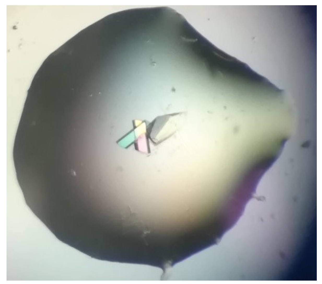
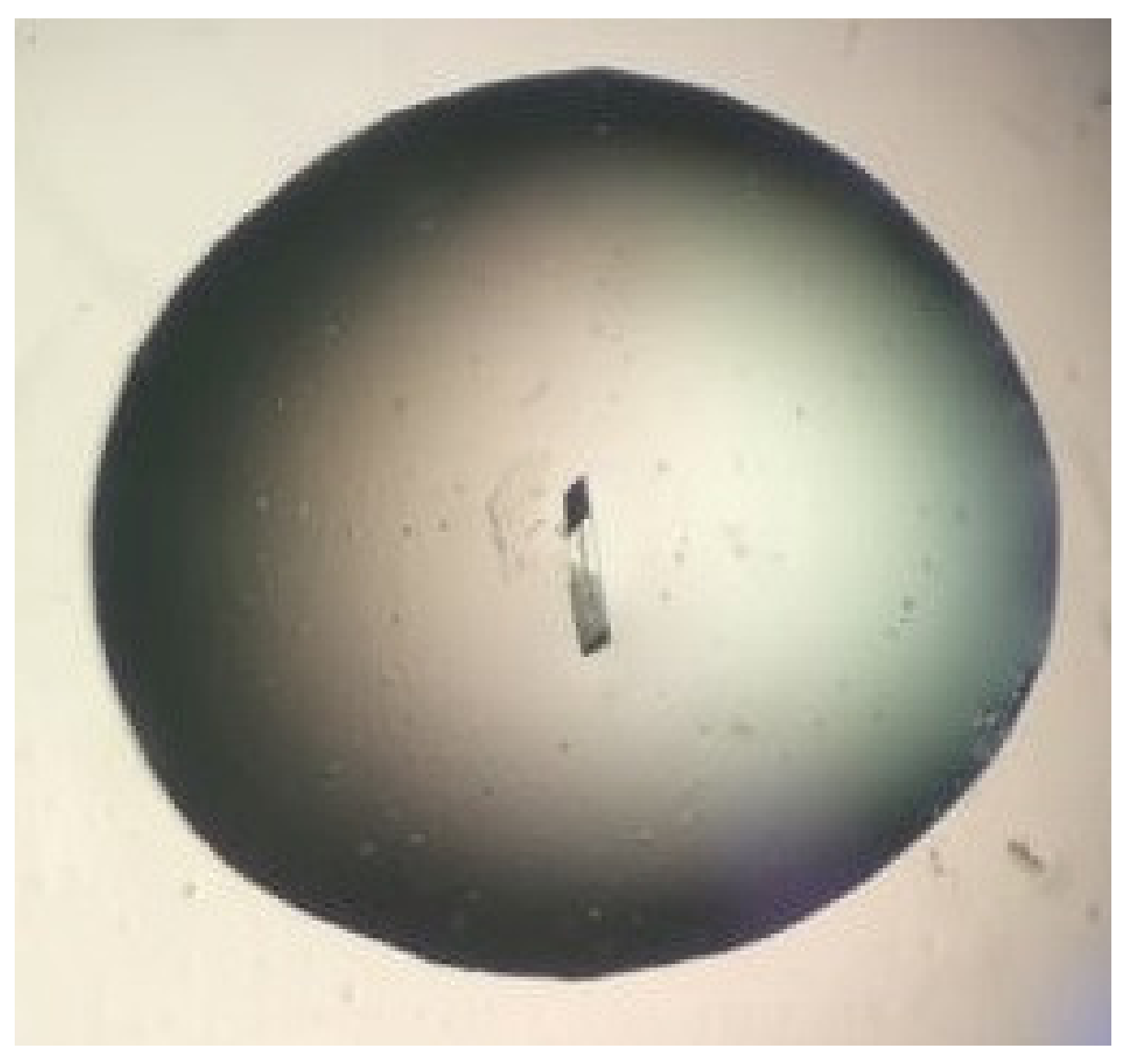
Bovine α-chymotrypsin at metastable conditions (20 mg/mL protein in 25 mM NaOAc pH 4.8, equilibrated against several ammonium sulfate concentrations in the range 0.8–1.3 M ammonium sulfate in the same buffer) yielded medium-sized crystals in the presence of bioglass (and none in the controls). Most crystals were in contact with the bioglass grains (
Figure 8). All trials (bioglass and controls) yielded much smaller crystals at higher supersaturations.
- 2.
Bovine ribonuclease A at metastable conditions (12 mg/mL protein in 10 mM sodium citrate pH 5.0, equilibrated against 24–27% (
w/
v) PEG of mean MW 4000 and 50 mM of the same buffer) yielded small crystals in the presence of bioglass (and none in the controls). At a higher supersaturation (32% PEG), larger crystals of a very similar size and morphology were obtained both with and without bioglass, though the crystals grew appreciably faster in the presence of bioglass (
Figure 9). The best crystal grown in the presence of bioglass diffracted to 2.8 Å versus 3.1 Å for the best crystal grown without bioglass.
To be completely convinced of the porous material’s ability to induce the formation of crystalline nuclei, we used controls in each crystallization trial. While crystals were observed in the samples containing porous nucleants, the controls set up under exactly the same conditions, but without addition of nucleant, were crystal-free. Undeniably, this is completely convincing evidence that the porous material acted as a nucleant.


