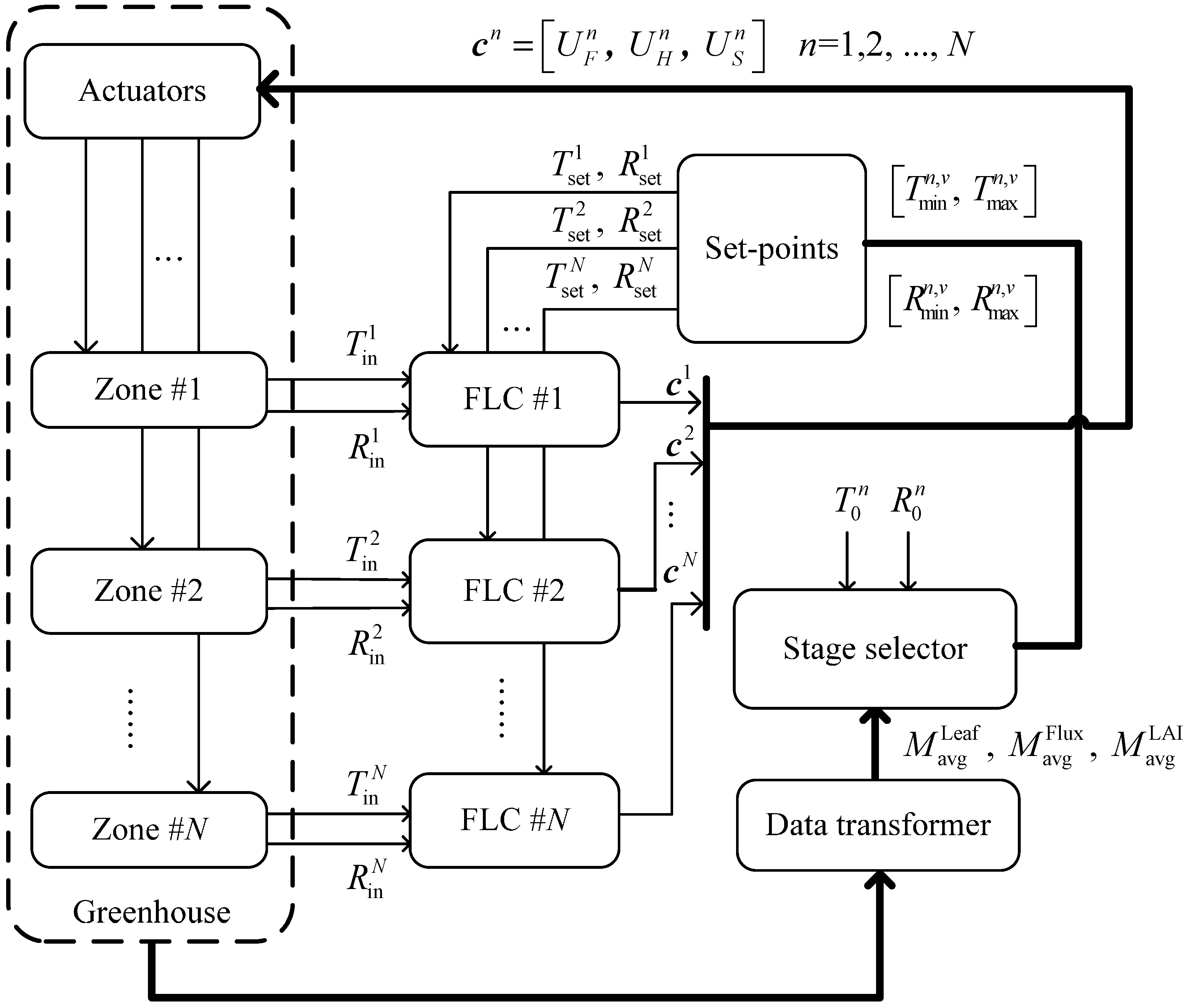
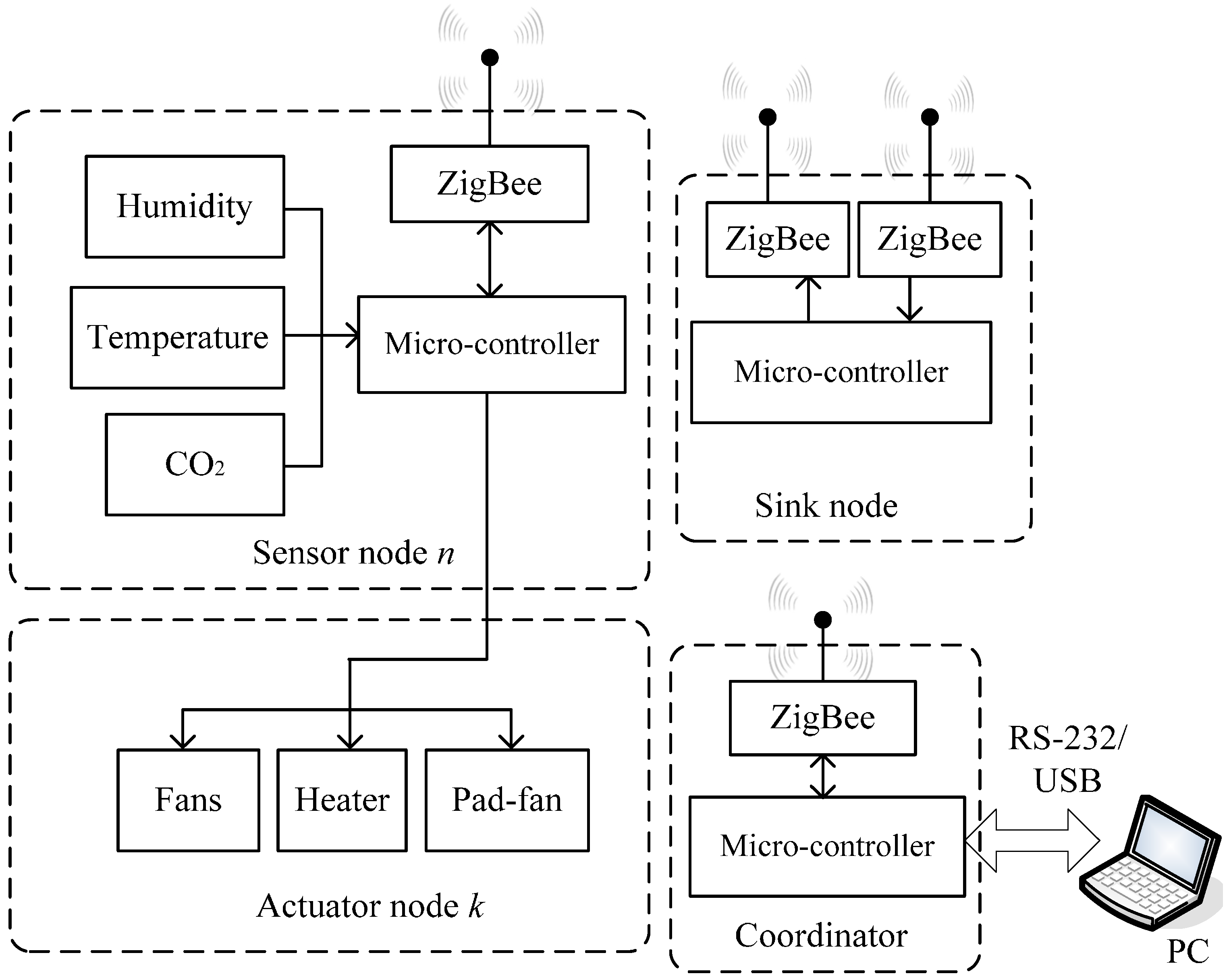
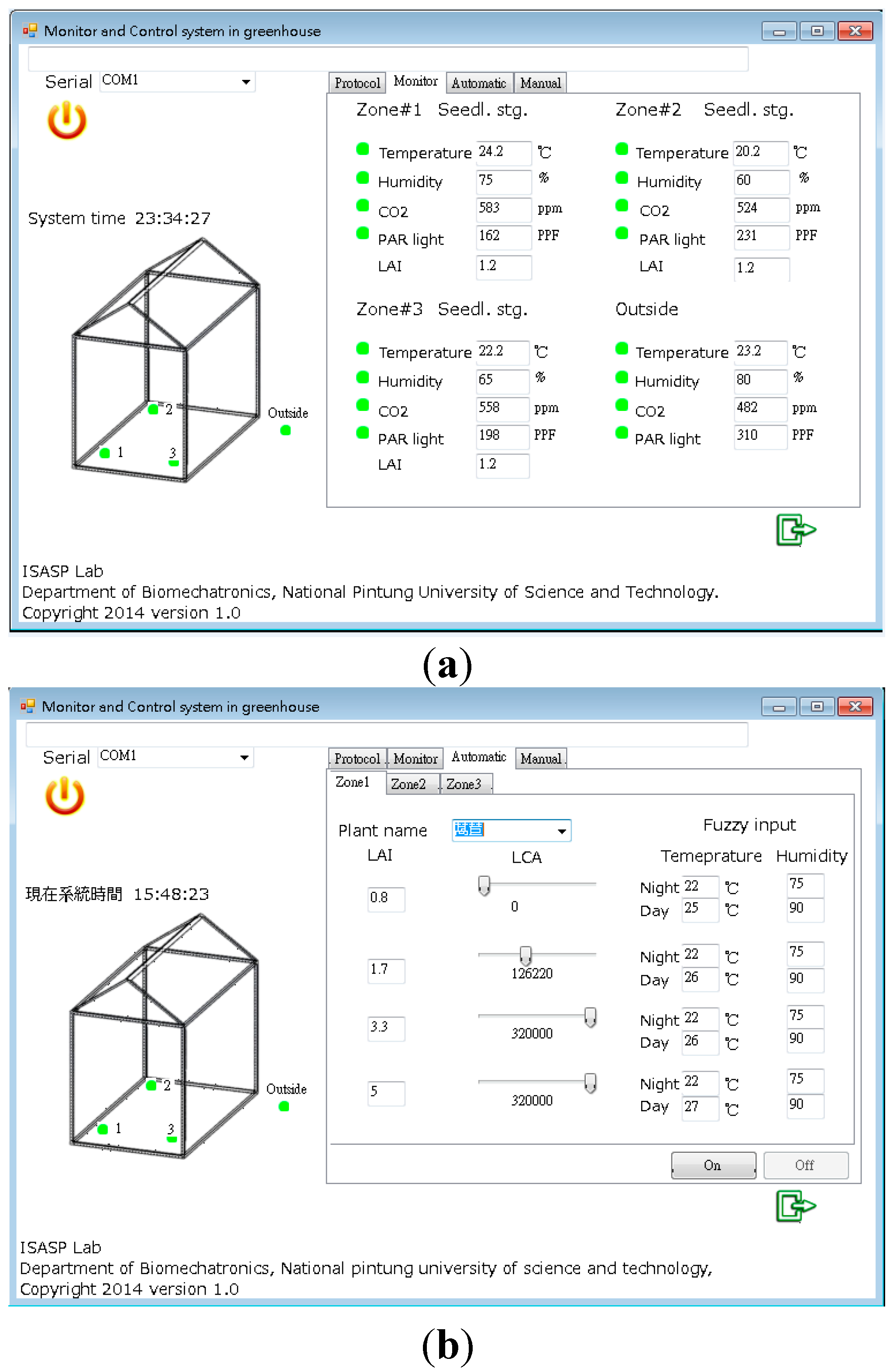
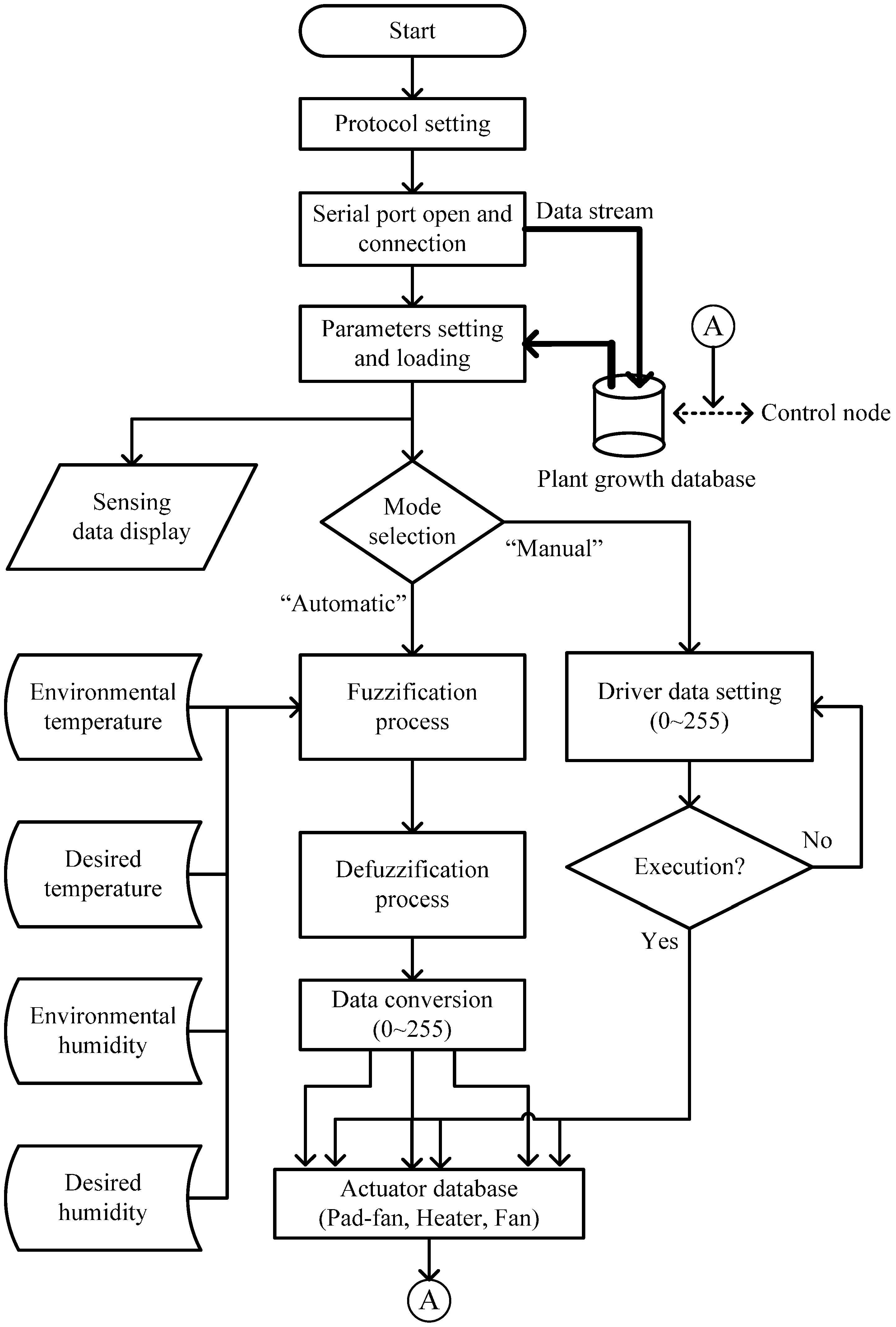
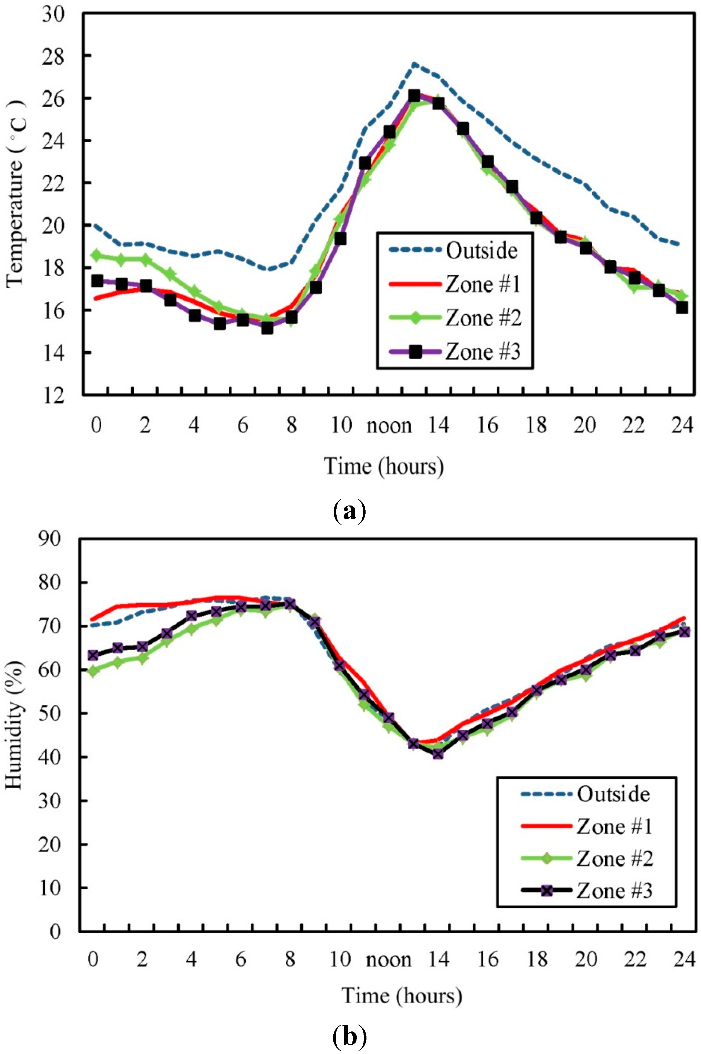
The proposed scheme consists of
fuzzy logic controllers (FLCs), a stage selector, a data a transformer, an actuator module, and a set-points module (see
Figure 2). The micro-environmental sensing data of various zones are sent to the fuzzy logic controllers, where fuzzy rule-based inference in the controller decides the starting conditions of the actuators in various zones and controls the actuator output. The
value of the plant growth stage is determined by the average leaf area index (
), the number of leaves (
), and the cumulative amount of light (
). When the
value is determined, the selector exports a temperature maximum (
), temperature minimum (
), humidity maximum (
), and humidity minimum (
) to the set-points module for No.
cultivation zone. The selector selects the target temperature and humidity within the range of temperature and humidity randomly. These data will be imported into the FLCs as the target temperature and humidity. The functions of each block are introduced, as follows.
Figure 2.
The block diagram of decentralized fuzzy control scheme.
2.2.1. FLC
Fuzzy logic inference technology is usually used to solve unknown or nonlinear control problems in a dynamic system. The core of the technology is to use the fuzzy rules created by expertise to control the system parameters. It is unnecessary to combine the mathematical model for environmental condition changes in the greenhouse with fuzzy controllers for temperature and humidity control. However, it is crucial to know the correlation between the input and output variables of the system, and to study the actuation degree of system output to equipment operation, such as the input voltage of heater (H), pad-fan (S) and the fan (F). The design process of fuzzy logic controller is shown as follows [
33]: (a) define the input and output variables; (b) define the membership type of fuzzification; (c) design control rules and fuzzy inference; (d) decision logic; (e) select the defuzzification method.
The first step is to fuzzify the input variables. The selection of input variable directly affects the manifestation of the controlled object, meaning it is necessary to consider the operational conditions that must be observed and measured. In each of fuzzy logic controllers, there are two input variables, which are temperature deviation
and humidity deviation
, defined as follows:
where
and
represent the target temperature and humidity set by controller
, where
and
represent current temperature and humidity, respectively. The fuzzy controller must make decisions according to the difference between the expected variable value and the actual variable value. It is noteworthy that there is mutual coupling correlation between temperature and humidity. Therefore, the temperature and humidity deviation are imported into the
and
factors, and the output equations are described by Equations (3) and (4):
where
and
values are 0~1. When
and
values are 0, the mutual coupling between temperature and humidity deviation is disregarded. When the
and
values are increased, the fluctuation of temperature and humidity deviation is reduced. Afterwards, the
and
need to be converted into a fuzzy linguistic (fuzzy set) for expression. By determining the number of fuzzy sets used based on the complexity of the control problem in terms of each input or output variable, each variable is matched with 3 different fuzzy sets in each fuzzy logic controller according to its category. Basically, a membership function is utilized to define how much of the temperature (or humidity) deviation “crisp” value is “small (S)”, how much is “moderate (M)”, and how much is “large (B)”. In addition, output variables of each controllers include normalized voltage of fan (
), voltage of heater (
), and voltage of pad-fan (
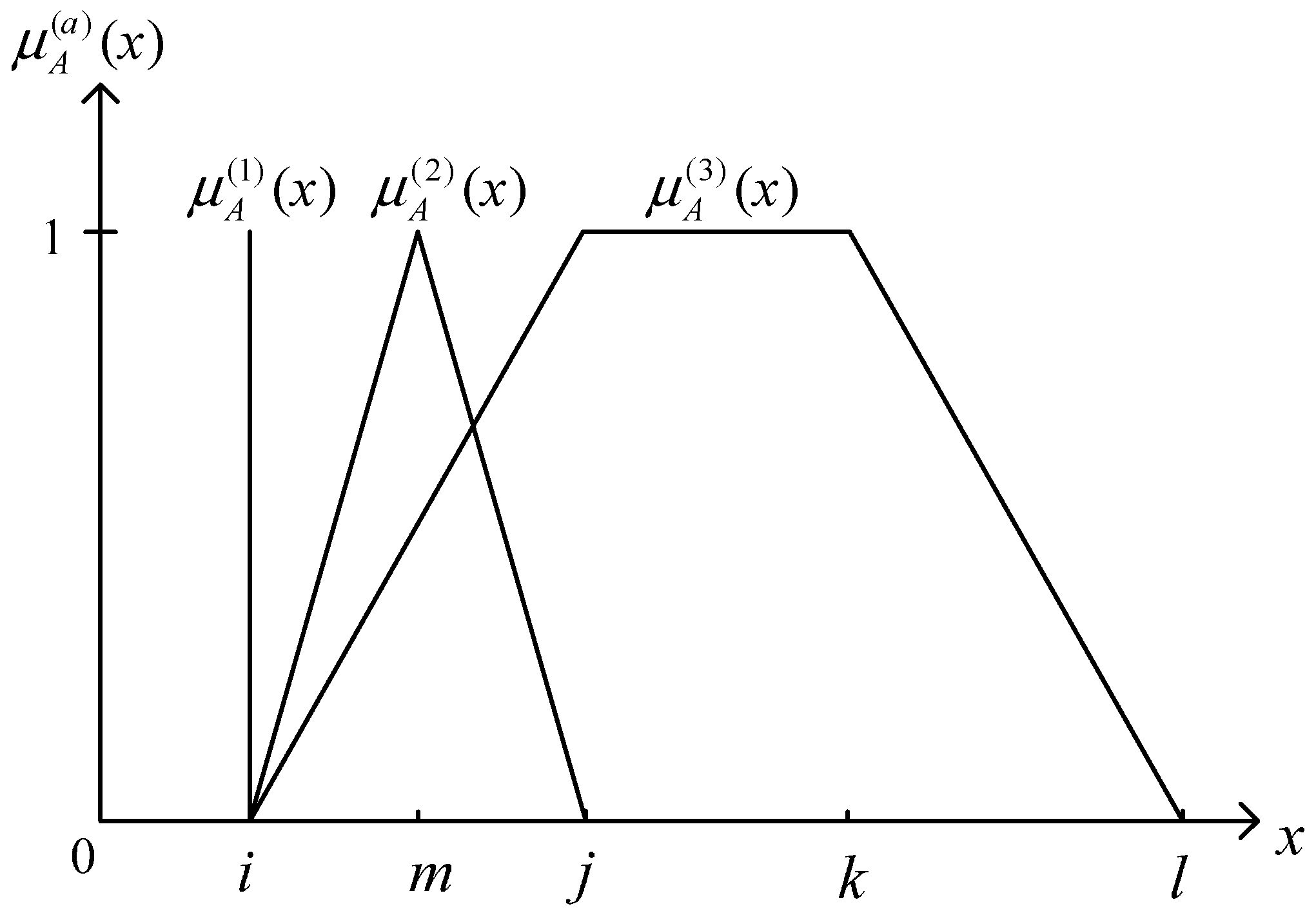
), whose fuzzy sets are low (L), moderate (M), and high (H), respectively. The membership function for fuzzy set
on the universe of discourse X is defined as
: X
[0,1], where each element of X is mapped to a value between 0 and 1. This value, called the degree of membership, quantifies the grade of membership of the element in X to fuzzy set
. The shape of the membership function will influence the degree value of each membership function corresponding to each input value, and directly influence the performance of the controller. The membership functions are defined as singleton membership function (
), triangle membership function (
), and trapezoid membership function (
), respectively, as these membership functions are simple. The different types of membership are shown in
Figure 3.
Figure 3.
Different types of membership functions.
Figure 3.
Different types of membership functions.
The mathematical equations are expressed as Equations (5)–(7).
Type I: Singleton membership function:
The points of the base can be depicted as .
Type II: Triangle membership function: defined by a lower limit
, an upper limit
, and a value
m, where
i <
m <
j.
The points of base can be demonstrated as [, , ].
Type III: Trapezoid membership function: defined by a lower limit
, an upper limit
, a lower support limit
, and an upper support limit
, where
i <
j <
k <
l.
The brackets [
,
,
,
] show the points of the base. The type and quantity of membership functions and the input variable range designed by each controller in this system are as listed in
Table 1.
Table 1.
Fuzzification parameter settings and different type of membership function determination.
Table 1.
Fuzzification parameter settings and different type of membership function determination.
| Variables | Fuzzy Subset (Linguistic Labels) | Type of Membership Function | Points of Base | Range |
|---|
| Temperature deviation () | | Trapezoid () | [−5, −5, −2.5, −0.5] | [−5, 5] |
| Triangle () | [−1.5, 0, 1.5] |
| Trapezoid () | [0.5, 2.5, 5, 5] |
| Humidity deviation () | | Trapezoid () | [−10, −10, −5, −3] | [−10, 10] |
| Triangle () | [−5, 0, 5] |
| Trapezoid () | [3, 5, 10, 10] |
| Fan () | | Singleton () | | [0, 1] |
| |
| |
| Heater () | | Singleton () | | [0, 1] |
| |
| |
| Pad-fan () | | Singleton () | | [0, 1] |
| |
| |
When the input variables are fuzzified, a group of fuzzy output values shall be obtained by the fuzzy inference process, and this inference process often uses an “If-Then” rule.
Table 2 describes the association rule base of input variables and output variables. For example, the fuzzy rule (1) statement in
Table 2 is:
Table 2.
Fuzzy rules.
| |
|---|
| S | M | B |
|---|
| S | | | |
| M | | | |
| B | | | |
After completion of the inference process, a decision is required. This group of fuzzy output values uses “min-max” synthesis inference for making decisions [
33]. During calculation, “
” is taken as intersection operator and “
” as the union operator. The maximum output membership value of the entire inference result is as shown in Equation (9):
where
,
, and
denote input variables;
depicts the output variable; and
is the total quantity of fired fuzzy rules.
is defined as Equations (5)–(7). Finally, a crisp output is obtained by defuzzification of the fuzzy output values after inference, where the fundamental purpose is to reduce the fuzzy membership grade to a single output value. The common methods include center of gravity, center of sum, and weighted average method. In this study, the weighted average method is taken for defuzzification (Mark II, 1994), as shown in the Equation (10).
where
is the fired rule quantity,
can be obtained through Equation (9), and
is the degree that the premise of rule
is satisfied.
is the normalized voltage, as a driver is adopted, and the scaling output value will range from 0 to 12 V; as the fuzzy membership function output by the system is singleton,
of Equation (10) can correspond to one weight value
. Therefore, Equation (10) can be rewritten as:
Finally, the fuzzy controller exports output data , where denote the crisp voltage output of the fan, heater, and pad-fan, respectively.
2.2.3. Growth Stage Selector
Many early environmental control methods use the ideal plant physiological model to determine the optimal environmental control value, which is then imported into the actual greenhouse system [
35]. This control mode is inflexible, and cannot dynamically adjust the environmental factor values in the greenhouse. Since 2004, dynamic regulation of environmental factors has received the attention of many scholars, and many methods have been proposed [
22,
36,
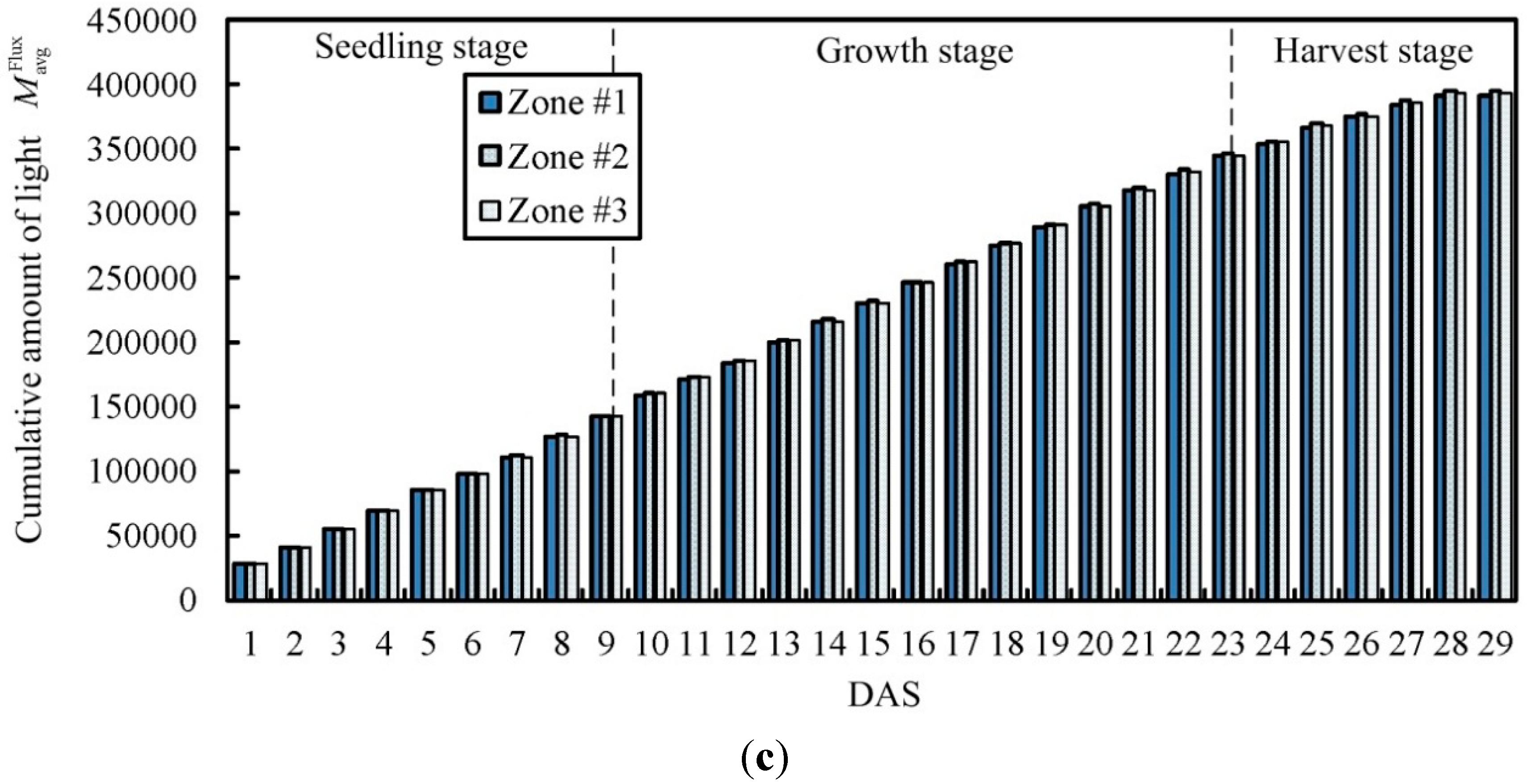
37]. In the proposed scheme, the output value obtained by each fuzzy controller in the system will be sent to the stage selector, which decides whether or not to start the actuators for various zones. The selector divides the plant growing process into three stages, which are the seedling stage, growth stage, and harvest stage. The required leaf area, number of leaves, and cumulative amount of light in each growth stage are as shown in
Table 3. The present stage of the plants is judged according to the plant growth leaf area average, number of leaves, and the required cumulative amount of light, so the three values must conform to the required conditions of the stage so that the growth stage of plants can be defined; otherwise, the previous growth stage will remain. In addition, if two output values are out of the set range, it is the “other” stage, and the previous growth stage remains.
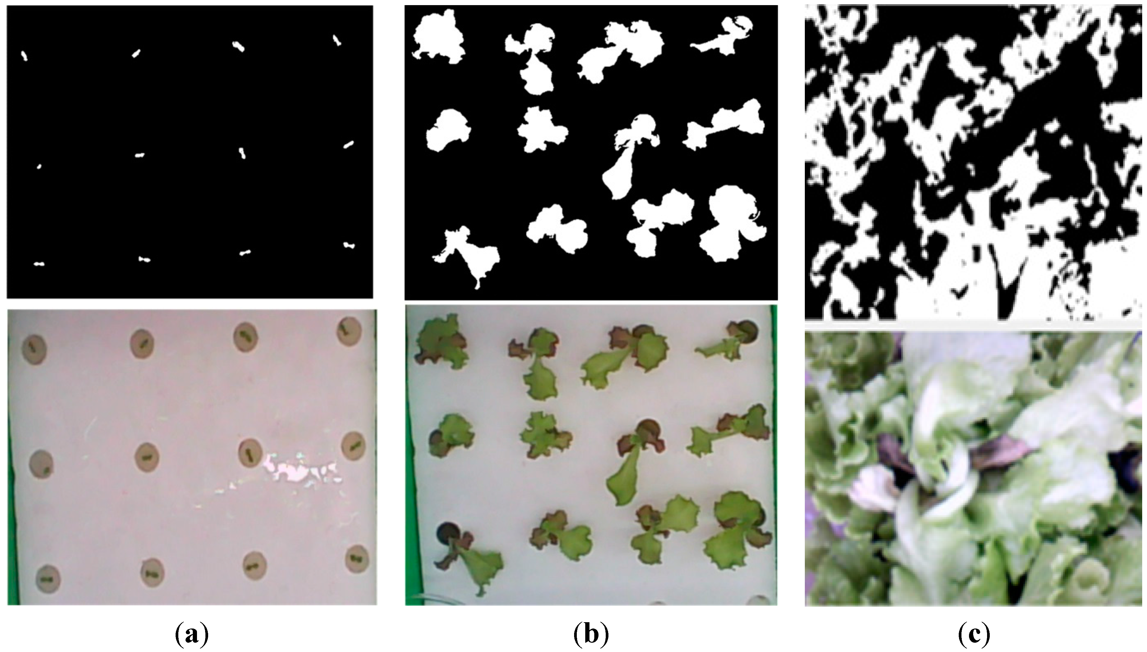
Table 3 takes lettuce as an example. The leaf area range of plant growth in each zone can be captured by the image device in the zone and calculated by binary conversion. In the same way, the number of leaves can be obtained from the image captured by image processing recognition. The lighting intensity can be obtained by the light quantum sensor in each zone. When the corresponding plant growth stage is found in
Table 3, the growth stage corresponds to the habitat temperature and humidity of the stage.
Table 3.
Plant growth stages corresponding to plant growth response intervals.
Table 3.
Plant growth stages corresponding to plant growth response intervals.
| Parameters | Leaf Area Index | Number of Leaves | Cumulative Amount of Light () |
|---|
| Growth Stage | |
|---|
| Seedling stage | | | |
| Growth stage | | | |
| Harvest stage | | | |
Table 4 shows the environmental conditions of temperature and humidity range corresponding to various growth stages, where
and
represent the preset temperature and humidity of the Zone #
n, respectively. The setup range in terms of temperature and humidity is based on the acquired parameters of previous cultivation experiments. These parameters are suitable for the current cultivation environment. When the cultivation site differs, the interior parameter still requires correction.
Table 4.
Target temperature and humidity range corresponding to various growth stages.
Table 4.
Target temperature and humidity range corresponding to various growth stages.
| Stage | Seedling Stage | Growth Stage | Harvest Stage |
|---|
| Range | |
|---|
| Temperature | | | |
| Humidity | | | |


