Low-Frequency Noise Evaluation on a Commercial Magnetoimpedance Sensor at Submillihertz Frequencies for Space Magnetic Field Detection


Abstract
:1. Introduction
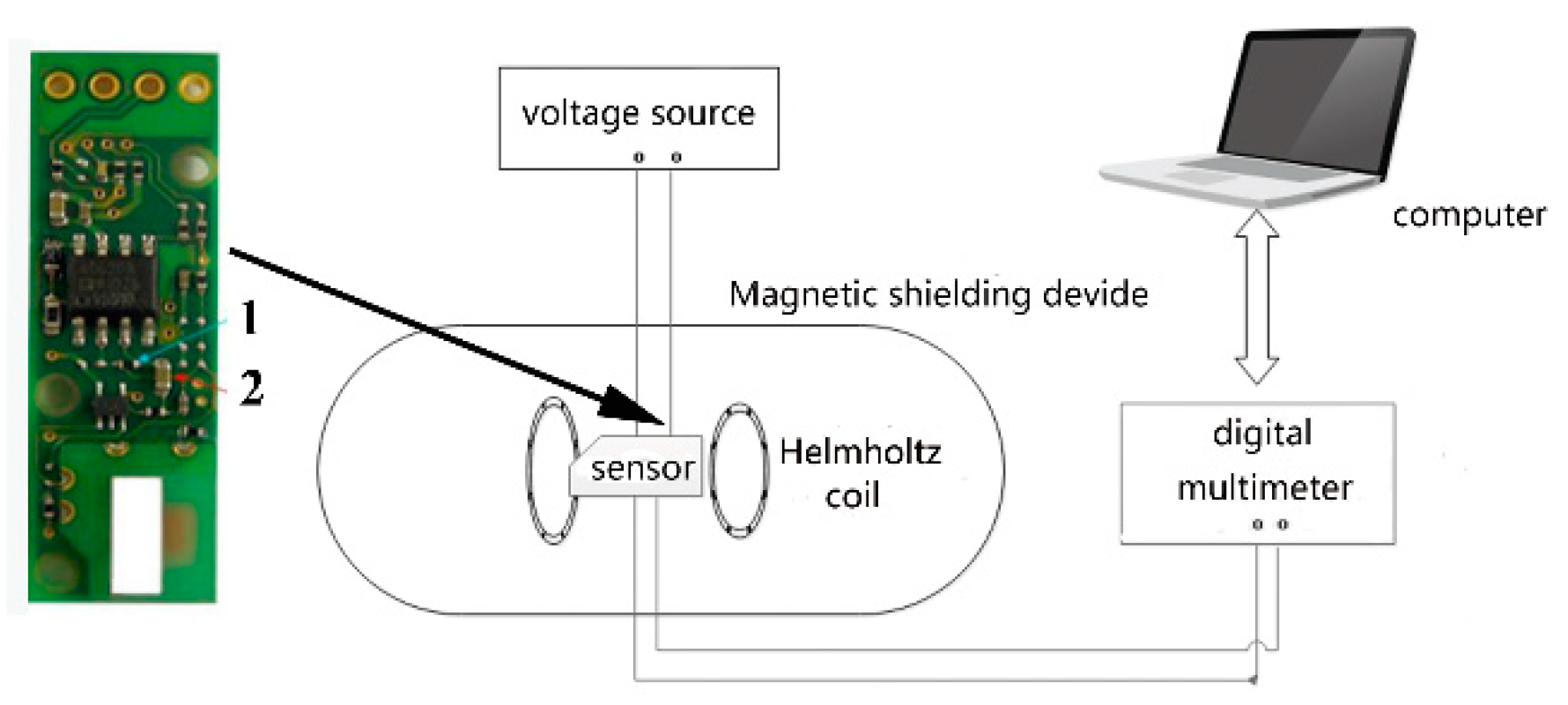
2. Measurement
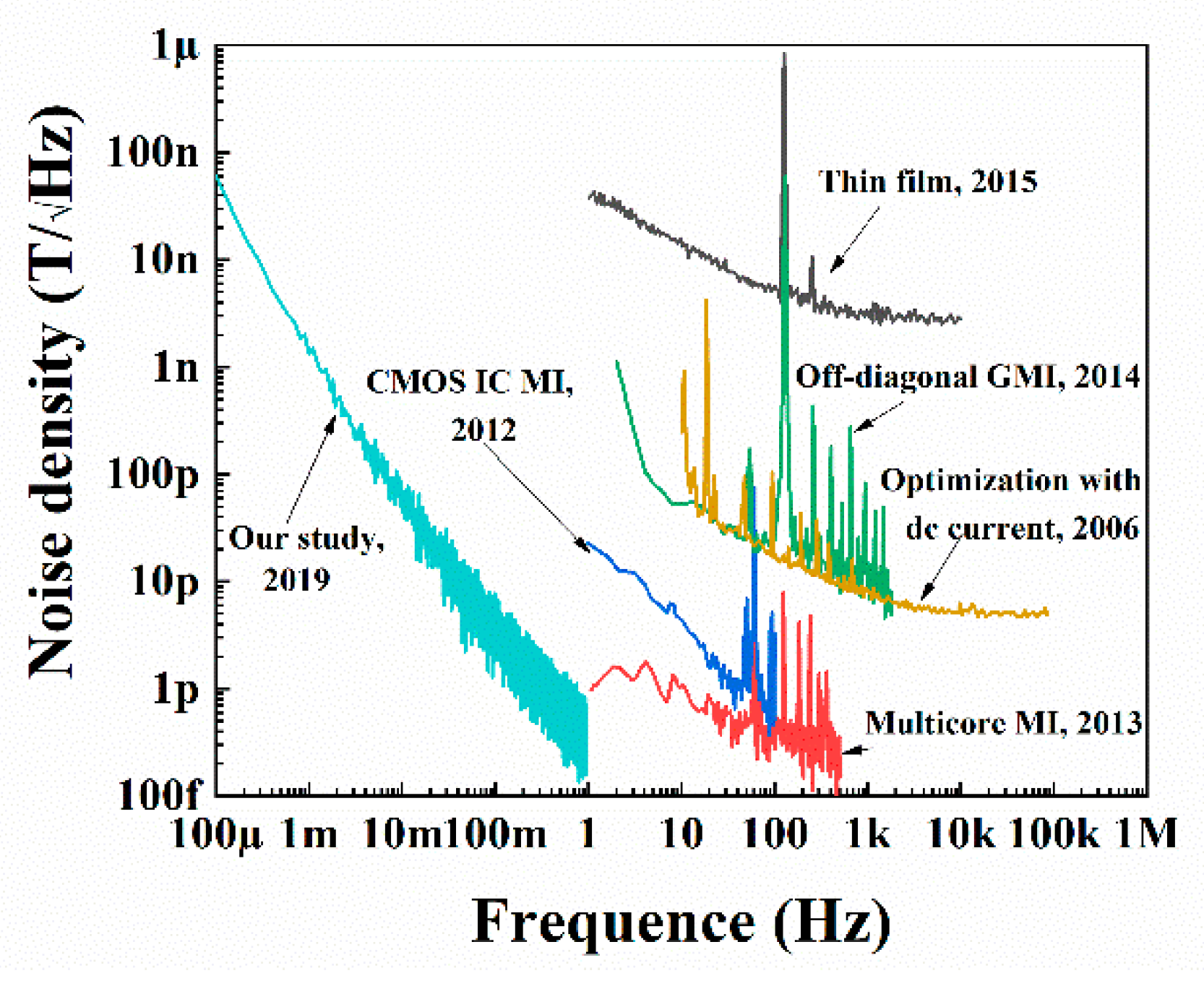
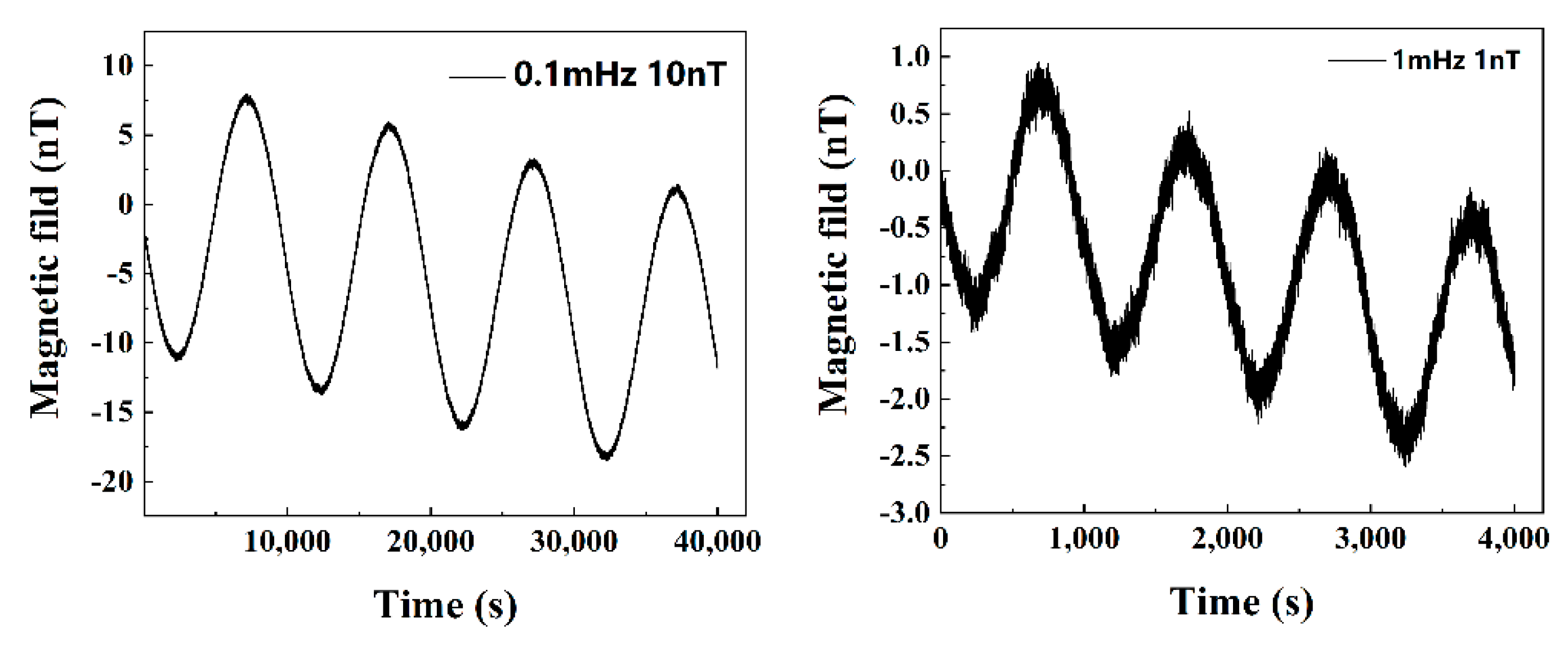
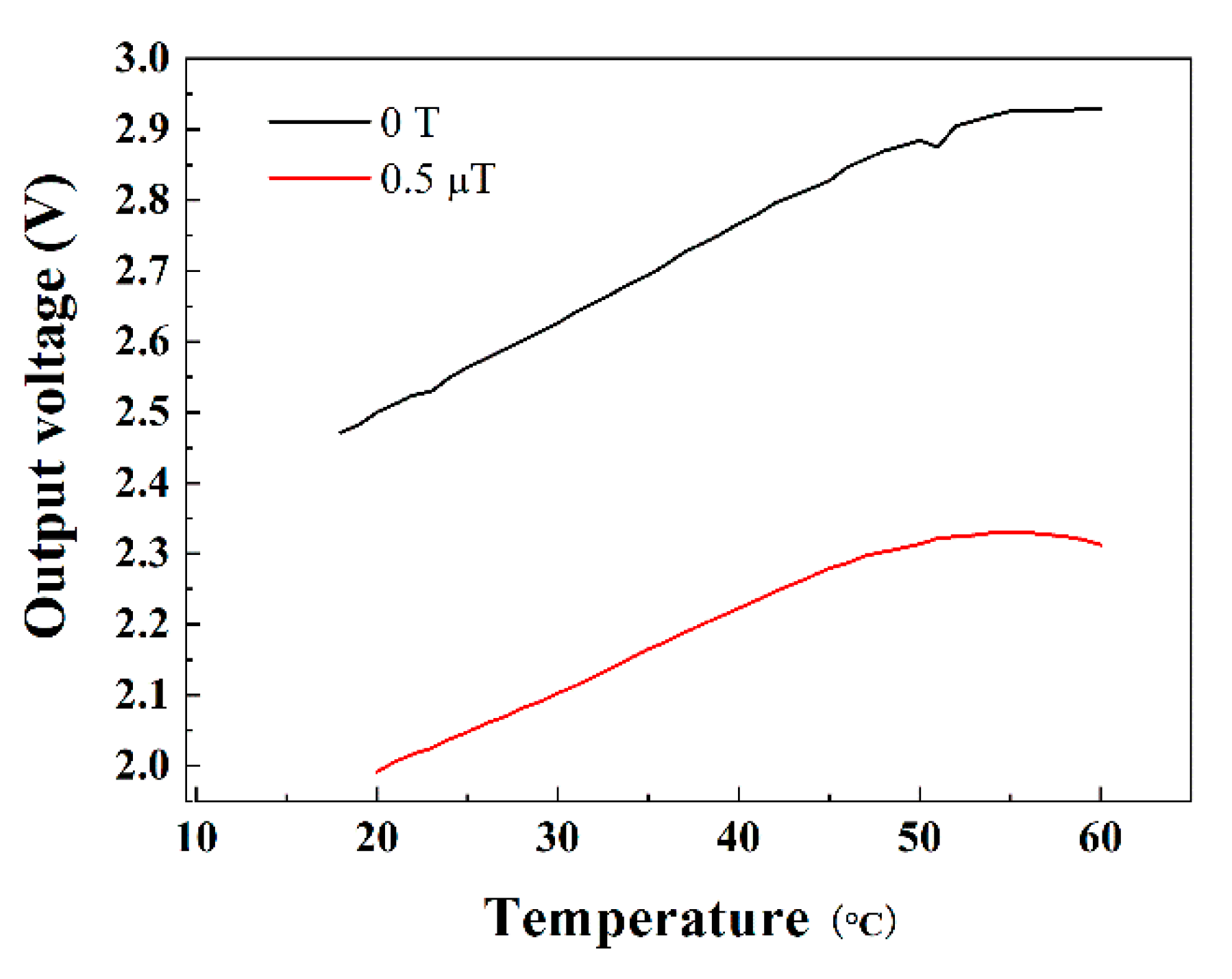
3. Results
4. Conclusions
Author Contributions
Funding
Acknowledgments
Conflicts of Interest
References
- Mohri, K.; Kohsawa, T.; Kawashima, K.; Yoshima, H.; Panina, L.V. Magneto-inductive effect (MI effect) in amorphous wires. IEEE Trans. Magn. 1992, 28, 3150–3152. [Google Scholar] [CrossRef]
- Bushida, K.; Mohri, K.; Uchiyama, T. Sensitive and quick response micro magnetic sensor using amorphous wire MI element in Colpitts oscillator. IEEE Trans. Magn. 1995, 31, 3134–3136. [Google Scholar] [CrossRef]
- Mohri, K.; Uchiyama, T.; Shen, L.P.; Cai, C.M.; Honkura, Y.; Aoyama, H. Amorphous wire and CMOS IC based sensitive micro-magnetic sensors utilizing magneto-impedance (MI) and stress-impedance (SI) effects and applications. In Proceedings of the 2001 International Symposium on Micromechatronics and Human Science, Nagoya, Japan, 9–12 September 2001. [Google Scholar]
- Alves, F.; Rached, L.A.; Moutoussamy, J.; Coillot, C. Trilayer GMI sensors based on fast stress-annealing of FeSiBCuNb ribbons. Sens. Actuators A. Phys. 2008, 142, 459–463. [Google Scholar] [CrossRef]
- Gudoshnikov, S.; Usov, N.; Nozdrin, A.; Ipatov, M.; Zhukov, A.; Zhukova, V. Highly sensitive magnetometer based on the off-diagonal GMI effect in Co-rich glass-coated microwire. Phys. Stat. Solidi 2014, 211, 980–985. [Google Scholar] [CrossRef]
- Chen, J.W.; Li, J.H.; Li, Y.Y.; Chen, Y.L.; Xu, L.X. Design and fabrication of a miniaturized GMI magnetic sensor based on amorphous wire by MEMS technology. Sensors 2018, 18, 732. [Google Scholar] [CrossRef] [PubMed]
- Uchiyama, T.; Mohri, K.; Honkura, Y.; Panina, L.V. Recent advances of pico-Tesla resolution Magneto-Impedance sensor based on amorphous wire CMOS IC MI sensor. IEEE Trans. Magn. 2012, 48, 3833–3839. [Google Scholar] [CrossRef]
- Panina, L.V.; Mohri, K. Magneto-impedance effect in amorphous wires. Appl. Phys. Lett. 1994, 65, 1189–1191. [Google Scholar] [CrossRef]
- Uchiyama, T.; Hamada, N.; Cai, C.M. Development of multicore magneto-impedance sensor for stable pico-Tesla resolution. In Proceedings of the 2013 Seventh International Conference on Sensing Technology, Wellington, New Zealand, 3–5 December 2013; pp. 573–576. [Google Scholar]
- Fernández, E.; García-Arribas, A.; Barandiarán, J.M.; Svalov, A.V.; Kurlyandskaya, C.V.; Dolabdjian, C.P. Equivalent magnetic noise of micro-patterned multilayer thin films based GMI micro sensor. IEEE Sens. J. 2015, 15, 6707–6714. [Google Scholar] [CrossRef]
- Mohri, K.; Uchiyama, T.; Panina, L.V.; Yamamoto, M.; Bushida, M. Recent advances of amorphous wire CMOS IC magneto-impedance sensors: Innovative high-performance micromagnetic sensor chip. J. Sens. 2015, 2015. [Google Scholar] [CrossRef]
- Billingsley Aerospace & Defense. Spaceflight Magnetometer Acceptance Router TFM100G4; Technical Report SN 114-118; Billingsley Aerospace & Defense: Germantown, MD, USA, 2007. [Google Scholar]
- Mateos, I.; Ramos-Castro, J.; Lobo, A. Low-frequency noise characterization of a magnetic field monitoring system using an anisotropic magnetoresistance. Sens. Actuators A. Phys. 2015, 235, 57–63. [Google Scholar] [CrossRef] [Green Version]
- Stutzke, N.A.; Russek, S.E.; Pappas, D.P. Low-frequency noise measurements on commercial magnetoresistive magnetic field sensors. J. Appl. Phys. 2005, 97, 10Q107. [Google Scholar] [CrossRef]
- Ding, L.H.; Saez, S.; Dolabdjian, C.; Melo, L.G.C.; Yelon, A.; Menard, D. Equivalent magnetic noise limit of low-cost GMI magnetometer. IEEE Sens. J. 2009, 9, 159–168. [Google Scholar] [CrossRef]
- M’enard, D.; Rudkowskaa, G.; Clime, L.; Ciureanu, P.; Yelon, A.; Saez, S.; Dolabdjian, C.; Robbes, D. Progress towards the optimization of the signal-to-noise ratio in giant magnetoimpedance sensors. Sens. Actuators A. Phys. 2006, 129, 6–9. [Google Scholar] [CrossRef]
- Vitale, S. Science Requirements and Top-Level Architecture Definition for the Lisa Technology Package (LTP) Onboard LISA Pathfinder (SMART-2); Technical Report LTPA-UTN-ScRD-Iss003-Rev1; University of Trento: Trento, Italy, 2005. [Google Scholar]
- Redmon, R.J.; Seaton, D.B.; Steenburgh, R.; He, J.; Rodriguez, J.V. September 2017’s geoeffective space weather and impacts to Caribbean radio communications during hurricane response. Space Weather 2018, 16, 1190–1201. [Google Scholar] [CrossRef]
- Seoane, P.A.; Aoudia, S.; Audley, H.; Auger, G.; Babak, S.; Baker, J.; Barausse, E.; Barke, S.; Bassan, M.; Beckmann, V.; et al. The Gravitational Universe. arXiv 2013, arXiv:1305.5720. [Google Scholar]
- Acuña, M.H. Space-based magnetometers. Rev. Sci. Instrum. 2002, 73, 3717–3736. [Google Scholar] [CrossRef]
- Diaz-Aguiló, M.; Mateos, I.; Ramos-Castro, J.; Lobo, A.; García-Berro, E. Design of the magnetic diagnostics unit onboard LISA Pathfinder. Aerosp. Sci. Technol. 2013, 26, 53–59. [Google Scholar] [CrossRef]
- Boukhenoufa, A.; Dolabdjian, C.P.; Robbes, D. High-sensitivity giant magneto-inductive magnetometer characterization implemented with a low-frequency magnetic noise-reduction technique. IEEE Sens. J. 2005, 5, 916–923. [Google Scholar] [CrossRef]
- Ding, L.; Saez, S.; Dolabdjian, C.; Ciureanu, P.; Melo, L.G.C.; Yelon, A.; Ménard, D. Intrinsic giant magnetoimpedance noise reduction by DC bias. Sens. Lett. 2007, 5, 176–179. [Google Scholar] [CrossRef]


| Parameters | Value |
|---|---|
| Linearity | 0.16% |
| Weight | 1.195 g |
| Size | 11 × 35 × 5 mm |
| Input voltage | 5 V |
| Input current | <20 mA |
| Power | <100 mW |
| Sensitivity | 1241 nT/V |
| Range | ±2 µT |
© 2019 by the authors. Licensee MDPI, Basel, Switzerland. This article is an open access article distributed under the terms and conditions of the Creative Commons Attribution (CC BY) license (http://creativecommons.org/licenses/by/4.0/).
Share and Cite
Wang, T.; Kang, C.; Chai, G. Low-Frequency Noise Evaluation on a Commercial Magnetoimpedance Sensor at Submillihertz Frequencies for Space Magnetic Field Detection. Sensors 2019, 19, 4888. https://doi.org/10.3390/s19224888
Wang T, Kang C, Chai G. Low-Frequency Noise Evaluation on a Commercial Magnetoimpedance Sensor at Submillihertz Frequencies for Space Magnetic Field Detection. Sensors. 2019; 19(22):4888. https://doi.org/10.3390/s19224888
Chicago/Turabian StyleWang, Tao, Chen Kang, and Guozhi Chai. 2019. "Low-Frequency Noise Evaluation on a Commercial Magnetoimpedance Sensor at Submillihertz Frequencies for Space Magnetic Field Detection" Sensors 19, no. 22: 4888. https://doi.org/10.3390/s19224888