1. Introduction
Magnetoelectric (ME) materials have the ability to convert energy between electrical and magnetic forms. Application of a magnetic field (H) results in a voltage output, or conversely an applied electric field (E) results in a magnetic flux change [
1,
2]. Consequently, ME materials have been investigated for potential applications as magnetic sensors, gyrator power converters, and field tunable communication devices. The ME effect was first found in Cr
2O
3 about 60 years ago, but the ME coupling effects in single-phase materials are very weak [
1,
2]. However, two-phase composites consisting of piezoelectric and magnetostrictive materials have been developed, which have very strong ME effects [
2]. Although the two phases individually do not have an ME effect, bonded together they have an ME product tensor property.
Our research team has previously developed ME heterostructures for passive (battery operated) magnetic sensors/receivers [
3,
4,
5,
6,
7]. Their operation used external magnetic fields to excite magnetostrictive layers into mechanical vibration. In turn, this mechanical vibration was transferred to the bonded piezoelectric layer, resulting in a voltage output. Wang et al. [
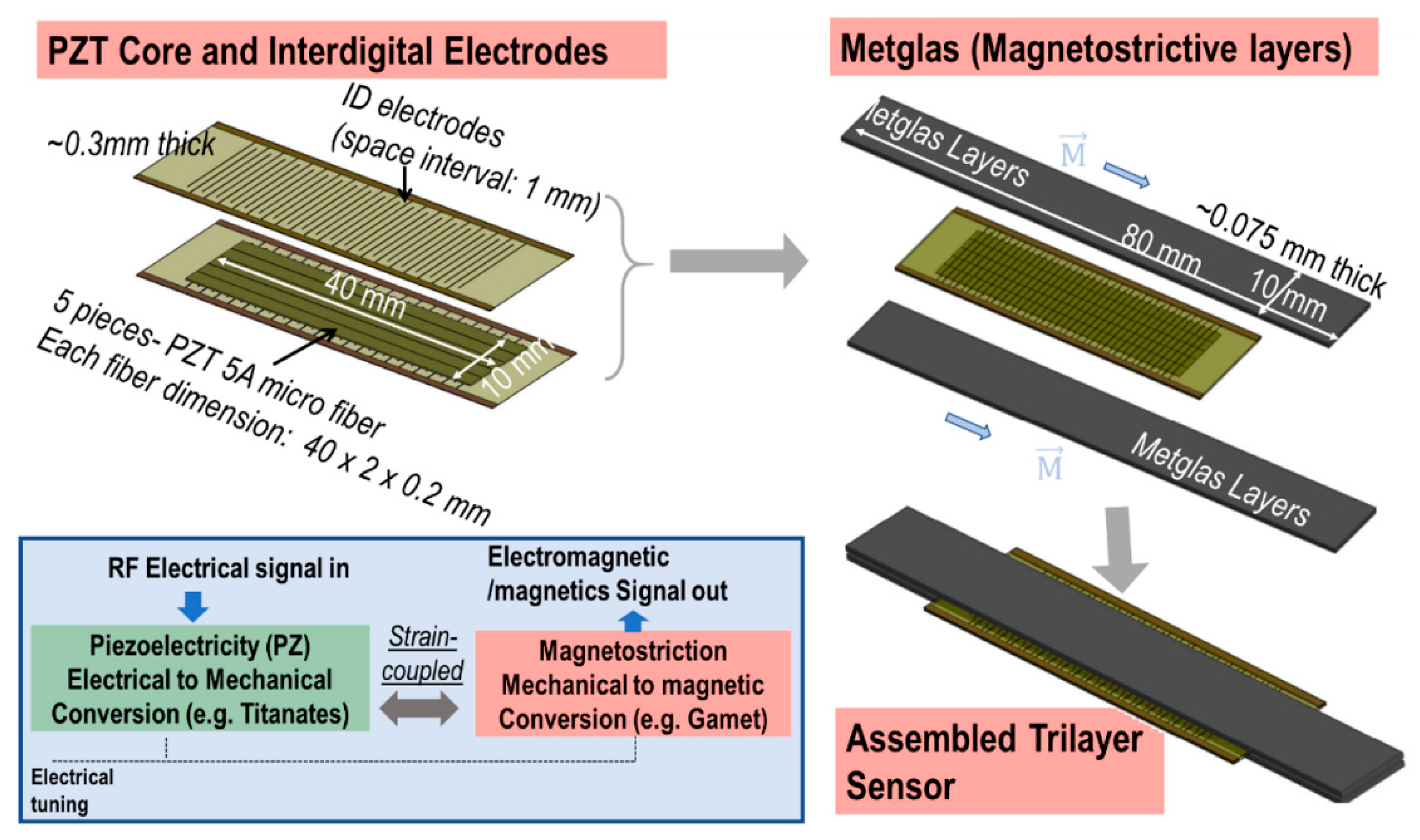
8] fabricated a longitudinal-longitudinal (LL) multi-push-pull structure using a piezoelectric layer bonded between two interdigitated electrodes (ID), and subsequently bonded to magnetostrictive layers forming a sandwich-like structure. A schematic of this ME sensor and its operation principal is depicted in
Figure 1. Magnetic sensors based on these laminates and a charge amplifier detection method have been shown to have an extremely low equivalent magnetic noise floor of 5.1 pT/√Hz at 1 Hz. A large ME voltage coefficient of 52 Vcm
−1Oe
−1 has been obtained under optimized direct current DC magnetic bias for Metglas/Pb(Mg
1/3Nb
2/3)O
3–PbTiO
3 (PMN-PT) trilayer laminates [
8,
9].
Furthermore, large gains in the ME properties of ME laminates have been reported near the electromechanical resonance (EMR) frequency. The highest resonance ME voltage coefficient reported is 1100 Vcm
−1Oe
−1, based on the structure shown in
Figure 1 [
8,
10,
11]. Later, even higher ME voltage coefficients have been achieved by optimizations of geometric configurations and improvements of interfacial bonding between piezoelectric and magnetostrictive phases. For example, Li et al. reported a spin-coat/vacuum-bag method, which could improve interfacial bonding and increase ME coupling [
12]. Furthermore, theoretical analysis has revealed that the resonance ME coupling coefficient in ME laminates can be significantly increased due to the improvement of the mechanical quality factor Q
m [
13]. Based on the discussions above, Chu et al. proposed a composite with (1-1) connectivity, which exhibited an enhanced resonance ME coupling coefficient of 7000 Vcm
−1Oe
−1 [
14]. This demonstrates the capabilities of ME sensors to have an excellent ability to receive low frequency (~30 kHz) and low power propagating signals, via utilizing this large ME gain effect at the EMR.
More recently, we have examined the transduction capabilities of ME heterostructures for power conversion devices and motors [
15,
16]. A highly efficient solid-state gyrator based on tri-layer composites consisting of two magnetostrictive ferrite layers epoxied to a Pb[Zr
(x)Ti
(1−x)]O
3 (PZT) piezoelectric core placed between the ferrite layers was developed [
17]. This electrical element used an input electric field to generate an output magnetic flux [
16,
18]. In turn, this flux induced current that flowed into an N-turns coil. Near the EMR, this ME gyrator exhibited a power conversion and transfer efficiency to a coil in the near field at about 90%, under low power density (0.61 mW/cm
3) and 75% under a higher one of 1.83 W/cm
3 [
19]. These results signify that ME laminates do not have significant radio frequency (RF)-losses at very low frequencies (VLFs), and thus have a potential for higher transmission efficiency. Accordingly, ME laminate offers the potential to design an ME based transmitter–receiver system, when operating near the EMR. Such resonance-based transmitter–receiver would also have a DC bias tunable frequency.
A VLF transmitter is located in Cutler, ME, USA that transmits 2 MW of power [
20]. It operates near 25 kHz and is capable of transmitting a signal around the world using a very small bandwidth at low data rates. The transmitter facility employs large towers spread across 2000 acres that has a radiation efficiency of 75% [
20]. Portable receivers for this VLF system are magnetic sensors that are widely available. The transmitters for VLF electromagnetic waves with portability are needed [
21]. Therefore, the reduction of the transmitter size needs to be investigated.
In this work, we are going to present the magnetic-field transmitting capabilities of the ME resonance sensors. The measurements of magnetic-field detection are presented, and we compared the proposed ME transmitter with a same-sized small current loop. Furthermore, the ME transmitter structure is also optimized to enhance the transmission.
4. Transmitted Magnetic Fields, Efficiency and Pattern Measurements
Next, we investigate the transmission and efficiency capabilities of the ME laminate (a 20M-trilayer) at the EMR. These measurements allow us to understand the possibility of the communication properties of the ME transmitter, but, beyond that, by comparing a known small loop antenna, the transmission efficiency can also be estimated. We use this approach in our investigation. Finally, the magnetic field patterns of the proposed ME transmitter are also presented.
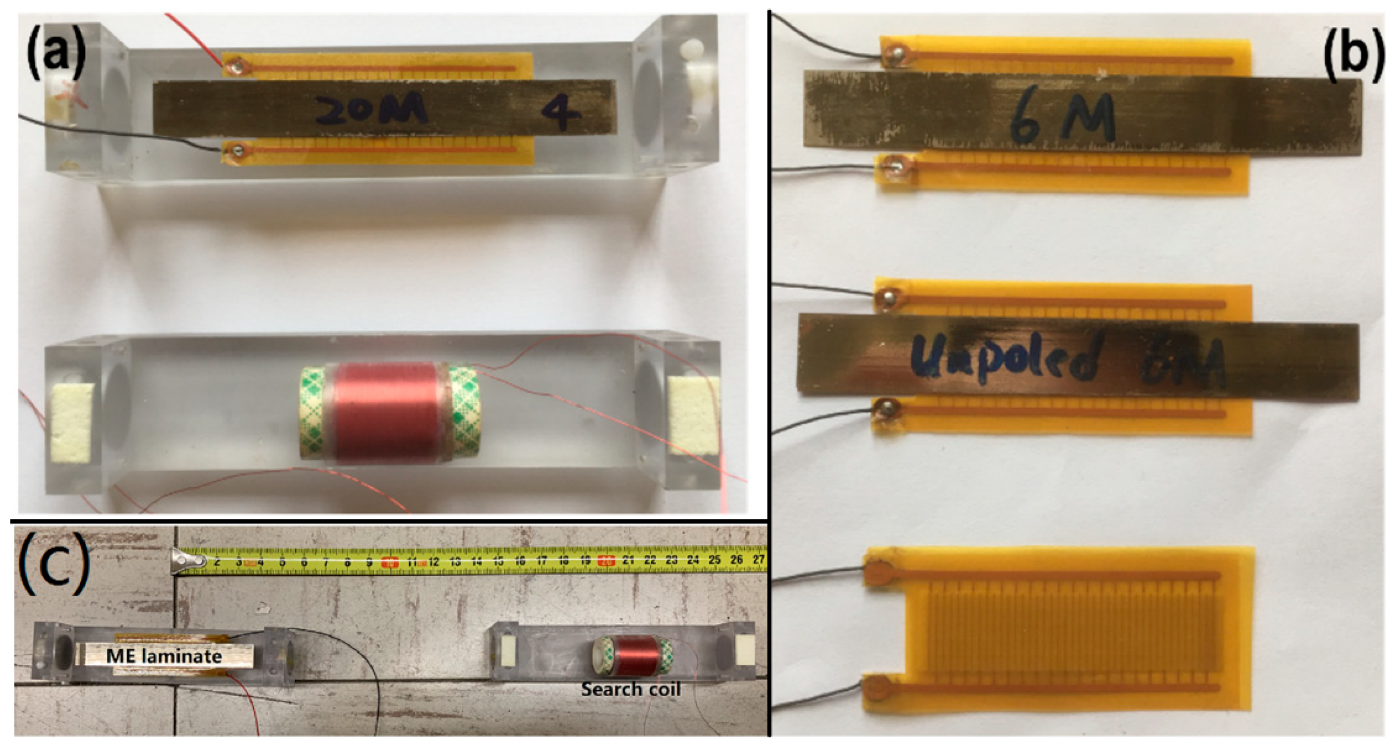
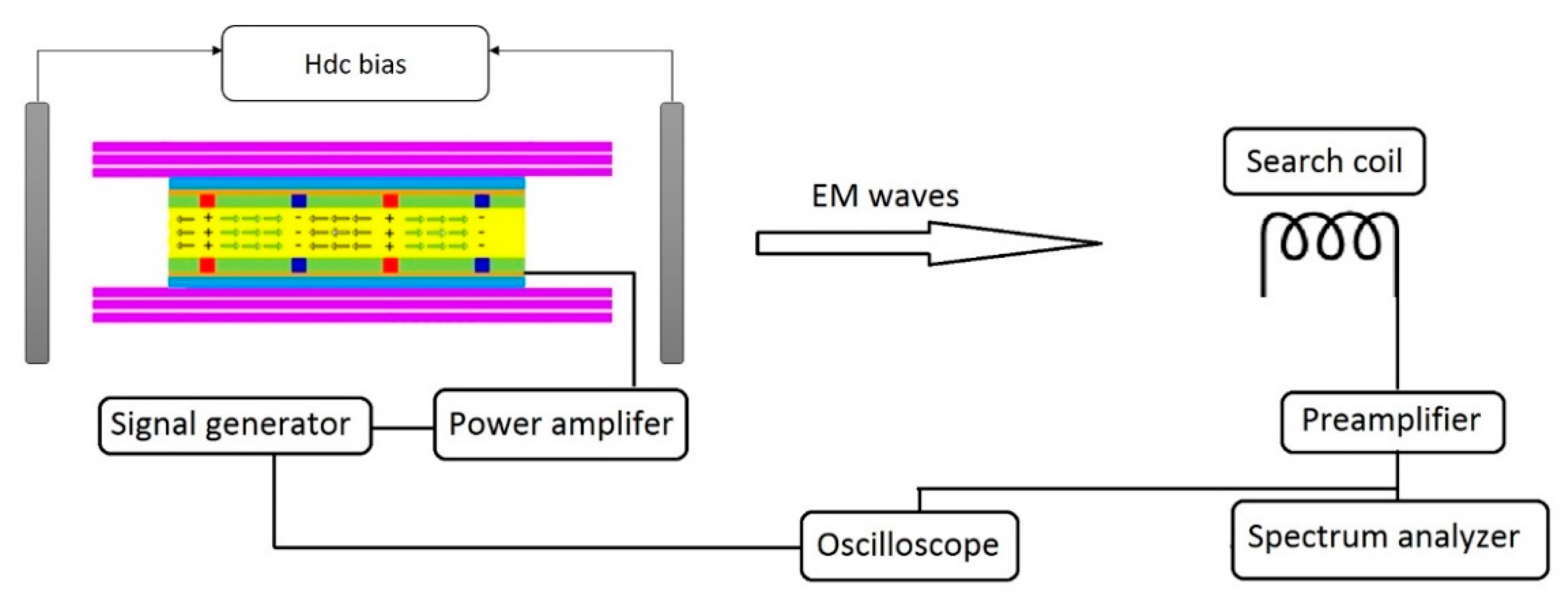
We use the set-up used in
Section 3.1 for characterization of the ME transmitter (20M trilayer structure). We apply an input power 100 mW to the ME laminate at resonance frequency f
r = 28.17 kHz. The distance between the ME transmitter and the receiver, r, was then sequentially increased from 0.4 m to 1.35 m.
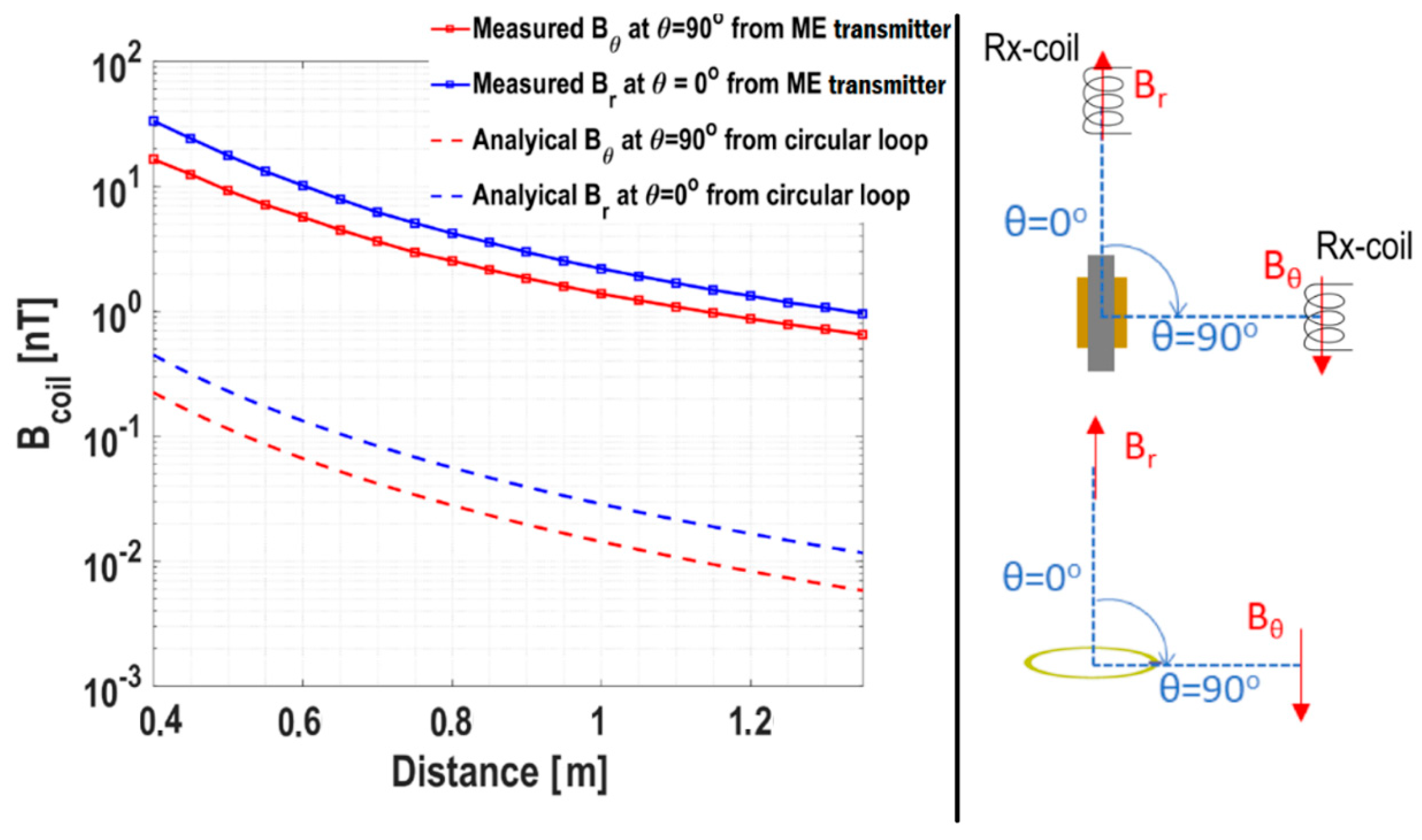
Figure 6 shows the flux density detected by the receiver as a function of r. We measured the flux varying with distance in two directions, i.e., θ = 0° and 90°. We measured the dominant flux components along each direction. Specifically, B
r (along θ = 0°) and B
θ (along θ = 90°) were measured. As shown, the magnetic-flux levels varied between 30 nT to 1 nT in the provided distance range. We will understand more about these values by comparing our results with a small current-loop antenna in the following subsection.
4.1. Comparison with a Small Current-Loop Antenna
To understand the transmission capabilities of the presented ME transmitter, it is apt to compare them with a canonical antenna structure. The size of the proposed current loop is as same as the ME transmitter, which is 16 cm
2. As is well known, a horizontal small circular loop is equivalent to a vertical magnetic small-dipole erected through the loop’s center. Given that and the fact that the ME transmitter has a magnetic-dipole like resonance along the longitudinal direction, this comparison is appropriate (
Figure 6, right).
First, using derivations provided in
Appendix A, the near field of the small loop of radius a can be derived as
and
Here, P
in is the input power applied at the port of the loop antenna, Z
o (= 50 Ω) is the impedance of the input transmission line, R
r ≈ 31,171
, with S = πa
2 is the radiation resistance of the antenna, η = 377 Ω is the free-space radiation impedance and permeability of the free-space is given by μ
o = 4π × 10
−7 H/m. k = 2π/λ is the propagation constant for a wavelength λ. To match the measurement conditions, P
in = 100 mW was chosen for the loop antenna. r is distance of the observation point from the center of the antenna and θ is the angle as shown in the right figure of
Figure 6. For a reasonable comparison, we chose the loop area to be S = 16 cm
2 (same as the area of ME transmitter 8 × 2 cm
2). Note that a factor of 1/√2 is added in B
r and B
θ to obtain root mean square (RMS) fields for the loop antenna for a rational comparison with the measurements. Measured B
coil is essentially RMS flux density as obtained from the oscilloscope voltage (refer to
Figure 3).
Figure 6 reveals a close match between the field-distance profiles from the loop antenna and the measured ME transmitter. Notably, according to Labels (2) and (3), ratio |B
r|/|B
θ| = 2 is expected. On average, this ratio was found to be ≈ 1.84 in the experiments. This is a reasonable agreement since we expect diffractions, reflection and refractions within the room, including that from the ground. Note that, because of low frequency and near-static fields (λ = 10 km), these interferences manifest themselves as constant additions of field, instead of inducing oscillations as generally expected in such distance profiles in the microwave regime. Furthermore, the empirical curve fitting suggests that the measured magnetic flux density decayed as 1/r
2.6. This is comparable with theoretical 1/r
3 given various sources of errors in the measurements. Finally, we also observe a difference in the field levels from a loop antenna and the ME transmitter. This is further discussed in the efficiency subsection next.
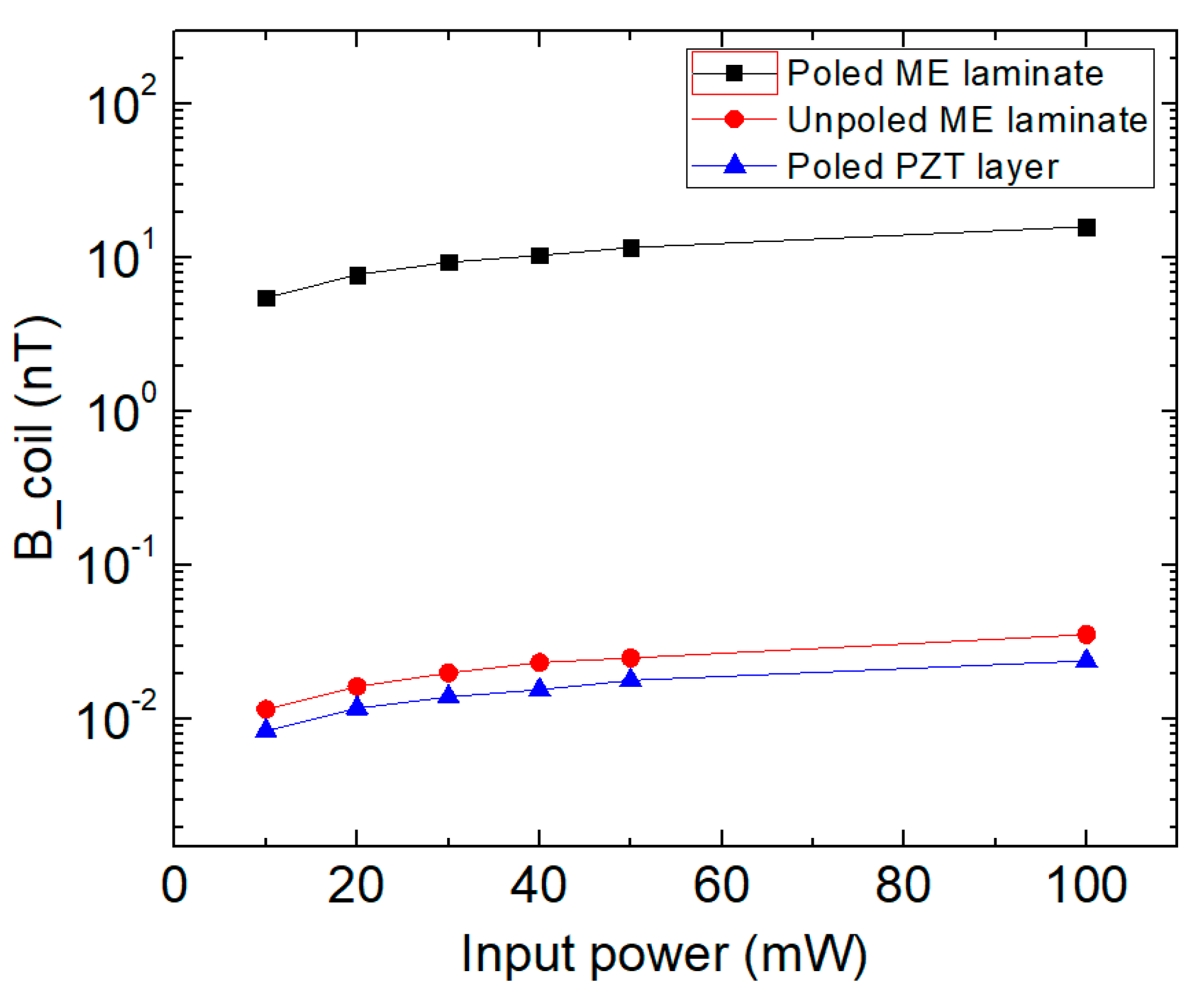
We also measured the magnetic flux density generated by the ME transmitter as a function of the distance with the highest power (500 mW) that we could apply. In
Figure 7, the black curve was measured with 100 mW, and the red one was measured with 500 mW. Extrapolating the 500 mW fitting curve, it can be estimated that a 1 fT flux could be detected around 200 meters. The background magnetic noise floor in an open environment at EMR (~30 kHz) is about a few hundred fT/√Hz [
24]. Therefore, a higher input power level or a greater number of transmitters could be added to increase transmitted magnetic fields.
4.2. Transmission Efficiency of the Magnetic Field
Efficiency calculations generally require knowledge of total transmitted power, which requires knowledge of 3D far-fields. However, this could be difficult for the kHz range antenna, due to large wavelength. Most modern antenna chambers support measurements only above a few tens of MHz.
Under these restrictions, we infer the transmission efficiency of the proposed ME transmitter by comparing its performance with the theoretical current-loop discussed above. We note that field ratio |Br|/|Bθ| = 1.84 confirms a similarity of ME transmitter with the loop antenna. Furthermore, we know that the ME transmitter at the EMR works like a magnetic dipole along the longitudinal direction due to the magnetic moment’s direction in the magnetostrictive layer. It is a reasonable assumption that the field-profile from ME transmitter and current-loop should match (as further confirmed in the pattern measurements in the next section) across the 3D space.
We also notice that the magnetic field produced by the loop is two orders smaller than the ME transmitter. For example, B
r at 90 cm from the ME transmitter is 2.9 nT and from the loop is 0.039 nT. This information, along with known radiation efficiency of the loop antenna, can be used to calculate the radiation efficiency of the proposed antenna. We know that the radiation efficiency is proportional to magnetuc flux squared. Thus, the efficiency ratio of ME antenna (η
ME) and circular loop (η
loop) will follow as
Thus, the radiation efficiency of the proposed ME transmitter is expected to be three to four orders higher than a loop antenna of same area. This confirms the superior operation of the proposed ME transmitter in near-field and far-field. The proposed transmitter is efficient especially for the cases when the packing area is small, since it can provide higher efficiency within the same size.
We note that the efficiency of the loop antenna is extremely low (η
loop = 1.2 × 10
−19) due to a ≪ λ restriction at kHz range [
25]. That is, since the antenna is non-resonant, its radiation resistance is negligible as compared to the impedances of the typical transmission line. This means that most power will simply reflect back from the antenna port. In other words, the factor 1-|S
11|
2 is negligible. This is a typical challenge for antennas that are operating at much longer wavelength than their size. Even with such severe impedance matching challenges, the proposed ME transmitter provides substantial improvements in the low frequency (~30 kHz) transmission, causing the radiation efficiencies to be estimated in the order of 10
−16, which is three orders larger than for the loop antenna of the same size.
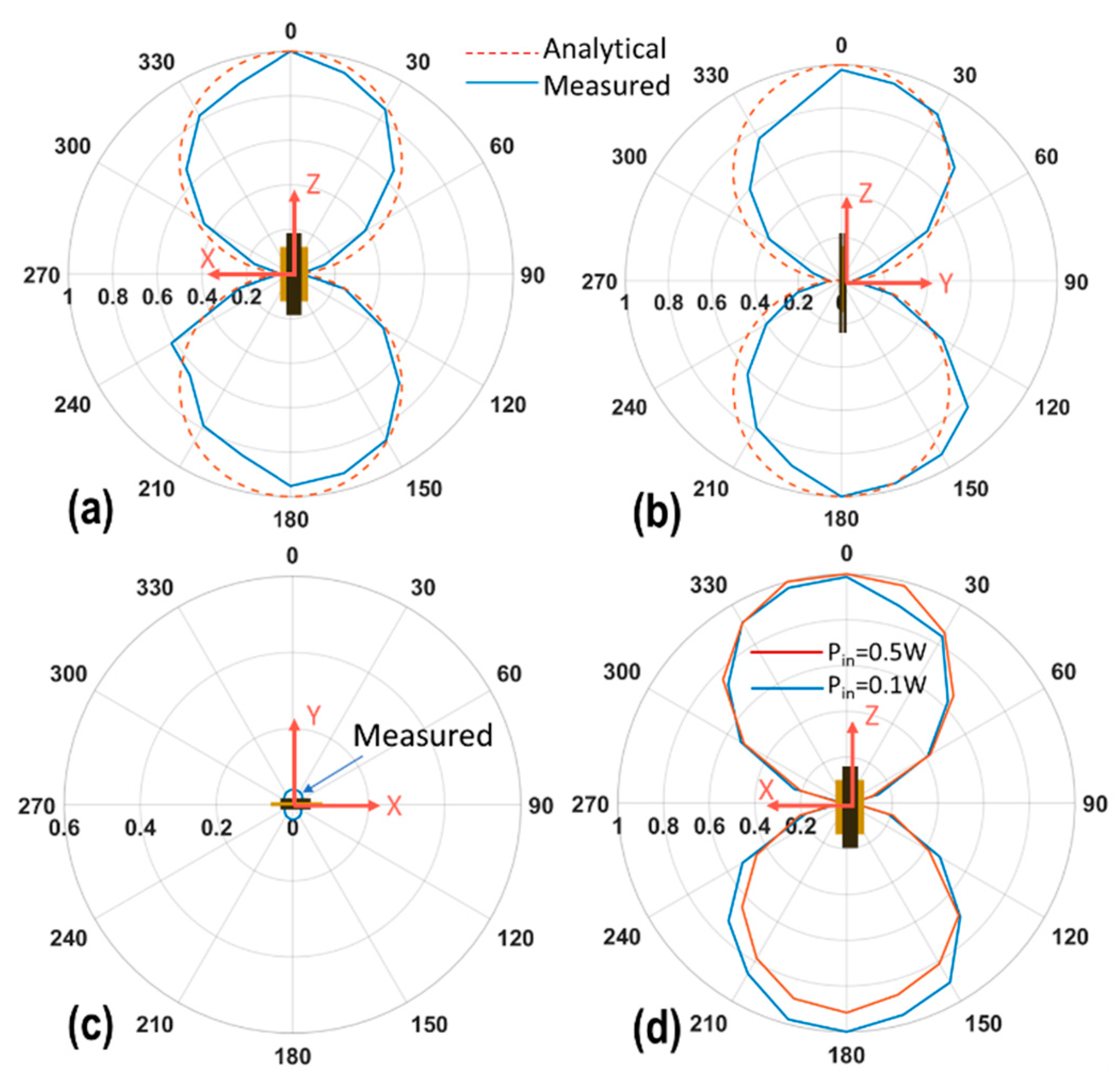
4.3. Pattern Measurements
To specify the orientation of the ME transmitter, we assume that the ME transmitter’s longitudinal direction along the
Z-axis, the width along the
X-axis, and the thickness along the
Y-axis. The magnetic field pattern measurements were done by sweeping the elevation angle θ in the XZ (or 001)-plane, YZ (or 010)-plane and XY (or 100)-plane. We chose to measure B
r component for these measurements by orienting the axis of the search coil towards the center of the sweeping circle. The radius of the circle was 0.5 m. The input power applied was 100 mW. The ME transmitter was working at its EMR for all the cases. The measurement set-up was similar to
Figure 3, but applied for varying θ.
The normalized magnetic field pattern profiles are shown in
Figure 8a–c, respectively. The maximum value of the magnetic flux density was measured in
Figure 8d of the red curve, which was 4.75 nT. The fields in XZ- and YZ-planes are normalized to their maximum value, as both fields were found to be in the tens on nT range. For the XY-plane, the fields are found to be one order smaller than XZ, YZ-planes. The normalization is conducted with a maximum of the XZ-plane to show the NULL along the XY-plane (
Figure 8c).
The B
r field component follows the cosine field profile for XZ-(001) and YZ-(010) planes, confirming a magnetic-dipole (or horizontal small-loop) like operation predicted by Label (2). We note that the detected field in the XY (100)-plane in
Figure 8c was one order smaller than
Figure 8a,b, which effectively represents a NULL at θ = 90° based on Label (2). However, the power in the (100) plane was still measurable, which is probably due to a slight asymmetry of the ME transmitter and receiver.
Additionally, comparison of the normalized magnetic-field patterns measured using a single ME laminate under input powers of 100 mW and 500 mW was made along the XZ-(001) plane. Both patterns are shown in
Figure 8d. Their overlap confirms the linear operation of the ME transmitter, i.e., the transmitted fields linearly increase with the applied input power. This is an important observation, given the nonlinear physics of the ME laminates in consideration.

 ,
, 