2.1. Structural Design of the Exoskeleton
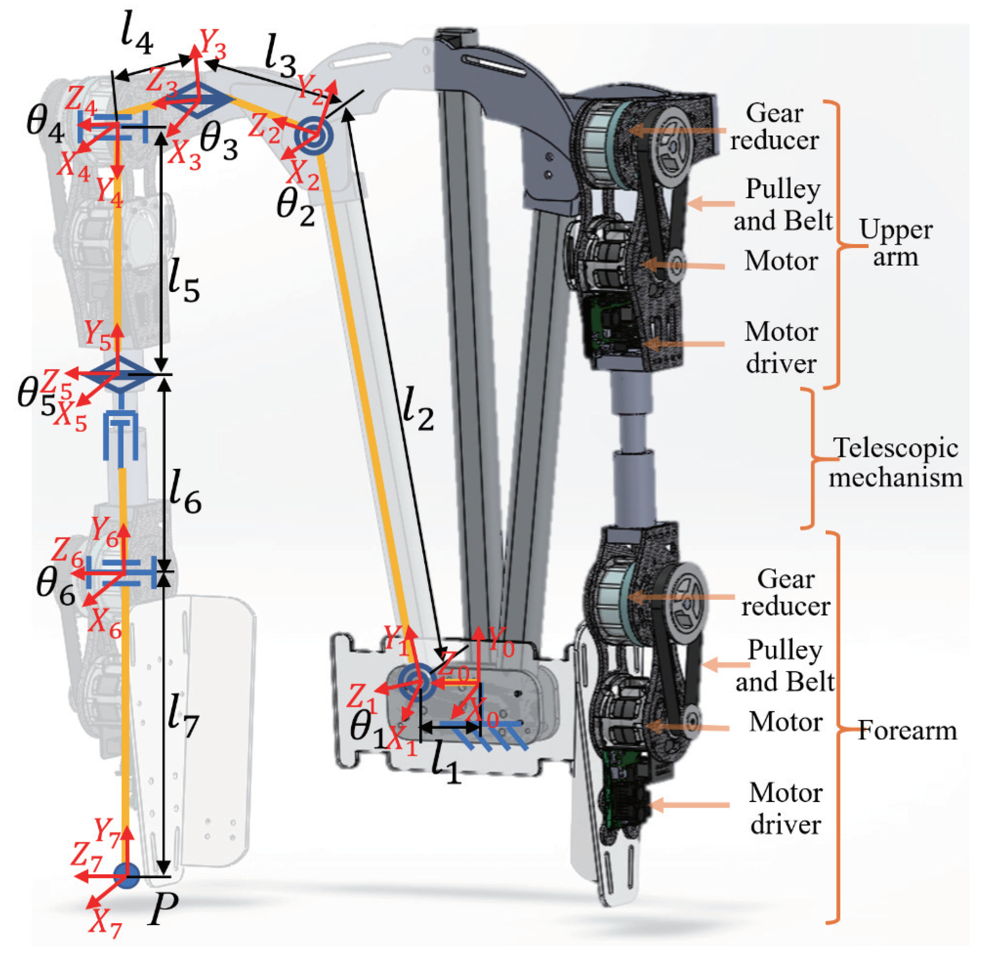
The exoskeleton was designed on the basis of the DOF of the human shoulder and elbow joints, and its overall design is shown in
Figure 1. A single arm of the exoskeleton consists of six rotary joints and a telescopic mechanism. The specific design parameters are listed in
Table 1. The combination of
,
, and
corresponds to the abduction/adduction of the shoulder,
corresponds to the flexion/extension of the shoulder,
corresponds to the internal/external angle of the shoulder, and
corresponds to the flexion/extension of the elbow. Finally,
and
correspond to the active joints, which can provide power assistance to the wearer. The others are passive joints, which can follow the wearer’s movements, and do not affect the wearer’s free movement. With the combination of active and passive joints, the exoskeleton could exhibit the necessary power-assist capability; thus, the number of motors was reduced, and the cost and weight were controlled. In the exoskeleton, the motors and reducers accounted for most of the weight. Carbon fiber materials were employed to fabricate the main structural parts to lower the weight; thereby, the weight of the two-arm prototype was reduced to 5.1 kg (excluding the weight of the batteries).
The exoskeleton could also be adapted to the shoulder width by the passive joint () and the upper-arm length (from shoulder joint to wrist joint) via the telescopic mechanism of for different wearers.
2.2. Design of Active Joints with Backdrivability
The exoskeleton (
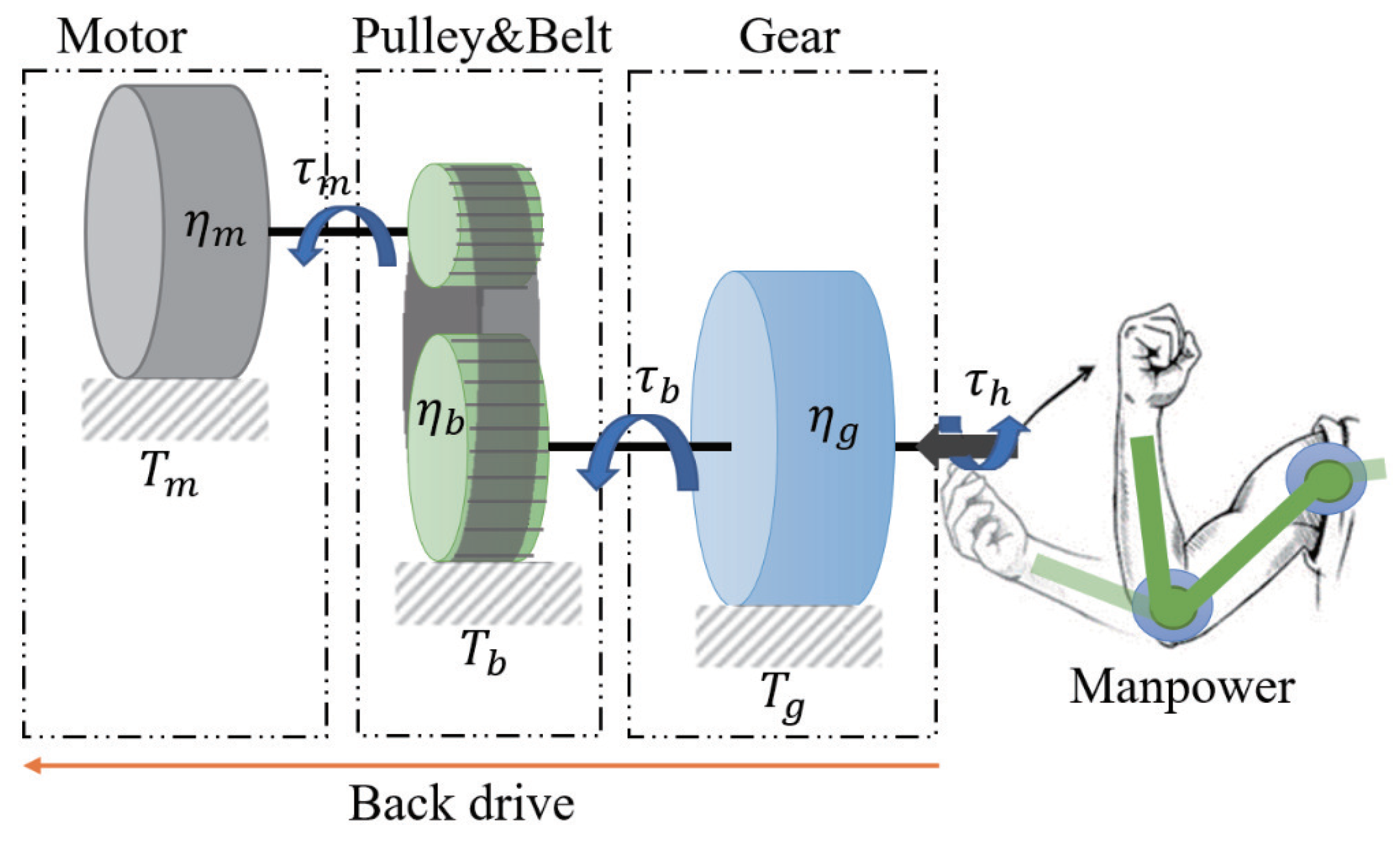
Figure 1) uses flat BLDC motors (EC45flat-70W, Maxon Motor Co., Sachseln, Switzerland) as the actuators, which deliver the output to the active joints of the exoskeleton after two-stage reduction. This setup consists of a timing-belt pulley set red (3:1) and a gear reducer (100:1). The corresponding schematic is shown in
Figure 2. This approach facilitated achievement of a high reduction ratio and simultaneously realized the parallel assembly of the motor and reducer through the transmission of the timing-belt pulley set; thus, the thickness of the active joints and the space occupied by the exoskeleton outside the wearer were effectively reduced. As a result, the exoskeleton can better fit the wearer’s body, improving comfort while it is worn, and it is easier to control, debug, and maintain.
Backdrivability is a critical criterion for wearable exoskeletons. It is a measure of how easily a torque applied on the output axis inversely drives the input axis and the motor [
25]. Therefore, for the exoskeleton to be driven backward, the wearer has to overcome the rotation resistance of the exoskeleton and drive the exoskeleton to move. In other words, large rotation resistance impairs the backdrivability.
During backdriving, the gear reducer and timing-belt pulley can increase the speed in the system. Their backdrive transmission efficiencies are
and
, and their reduction ratios are
and
, respectively. When the wearer applies a torque (
) to the output shaft of the active joint (the output shaft of the gear reducer), the torque is transmitted through the gear reducer, and a torque (
) is generated to drive the timing-belt pulley. This in turn generates a torque (
) to the motor shaft after it passes through the timing-belt pulley set. During backdrive, the torques
,
, and
on each rotating shaft overcome the friction torques
,
, and
of the gear reducer, timing-belt pulley, and motor, respectively, to perform backdrive. The required input torque
can be expressed as follows:
It can be observed from Equation (
1) that, in order to enhance the backdrivability via reduction in
, lowering the friction torque and reduction ratio and improving the backdrive efficiency are effective approaches. However, under normal circumstances, to ensure the output torque of the exoskeleton, a high reduction ratio is required. Therefore, the most direct and feasible approach is to improve the backdrive efficiency of the transmission system and reduce the friction torque.
In the current system, the friction torque of the motor and the timing-belt pulley set (
and
) are 4.9 mN·m and 1.0 mN·m, respectively. Despite the values being small, these parameters are amplified by the reducer when driven backward. Because of its high transmission efficiency (96.0%) and small friction torque, the timing-belt pulley set does not have a significant influence on the backdrivability when used for the first-stage reduction. However, the maximum reduction ratio the pulley can provide is limited by its diameter. Thus, it is critical to choose a suitable gear reducer for the second-stage reduction. In this study, a newly developed bilateral drive gear [
26] with high backdrivability was selected, and its reduction ratio is 100:1.
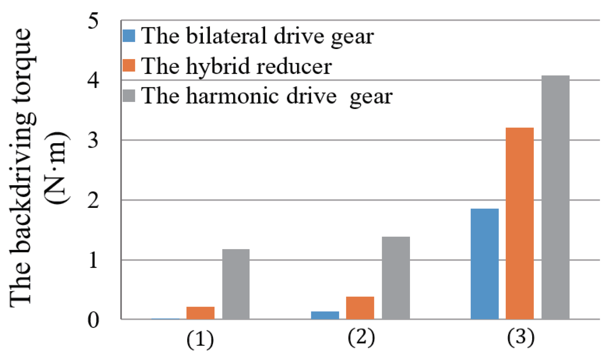
Herein, we compared the backdrivability of three different forms of gear reducers, namely, harmonic drive gears (CSF-17-100-2A-GR, Harmonic Drive Systems Inc., Tokyo, Japan), hybrid reducers (LGU75-4MLD/5MLG, Matex Co., Ltd., Osaka, Japan) and bilateral drive gears. They have similar shapes and the same reduction ratio. The harmonic drive gear is a gear reducer commonly used in robotic mechanisms. The hybrid reducer is a traditional planetary gear reducer. It has the advantage of combining any reduction ratio as needed.
The torque required to drive the following three groups of parts with the external torque was measured, respectively:
- (1)
The gear reducer only ().
- (2)
The gear reducer and the timing-belt pulley ().
- (3)
The gear reducer, timing-belt pulley, and motor, that is, the entire active joint ().
In measurements, a digital spring scale is hooked on the part connected output axis of the gear reducer and is pulled gradually until its force is big enough to make the axis start up rotation. This torque of starting up rotation is considered as the backdrive torque of the gear reducer that is the product of multiplying the force by the length from the axis to the hooking point of the digital spring scale. Similarly, three different types of gear reducers (bilateral drive gear, hybrid reducer and harmonic driver gear) are installed into the active joint of the exoskeleton in sequence, and their corresponding backdrive torque is measured, respectively.
The measurement results are shown in
Figure 3. The harmonic drive gear has the advantage of no backlash; however, owing to its elastic deformation characteristic, the torque required for the backdrive was as high as 1.17 N·m, and the backdrive efficiency was 54.6%. This largely reduced its backdrivability. For the hybrid reducer, a reduction ratio of 100:1 was adopted by combining three independent planetary gears (4:1, 5:1, 5:1). Although the torque required for backdrive was only 0.21 N·m, the connection transmission of multiple independent planetary gears affected the efficiency, and the backdrive efficiency was 67.4%, which also notably lowered the overall backdrivability. Finally, it can be observed that the bilateral drive gear exhibited clear advantages during backdrive. The starting torque required for backdrive was only 0.02 N·m, and the forward drive and backdrive efficiencies were 89.0% and 85.3%, respectively. The high efficiency and minimal friction torque during backdrive laid the foundation for reducing the starting torque of the active joint to 1.85 N·m when it was driven backward.
The active joint of the exoskeleton was designed in a two-stage reduction form, which effectively controlled the thickness of the active joint and ensured the high backdrivability while achieving a high reduction ratio (300:1). Thus, the wearer can easily drive the exoskeleton to move when it is not under control. Furthermore, the active joint renders the exoskeleton more convenient to wear and take off, which greatly improves the comfort and safety provided to the wearer.


