Abstract
Bismuth ferrite nanoparticles with an average particle diameter of 45 nm and spatial symmetry R3c were obtained by combustion of organic nitrate precursors. BiFeO3-silicone nanocomposites with various concentrations of nanoparticles were obtained by mixing with a solution of M10 silicone. Models of piezoelectric generators were made by applying nanocomposites on a glass substrate and using aluminum foil as contacts. The thickness of the layers was about 230 μm. There was a proportional relationship between the different concentrations of nanoparticles and the detected potential. The output voltages were 0.028, 0.055, and 0.17 V with mass loads of 10, 30, and 50 mass%, respectively.
1. Introduction
Piezo nanogenerators (PNGs) are promising sources of electricity that can power small electronics. Piezoelectric materials consist of both inorganic and organic components [1]. Since inorganic piezoelectric materials have better piezoelectric properties, they are the most widely studied. In turn, inorganic piezoelectric materials are classified into piezo crystals and piezo ceramics [2,3]. Research has mostly focused on piezoelectric materials, such as piezoelectric zinc oxide (ZnO) crystals [4,5,6,7,8] and piezoelectric lead zirconate-titanate (PZT) ceramics [9,10,11]. The good piezoelectric characteristics of ZnO in the form of nanowires are a consequence of its unique noncentrosymmetric structure. The method of obtaining them by growing on a substrate, however, is a long procedure that requires expensive equipment. In addition, it was reported that ZnO nanowires are characterized by a number of fundamental limitations associated with their semiconducting nature, for example, high leakage currents. They shield the piezoelectric potential formed in the material and require a Schottky barrier or p-n junction to achieve good energy-harvesting characteristics [4,12,13]. PZT is a widely used ceramic piezoelectric and has a high piezoelectric coefficient, excellent dielectric properties, [11,14,15] and ideal parameters for converting mechanical energy into electricity. However, due to the increased fragility of the thin film, PZT is not applicable for flexible and stretchable systems. The maximum safe mechanical stress for PZT is 0.2%, which indicates structural deformation even at low tension [16]. At the same time, one should not forget about the high toxicity of lead compounds.
As a result, the issue of creating a nontoxic piezoelectric material with high plasticity and low leakage currents remains relevant. One of the potential candidates for widespread use is lead-free perovskite bismuth ferrite (BiFeO3). Practical interest in this material has manifested due to its simultaneous ferroelectric and antiferromagnetic states, with extremely high ordering temperatures (Curie temperature TC = 830 °C and Néel temperature TN = 370 °C) [17]. The presence of ferroelectric ordering leads to the appearance of spontaneous polarization. From the empirical relationship PS = (258 ± 9) Δz μC/cm2, established by Abrahams et al. [18], it is assumed that for bulk BiFeO3 the PS values can be 98–108 μC/cm2. In practice, however, significantly lower values were observed. Although such values were not achieved for bulk ceramic materials, it was theoretically predicted that the ferroelectric properties of nanosized BiFeO3 would increase with decreasing particle size [19]. At the same time, measurements on thin films of high quality [20], single crystals [21] and ceramic polycrystals [22] showed that PS is about 60–100 μC/cm2 along the polar axis, which is consistent with Abrahams et al. This difference in PS values is explained by the presence of secondary phases, defects, volatilization of bismuth atoms at high temperatures, and electron hopping between Fe ions, which lead to high values of leakage currents [23]. Thus, for practical applications, it is of interest to synthesize phase-pure and nanosized BiFeO3 with particle sizes less than 62 nm.
In this work, a promising composite material based on BiFeO3 nanoparticles was obtained; the PNG model was assembled on this basis, and the electrical properties of the device were investigated.
2. Experimental Technique
2.1. Synthesis
The BiFeO3 nanoparticles were synthesized by solution combustion. The synthesis process is as follows. The starting reagents Bi(NO3)3∙5H2O and Fe(NO3)3∙9H2O (molar ratio of Bi3+ and Fe3+ 1:1, with purity > 98) were dissolved in distilled water. Glycine (C2H5NO2, purity > 98) was added to the mixture on the basis of calculations regarding the concept of fuel chemistry [24]. The synthesis process consists of three main steps: formation of a combustion mixture, formation of a gel, and then combustion of a gel. The solution was heated at ~300 °C for 1.5 h until dehydration and was stirred with a magnetic stirrer for homogenization. As a result, the formed gel ignited spontaneously with the release of gases and the formation of a powder. The synthesized powder was calcined at a temperature of 600 °C (Furnance: Nabertherm LF-15/14) in air. The desired temperature was reached at a rate of 5 °C per minute and held for 30 min. Details of the synthesis technology are presented in our previous work [25].
2.2. Preparation and Measurement Technique
The assembly of the PNG model was carried out as follows:
- silicone solution (Super Mold M10, Guangzhou, China) was prepared by adding a curing catalyst (where the weight ratio of silicone to curing agent was 10:1);
- the synthesized BiFeO3 nanopowder was dispersed into the mixture at various concentrations of 10, 30, and 50 mass%;
- the prepared composite was applied to an Al electrode glued by double-sided tape on glass (2 × 2.5 cm) by spin-coating in a laboratory centrifuge (Liston C 2204 Classic, Liston, Zhukov, Russia) for 10 s at 3000 rpm;
- the samples were cured in a drying oven at 50 °C for 20 min;
- another aluminum electrode was glued on top of the BiFeO3-silicone composite film, and the material was left to cure completely for a day.
X-ray structural studies were carried out using an Empyrean PANalytical X-ray diffractometer (Almelo, The Netherlands) in the radiation of a copper anode with a nickel filter. Data processing was carried out using the HighScore Plus application program and the PDF-2 diffraction database.
The crystallite sizes were calculated using the Debye–Scherer formula on the broadening of reflections in diffraction patterns:
where d is the average crystallite size, λ is the wavelength of the radiation λ(CuKα) = 0.154051 nm, β is the peak width at half maximum, θ is the diffraction angle, and k = 0.9.
The morphology of the obtained samples was studied using a scanning electron microscope (SEM) LEO-1450 (Leica Microsystems Wetzlar Gmbh, Wetzlar, Germany). The Raman spectra were studied using a laser 3D Raman scanning confocal microscope (Ntegra Spectra, Moscow, Russia) using a green laser (532 nm) with a spot size of 1 μm and a resolution of 0.5 cm−1. The output voltage and current from PNG under manual mechanical action were recorded using a Keithley 2400 calibrator-multimeter.
3. Results and Discussion
As seen with the scanning electron microscope (SEM) (Figure 1), the samples represented the agglomerated nanoparticles in a highly porous structure. The pores were irregular in shape, and their sizes varied in the submicron range. At the same time, cavities were created due to the rapid release of combustion gases [26].
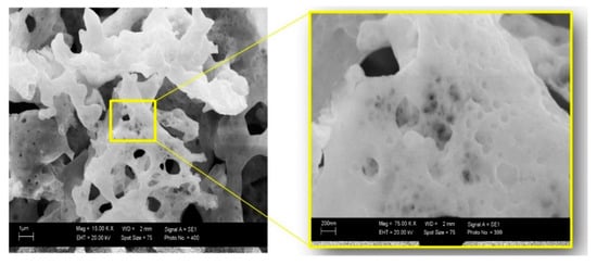
Figure 1.
Scanning electron microscope (SEM) image of freshly synthesized bismuth ferrite at different magnification.
Figure 2a shows a typical X-ray powder diffractogram of bismuth ferrite BiFeO3. All marked peaks characterized hexagonal BiFeO3 with the spatial symmetry R3c, with a small content of the secondary phase indicated in the inset of Figure 2a.
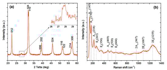
Figure 2.
(a) X-ray diffraction pattern of freshly synthesized BiFeO3; (b) Raman spectrum of BiFeO3 nanoparticles.
The average crystallite size of BiFeO3 nanopowders determined from the Debye–Scherer equation using (012) and (024) planes was 45 nm. The relatively small peak shown in the inset corresponds to Bi24Fe2O39 located at 2θ = 27.97° (PDF 420201) and Bi2Fe4O9 located at 2θ = 28.2° (PDF 250090).
For a more accurate analysis of the structure of the nanopowder, Raman spectra were obtained (Figure 2b). It is known that the rhombohedral structure of R3c causes 13 active combination modes: 4A1 + 9E. The obtained spectrum was characterized by eight modes, four of which belonged to mode A1 and four to E. In addition, there were three overtones in the spectrum. The vibrational modes of Bi atoms were present mainly up to 167 cm−1. Oxygen atoms had strong vibrations at values above 262 cm−1. Fe atoms were mainly involved in modes between 152 and 261 cm−1, but also contributed to the appearance of some modes with higher wavenumbers [27,28]. As noted in [29], the mobility of ferroelectric domains is suppressed in the R3c phase due to the interaction of octahedral antiphase boundaries with non-180° domain walls, which makes a significant contribution to the piezoelectric response. According to the structural analysis, the sample had a hexagonal structure with R3m spatial symmetry. This is due to a feature of high-temperature synthesis, where the R3c→R3m transition is observed in BiFeO3 [30]. This effect was not associated with a change in the cell parameters. Thus, one can expect an enhancement of the piezoelectric properties of BiFeO3 in the R3m phase due to the gradual release of domain walls as the transition proceeds.
The chemical composition of the powder was studied by X-ray photoelectron spectroscopy (XPS) using an AXIS SupraTM X-ray photoelectron spectrometer (Kratos Analytical Ltd., Manchester, UK). The spectra (Figure 3) were calibrated by C1s peak at 284.8 eV.
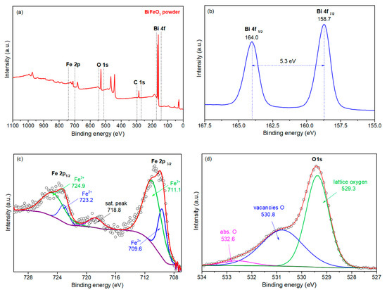
Figure 3.
X-ray photoelectron spectroscopy (XPS) spectra of the BiFeO3 powder: (a) survey spectrum, (b) Bi 4f spectrum, (c) Fe 2p spectrum, (d) O 1s spectrum.
High-resolution XPS spectra are shown in Figure 3a. Peaks Bi 4f7/2 and Bi 4f5/2 were located at ~159.0 eV and ~164.3 eV. In addition, we note that the energy of the spin-orbit splitting of the Bi 4f doublet, which is equal to the energy difference between the Bi 4f7/2 and Bi 4f5/2 peaks, was 5.3 eV, which agrees with the previously reported experimental and theoretically calculated values. Thus, the valence state of Bi ions can be defined as 3+. The spectra of the core levels of Fe 2p are shown in Figure 3c. The asymmetric nature of the peaks and the presence of satellite peaks indicate the presence of iron in the oxidation states Fe2+ and Fe3+. Peak deconvolution delineates the overlapping Fe2+ and Fe3+ peaks. A high-resolution spectrum of the O 1s state was also obtained. A strong peak at 529.7 eV is assigned to the characteristic signal from lattice O. The shoulder, at about 531.5 eV, is assigned to defective O components, such as oxygen vacancies.
The core level peaks of iron, bismuth, and oxygen are highlighted at the survey spectrum (Figure 3a) and were chosen for further processing. The peak of bismuth Bi 4f was characterized with asymmetric duplets of spin-orbit components. The splitting of 5.3 eV and the positions of Bi 4f7/2 and Bi 4f5/2 at 158.7 eV and 164.0 eV (correspondingly) confirmed the presence of oxidized bismuth in the powder (Figure 3b) and the presence of defect states (Figure 3c) [31,32].
Figure 4 shows optical micrographs for the obtained BiFeO3-silicone composites with the different mass loading of BiFeO3. With this approach of obtaining a composite, it is shown that a uniform distribution of nanoparticles is observed over the entire volume of the silicone matrix.
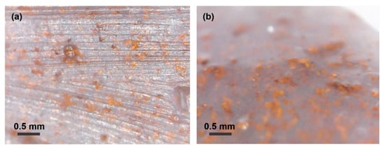
Figure 4.
Optical images of the BiFeO3-silicone composite at 500× magnification. The figures show the filling by the powder in the volume of silicone: (a) sample cross-section, (b) sample top view.
Figure 5a shows an optical micrograph of a cleavage of a BiFeO3-silicone composite film obtained by centrifugation at 500× g magnification. It can be seen from the photograph that a homogeneous film with a thickness of about 230 μm was formed. Figure 5b shows an optical micrograph of a cleavage of the assembled PNG device.
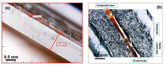
Figure 5.
(a) Optical micrograph of the BiFeO3-silicone composite film at 500× times magnification; (b) optical micrograph of the piezo nanogenerator (PNG) device at 500× magnification.
The typical dependencies of the output voltage on time, measured for PNG with different loading concentrations (10, 30, and 50 mass%) with successive compression and relaxation, are shown in Figure 6. The generated output voltages of unpolarized PNG were measured under periodic vertical compression and relaxation.
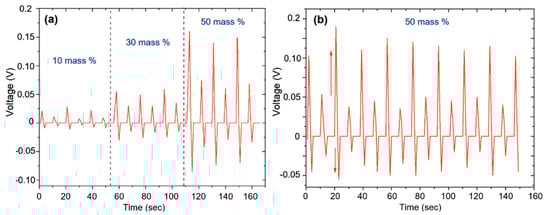
Figure 6.
(a) Voltage generated in the PNG circuit with different concentrations of BiFeO3 loading; (b) the lower graph shows the character of the potential change on the composition for a longer time, where the increase in stress during compression and relaxation is seen.
The output voltages were about 0.028, 0.055, and 0.17 V for PNG loaded with 10, 30, and 50 mass% BiFeO3, respectively. The output voltage gradually increased with an increase in the content of BiFeO3 nanoparticles in the composite of up to 50 mass%, reaching a maximum output voltage of about 0.17 V. The results show that the PNG model obtained in this work demonstrated a performance comparable to the characteristics of other PNGs [33,34]. The observed difference in peak stress values between the states during compression and relaxation can be associated with the difference in the rate of PNG deformation during compression and relaxation.
Figure 7 schematically shows the PNG device’s mechanism of operation. It is known that, without polarization, electric dipoles in BiFeO3 nanoparticles are directed randomly [35].
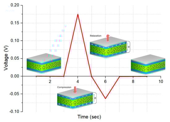
Figure 7.
Schematic representation and electrical response of the PNG operating mechanism.
Without the application of an external mechanical force, the output voltage is not recorded on the PNG since the device is in a state of equilibrium. Upon vertical compression, however, the polarization of the composite changes due to the compression deformation. This leads to the appearance of a piezoelectric potential between the upper and lower electrodes, and the movement and accumulation of free charges on the electrodes. Circuit voltage of PNG during this process with a BiFeO3 nanoparticle concentration of 10 mass% is shown in Figure 7.
The vertical deformation and piezoelectric potential between the two electrodes disappeared at relaxation. The accumulated charges moved in the opposite direction, and a negative electrical signal was generated (Figure 7).
Non-polarized PNG samples produce low voltage values. When PNG is polarized by applying an electric field, the dipoles in BiFeO3 nanoparticles will be aligned along the direction of the applied electric field, and so a significant increase in the output voltage will be observed.
4. Conclusions
The novelty of this work is in the piezoelectric generator, prepared with bismuth ferrite nanosized powder in a silicon solution. The structure and composition of the powder were analyzed in detail. The active layer is represented by BiFeO3-silicone nanocomposite. The active layer thickness was 230 µm. The output voltage depends on the concentration of the powder in the silicon solution. The mechanism of PNG operation is considered. All the results from measurements presented in this paper show that the manufacturing process described yields a suitable piezoelectric material to use for nanogenerators.
Author Contributions
Conceptualization, F.O., S.R. and G.G.; Data curation, N.A.; Formal analysis, V.H.; Investigation, F.O. and S.R.; Methodology, N.A.; Supervision, D.S.; Validation, P.K. and G.G.; Visualization, L.Š.; Writing—original draft, F.O. and S.R. All authors have read and agreed to the published version of the manuscript.
Funding
The research was financially supported by the Ministry of Education, Youth and Sports of the Czech Republic under the project CEITEC 2020 (LQ1601), Czech foundation Agency (GA 19-17457S). CzechNanoLab project LM2018110 funded by MEYS CR is gratefully acknowledged for the financial support of the measurements/sample fabrication at CEITEC Nano Research Infrastructure.
Conflicts of Interest
The authors declare no conflict of interest. The funders had no role in the design of the study; in the collection, analyses, or interpretation of data; in the writing of the manuscript, or in the decision to publish the results.
References
- Liu, Y.Z.; Hao, Z.W.; Yu, J.X.; Zhou, X.R.; Lee, P.S.; Sun, Y.; Mu, Z.C.; Zeng, F.L. A high-performance soft actuator based on a poly(vinylidene fluoride) piezoelectric bimorph. Smart Mater. Struct. 2019, 28, 055011. [Google Scholar] [CrossRef]
- Anton, S.R.; Sodano, H.A. A review of power harvesting using piezoelectric materials (2003–2006). Smart Mater. Struct. 2007, 16, R1. [Google Scholar] [CrossRef]
- Kim, H.S.; Kim, J.H.; Kim, J. A review of piezoelectric energy harvesting based on vibration. Int. J. Precis. Eng. Manuf. 2011, 12, 1129–1141. [Google Scholar] [CrossRef]
- Xu, S.; Qin, Y.; Xu, C.; Wei, Y.; Yang, R.; Wang, Z.L. Self-powered nanowire devices. Nat. Nanotechnol. 2010, 5, 366–373. [Google Scholar] [CrossRef] [PubMed]
- Zhu, G.; Yang, R.; Wang, S.; Wang, Z.L. Flexible high-output nanogenerator based on lateral ZnO nanowire array. Nano Lett. 2010, 10, 3151–3155. [Google Scholar] [CrossRef] [PubMed]
- Hu, Y.; Xu, C.; Zhang, Y.; Lin, L.; Snyder, R.L.; Wang, Z.L. A nanogenerator for energy harvesting from a rotating tire and its application as a self-powered pressure/speed sensor. Adv. Mater. 2011, 23, 4068–4071. [Google Scholar] [CrossRef]
- Choi, M.Y.; Choi, D.; Jin, M.J.; Kim, I.; Kim, S.H.; Choi, J.Y.; Lee, S.Y.; Kim, J.M.; Kim, S.W. Mechanically powered transparent flexible charge-generating nanodevices with piezoelectric ZnO nanorods. Adv. Mater. 2009, 21, 2185–2189. [Google Scholar] [CrossRef]
- Hu, Y.; Zhang, Y.; Xu, C.; Lin, L.; Snyder, R.L.; Wang, Z.L. Self-powered system with wireless data transmission. Nano Lett. 2011, 11, 2572–2577. [Google Scholar] [CrossRef]
- Kwon, J.; Seung, W.; Sharma, B.K.; Kim, S.-W.; Ahn, J.-H. A high performance PZT ribbon-based nanogenerator using graphene transparent electrodes. Energy Environ. Sci. 2012, 5, 8970. [Google Scholar] [CrossRef]
- Qi, Y.; Kim, J.; Nguyen, T.D.; Lisko, B.; Purohit, P.K.; McAlpine, M.C. Enhanced piezoelectricity and stretchability in energy harvesting devices fabricated from buckled PZT ribbons. Nano Lett. 2011, 11, 1331–1336. [Google Scholar] [CrossRef]
- Park, K.-I.; Son, J.H.; Hwang, G.T.; Jeong, C.K.; Ryu, J.; Koo, M.; Choi, I.; Lee, S.H.; Byun, M.; Wang, Z.L.; et al. Highly-efficient, flexible piezoelectric PZT thin film nanogenerator on plastic substrates. Adv. Mater. 2014, 26, 2514–2520. [Google Scholar] [CrossRef]
- Liu, J.; Fei, P.; Song, J.; Wang, X.; Lao, C.; Tummala, R.; Wang, Z.L. Carrier density and schottky barrier on the performance of DC nanogenerator. Nano Lett. 2008, 8, 328–332. [Google Scholar] [CrossRef] [PubMed]
- Briscoe, J.; Stewart, M.; Vopson, M.; Cain, M.; Weaver, P.M.; Dunn, S. Nanostructured p-n Junctions for Kinetic-to-Electrical Energy Conversion. Adv. Energy Mater. 2012, 2, 1261–1268. [Google Scholar] [CrossRef]
- Xu, S.; Hansen, B.J.; Wang, Z.L. Piezoelectric-nanowire-enabled power source for driving wireless microelectronics. Nat. Commun. 2010, 1, 93. [Google Scholar] [CrossRef] [PubMed]
- Dagdeviren, C.; Yang, B.D.; Su, Y.; Tran, P.L.; Joe, P.; Anderson, E.; Xia, J.; Doraiswamy, V.; Dehdashti, B.; Feng, X.; et al. Conformal piezoelectric energy harvesting and storage from motions of the heart, lung, and diaphragm. Proc. Natl. Acad. Sci. USA 2014, 111, 1927–1932. [Google Scholar] [CrossRef]
- Guillon, O.; Thiebaud, F.; Perreux, D. Tensile fracture of soft and hard PZT. Int. J. Fract. 2002, 117, 235–246. [Google Scholar] [CrossRef]
- Eerenstein, W.; Mathur, N.D.; Scott, J.F. Multiferroic and magnetoelectric materials. Nature 2006, 442, 759–765. [Google Scholar] [CrossRef]
- Abrahams, S.C.; Kurtz, S.K.; Jamieson, P.B. Atomic displacement relationship to curie temperature and spontaneous polarization in displacive ferroelectrics. Phys. Rev. 1968, 172, 551–553. [Google Scholar] [CrossRef]
- Wesselinowa, J.M.; Apostolova, I. Theoretical study of multiferroic BiFeO3 nanoparticles. J. Appl. Phys. 2008, 104, 084108. [Google Scholar] [CrossRef]
- Wang, J.; Neaton, J.B.; Zheng, H.; Nagarajan, V.; Ogale, S.B.; Liu, B.; Viehland, D.; Vaithyanathan, V.; Schlom, D.G.; Waghmare, U.V.; et al. Epitaxial BiFeO3 multiferroic thin film heterostructures. Science 2003, 299, 1719–1722. [Google Scholar] [CrossRef]
- Lebeugle, D.; Colson, D.; Forget, A.; Viret, M.; Bonville, P.; Marucco, J.F.; Fusil, S. Room-temperature coexistence of large electric polarization and magnetic order in BiFeO3 single crystals. Phys. Rev. B Condens. Matter Mater. Phys. 2007, 76, 024116. [Google Scholar] [CrossRef]
- Shvartsman, V.V.; Kleemann, W.; Haumont, R.; Kreisel, J. Large bulk polarization and regular domain structure in ceramic BiFeO3. Appl. Phys. Lett. 2007, 90, 172115. [Google Scholar] [CrossRef]
- Dutta, D.P.; Mandal, B.P.; Naik, R.; Lawes, G.; Tyagi, A.K. Magnetic, Ferroelectric, and Magnetocapacitive Properties of Sonochemically Synthesized Sc-Doped BiFeO3 Nanoparticles. J. Phys. Chem. C 2013, 117, 2382–2389. [Google Scholar] [CrossRef]
- Jain, S.R.; Adiga, K.C.; Pai Verneker, V.R. A new approach to thermochemical calculations of condensed fuel-oxidizer mixtures. Combust. Flame 1981, 40. [Google Scholar] [CrossRef]
- Orudzhev, F.F.; Alikhanov, N.-R.; Rabadanov, M.K.; Ramazanov, S.M.; Isaev, A.B.; Gadzhimagomedov, S.K.; Aliyev, A.S.; Abdullaev, V.R. Synthesis and study of the properties of magnetically separable nanophotocatalyst BiFeO3. Chem. Probl. 2018, 16. [Google Scholar] [CrossRef]
- Yang, J.; Li, X.; Zhou, J.; Tang, Y.; Zhang, Y.; Li, Y. Factors controlling pure-phase magnetic BiFeO3 powders synthesized by solution combustion synthesis. J. Alloys Compd. 2011, 509, 9271–9277. [Google Scholar] [CrossRef]
- Chen, P.; Xu, X.; Koenigsmann, C.; Santulli, A.C.; Wong, S.S.; Musfeldt, J.L. Size-Dependent Infrared Phonon Modes and Ferroelectric Phase Transition in BiFeO3 Nanoparticles. Nano Lett. 2010, 10, 4526–4532. [Google Scholar] [CrossRef]
- Yang, Y.; Sun, J.Y.; Zhu, K.; Liu, Y.L.; Chen, J.; Xing, X.R. Raman study of BiFeO3 with different excitation wavelengths. Phys. B Condens. Matter 2009, 404, 171–174. [Google Scholar] [CrossRef]
- Eitel, R.; Randall, C.A. Octahedral tilt-suppression of ferroelectric domain wall dynamics and the associated piezoelectric activity in Pb(Zr,Ti)O3. Phys. Rev. B Condens. Matter Mater. Phys. 2007, 75, 094106. [Google Scholar] [CrossRef]
- Freitas, V.F.; Dias, G.S.; Protzek, O.A.; Montanher, D.Z.; Catellani, I.B.; Silva, D.M.; Cótica, L.F.; dos Santos, I.A. Structural phase relations in perovskite-structured BiFeO3-based multiferroic compounds. J. Adv. Ceram. 2013, 2, 103–111. [Google Scholar] [CrossRef]
- Sobola, D.; Ramazanov, S.; Koneĉnỳ, M.; Orudzhev, F.; Kaspar, P.; Papež, N.; Knápek, A.; Potoĉek, M. Complementary SEM-AFM of swelling Bi-Fe-O film on HOPG substrate. Materials 2020, 13, 2402. [Google Scholar] [CrossRef] [PubMed]
- Kaspar, P.; Sobola, D.; Dallaev, R.; Ramazanov, S.; Nebojsa, A.; Rezaee, S.; Grmela, L. Characterization of Fe2O3 thin film on highly oriented pyrolytic graphite by AFM, Ellipsometry and XPS. Appl. Surf. Sci. 2019, 493, 673–678. [Google Scholar] [CrossRef]
- Li, Z.; Zhu, G.; Yang, R.; Wang, A.C.; Wang, Z.L. Muscle-driven in vivo nanogenerator. Adv. Mater. 2010, 22, 2534–2537. [Google Scholar] [CrossRef] [PubMed]
- Wu, W.; Wang, L.; Li, Y.; Zhang, F.; Lin, L.; Niu, S.; Chenet, D.; Zhang, X.; Hao, Y.; Heinz, T.F.; et al. Piezoelectricity of single-atomic-layer MoS2 for energy conversion and piezotronics. Nature 2014, 514, 470–474. [Google Scholar] [CrossRef] [PubMed]
- Singh, M.K.; Jang, H.M.; Ryu, S.; Jo, M.H. Polarized Raman scattering of multiferroic BiFeO3 epitaxial films with rhombohedral R3c symmetry. Appl. Phys. Lett. 2006, 88, 1–3. [Google Scholar] [CrossRef]


Publisher’s Note: MDPI stays neutral with regard to jurisdictional claims in published maps and institutional affiliations. |
© 2020 by the authors. Licensee MDPI, Basel, Switzerland. This article is an open access article distributed under the terms and conditions of the Creative Commons Attribution (CC BY) license (http://creativecommons.org/licenses/by/4.0/).