1. Introduction
With the rapid increasing demand of the future mobile wireless network, new requirements are put forward for the communication technologies and the applications. The typical application scenarios of the fifth generation (5G) wireless networks consist of enhanced Mobile BroadBand (eMBB), massive Machine Type Communications (mMTC) and Ultra-Reliable and Low Latency Communications (URLLC). For 5G scenarios, the non-orthogonal multiple access (NOMA) has been proposed to increase the system throughput and accommodate massive communication connectivity. Moreover, as opposed to orthogonal multiple access (OMA), the NOMA has low transmission latency and signaling cost. Recently, many NOMA schemes were proposed for 5G, such as the sparse code multiple access (SCMA) [
1], pattern division multiple access (PDMA) [
2], multi-user shared access (MUSA) [
3], low-density signatures (LDS) multiple access [
4], and so on. Among the available NOMA schemes, SCMA is a coding-based multiplexing scheme, which can achieve an obvious increase in spectral efficiency compared to OMA. Its codes are mapped to multi-dimensional sparse codebooks for transmission. Due to the sparsity of the codebook, the message passing algorithm (MPA) [
5] with moderate complexity can be used for multi-user detection (MUD).
Actually, the quality of service (QoS) of NOMA system can be realized by using effective channel coding. Turbo code and low-density parity-check (LDPC) code are studied in many existing NOMA systems for the error correction [
6,
7]. Furthermore, according to the results in [
7], the new radio (NR) LDPC-coded NOMA schemes have almost the same block error rate (BLER) performance as the corresponding Turbo-coded NOMA schemes.
Polar code proposed by Arikan [
8] is the first constructive code that provably achieves the symmetric capacity of binary-input memoryless channels (BMCs). In [
8], Arikan proposed a hard-output successive cancellation (SC) decoder that achieved capacity in the limit of large block length; its performance with finite-length codes was less promising. Tal and Vardy proposed the successive cancellation list (SCL) algorithm whose performance is very close to that of a maximum likelihood decoder [
9]. SCL decoding not only improves the block-error probability of polar code, but also enables one to use modified polar code constructed by concatenating a polar code with a cyclic redundancy check (CRC) code as an outer code [
10,
11]. The simulation results demonstrate that the short-block-size polar code with CRC-aided (CA) SCL has performance advantage over the corresponding LDPC code. Although all of these decoders offer better performance than the SC decoder, none provides the soft outputs essential for turbo-based receivers. Improving the performance of the SC decoder has been at the key of the related research while the generation of soft information. In [
12], the belief propagation (BP) decoder is proposed to decode polar code. It has the advantages of having better performance than the SC decoder and providing soft outputs, but has very high storage and processing complexity. In [
13], the authors developed a low-complexity soft-output version of the SC decoder called the soft cancellation (SCAN) decoder that produces reliability information for both the coded and message bits. The SCAN decoder achieves comparable performance with far less complexity and storage than the BP decoder. However, it cannot achieve the performance of SCL decoder with large list size. According to 3GPP TS 38.212 [
14], polar code is elected as the standard coding technique for the control channel in support of the eMBB service, since it has an excellent error-correction capability based on SCL decoding, especially for short-length packet transmissions.
With the abundant research results of polar code, the application of polar code in NOMA system has also made progress. In [
15], a polar-coded SCMA (PC-SCMA) was proposed, but there is no iteration between the MPA detector and the polar decoder. However, for practical implementations, the iterative detection between the multiuser detector and the channel decoder can improve the performance of the SCMA system. In [
16], a three-stage channel transform structure of the polar-coded NOMA system was proposed, and a joint successive cancellation (JSC) detection and decoding scheme was designed. Although the JSC algorithm improves the performance of the system, it increases the processing latency. In [
17], based on the joint factor graph of SCMA and polar code, the authors have proposed a joint iterative detection and decoding (JIDD) receiver based on SCAN algorithm. The JIDD without inner iterations has best performance when compared with the general iterative detection and decoding (IDD) scheme. It improves the performance of the polar-coded sparse code multiple access (PC-SCMA) system significantly while also saving the complexity costs. However, since the performance of SCAN decoder is not good enough, this JIDD receiver is not ideal. In particular, the performance of the PC-SCMA system is worse than that of LDPC-coded SCMA (LDPC-SCMA) at low code rate. In order to improve the performance of PC-SCMA, the design of the code’s structure and decoding algorithm are feasible.
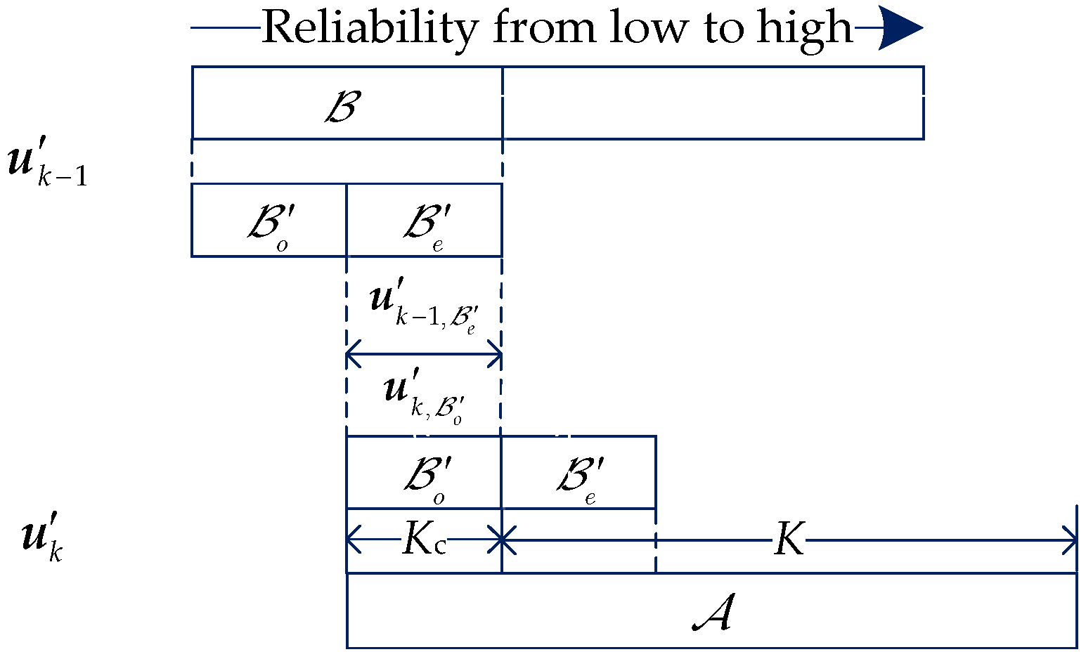
One approach that leads to better performance is to exploit the benefits of long code through spatial coupling. Theoretically, an infinite long codeword chain can be constructed by coupling an infinite number of finite length code blocks (CBs) in a certain structure. For long data sequence transmission, a class of partially information-coupled (PIC) Turbo code [
18] and PIC LDPC code [
19] have been proposed. In these schemes, a transport block (TB) is segmented into several finite-length CBs under the practical decoding complexity and decoding latency constraints. Every two consecutive codes blocks in a TB are coupled by sharing a few information bits. Thus, PIC code can also be regarded as a class of spatially coupled code. PIC polar code was also constructed by systematic polar code in [
20], and a windowed decoder based on CA-SCL algorithm is used for decoding. The TB error rate (TBER) results show that the PIC polar code achieves approximately 0.3 dB coding gain over the uncoupled counterparts for variable code rates. Importantly, the PIC polar code also outperforms the PIC Turbo code at a high
. Basis of this, in this paper, we consider improving the SCMA system by PIC polar code.
Though the code construction of PIC polar code is straightforward, it is very challenging to obtain the promised coding gain over SCMA system compared to [
17]. First, the coding gain of PIC polar code proposed in [
20] is limited. To achieve more coding gain, one straightforward approach is to improve the code block error rate (CBER) of each CB. In the 3GPP meetings, various “assistant bits + basic polar” schemes have been proposed. The idea of “using assistant bits for polar decoding” has been widely adopted, including CA-polar code [
21], joint parity-check and CRC-aided (PCCA) polar code [
22,
23], Hash-CRC polar code [
24], and distributed CRC-aided (DCA)polar code [
25,
26,
27]. The various solutions differ in terms of number of assistant bits, their usage (for error detection and/or correction), positions, and values. Especially, the PCCA-polar code uses the parity check bits for error correction in SCL decoder and gets better performance than other codes. Simultaneously, the Hash-CRC polar code and DCA-polar code have comparable performance to the CA-Polar code. By the way, the systematic polar code that was used in [
20] is CA-polar code. To improve the performance of PIC polar code, PCCA-polar code can be considered as the base code. However, the design of the PCCA-polar code in the systematic form must be resolved. Second, besides the feed-back decoding mechanism based on coupling information bits, the reason why the PIC polar code can obtain excellent performance is that it uses the SCL algorithm for the basic decoder. In iterative receiver, in order to iteratively exchange their messages between the constituent MPA detector and polar decoder, they must be soft-input-soft-output (SISO). Therefore, the hard-output decoding algorithms such as SCL cannot be directly applied to the iterative receiver. The calculation of the extrinsic messages of the coupled polar decoder remains to be resolved. Third, with the coupled polar decoder, increasing the basic decoder’s list size can improve the performance of the system, but it also increases the decoding complexity. On the premise of guaranteeing the performance, the complexity of the receiver should be reduced as far as possible.
On the basis of above discussing, the main contributions of this paper can be summarized as follows:
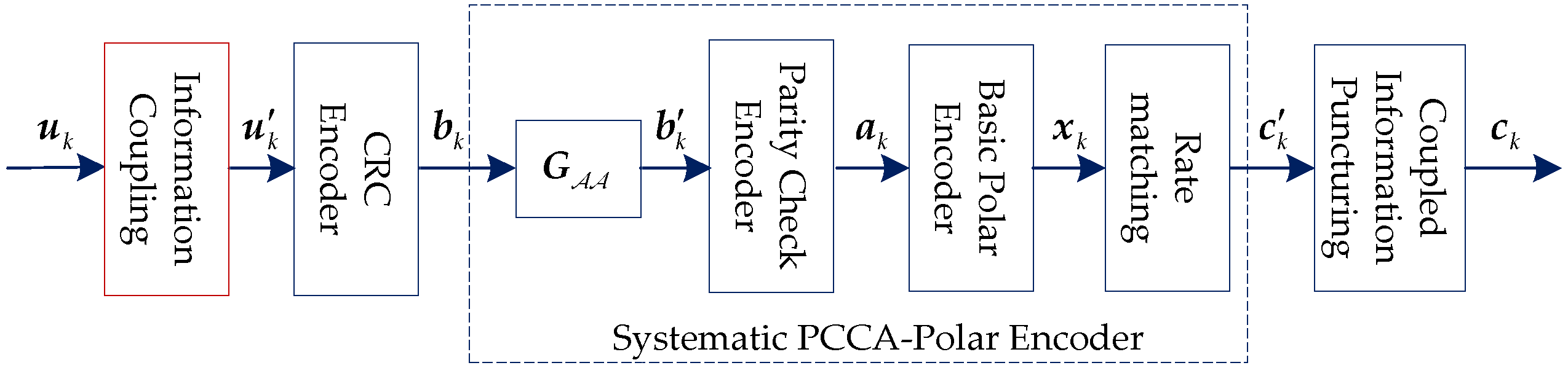
The uplink information-coupled PC-SCMA system is proposed. At the transmitter, channel coding, SCMA mapping, and transmission are all performed based on CB. When the entire TB is received, the receiver performs iterative detection and decoding.
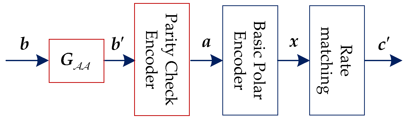
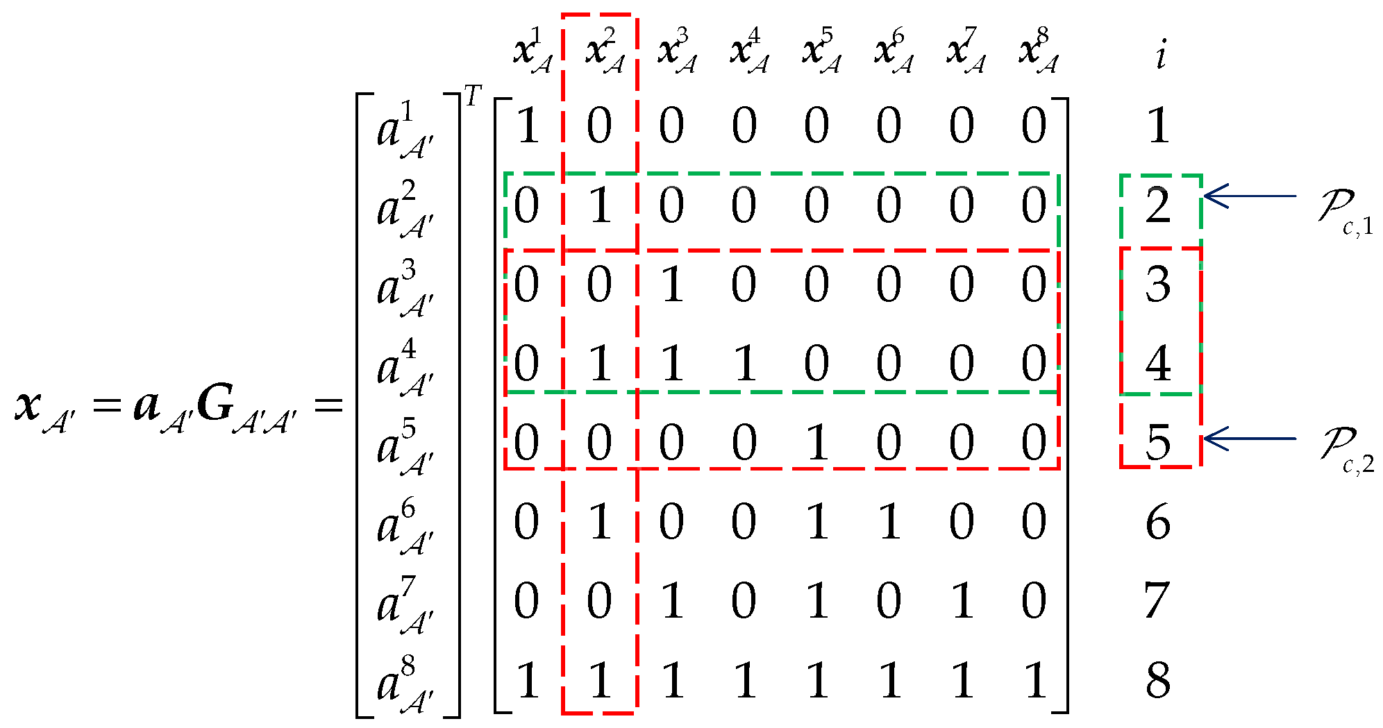
The PCCA-polar code in system form is designed. Then, every two consecutive systematic PCCA-polar code blocks are connected by information coupling technology to form a new type of PIC polar code. For windowed decoder, the list algorithm based on parity check can provide more accurate extrinsic messages for the coupling CBs. In addition, the windowed decoding algorithm is improved for the requirement of iterative system.
An extrinsic messages construction algorithm of coupled polar decoder is proposed. This algorithm enables the coupled polar decoder to exchange extrinsic messages with the MPA detector, and achieving iterative detection and decoding.
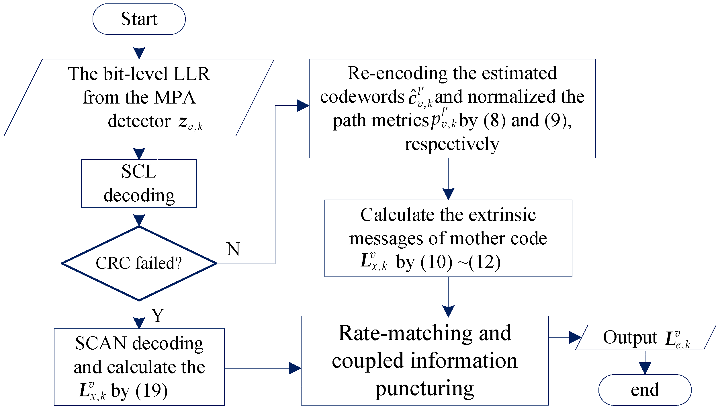
A joint iterative detection and SCL decoding algorithm (JIDS) based on variable list size is designed. During the iteration, those CBs who failed CRC verification improved the performance in the next iteration by increasing the list size, while others maintained a smaller list size. In addition, when all CBs are correctly decoded, the iteration is stopped immediately.
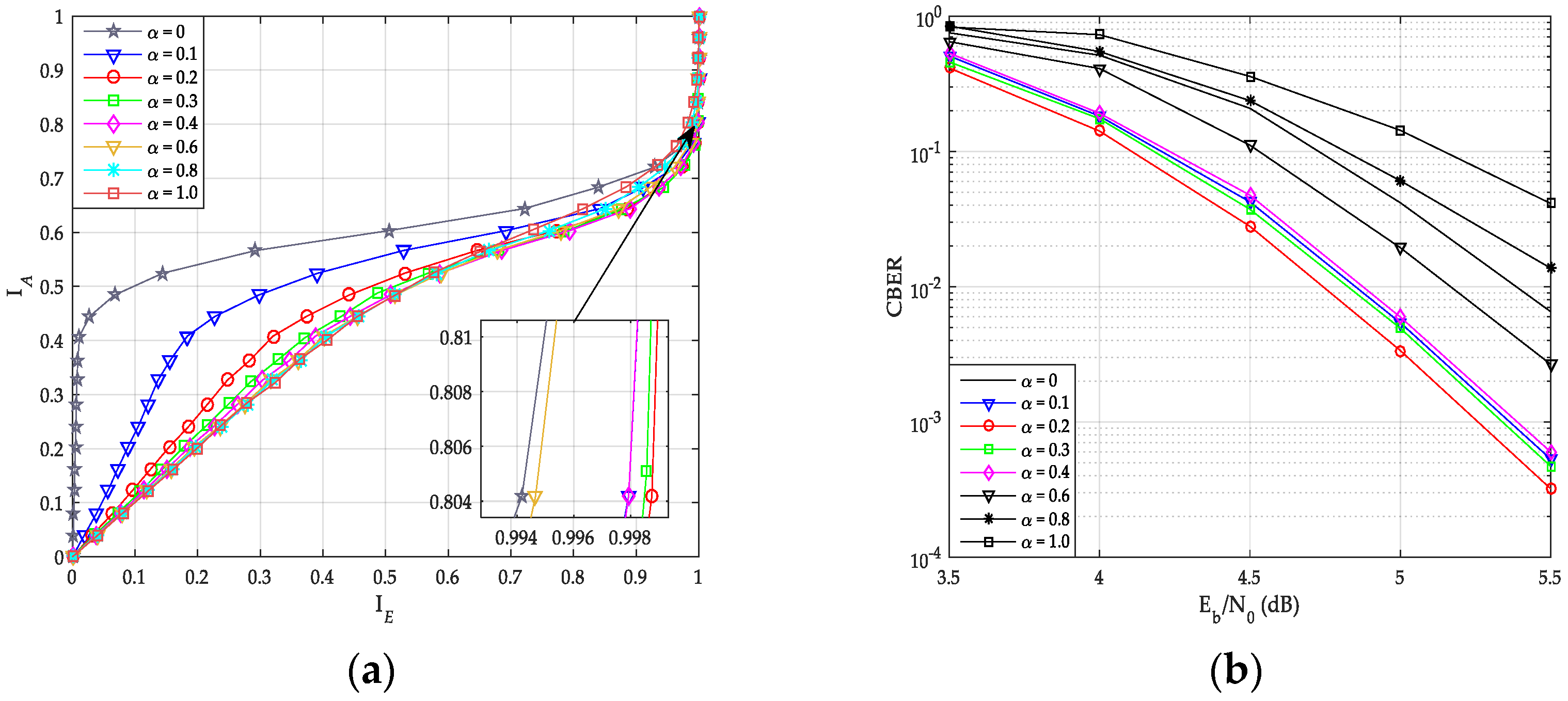
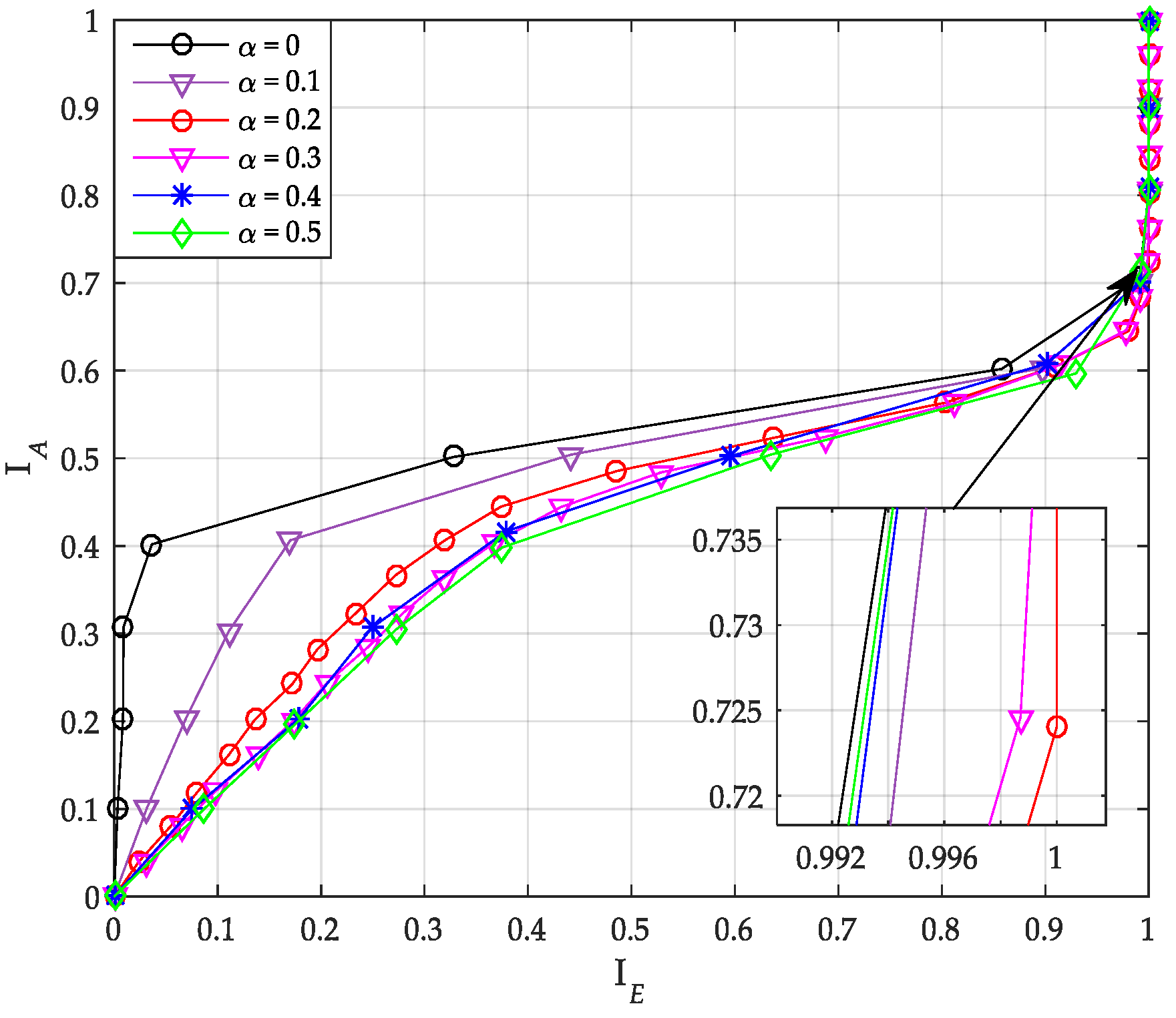
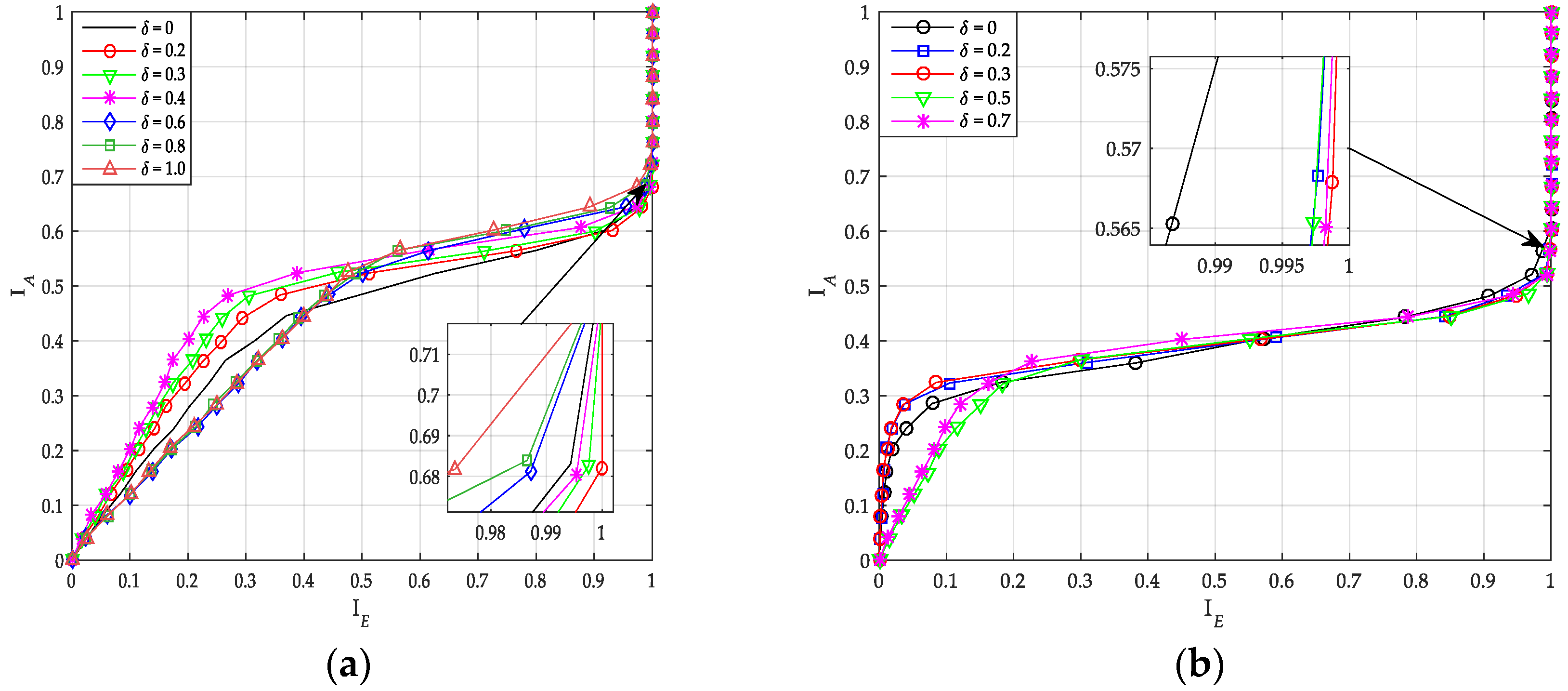
The extrinsic information transfer (EXIT) idea is used to optimize the weight factor of extrinsic messages construction algorithm and coupling ratio of PIC PCCA-polar code.
The rest of this article is organized as follows. In
Section 2, the system model of uplink information-coupled PC-SCMA is described. In
Section 3, the characteristics of systematic PCCA-polar code are analyzed, and the corresponding encoding algorithm is introduced. Then, the construction method of PIC PCCA-polar code is proposed. In
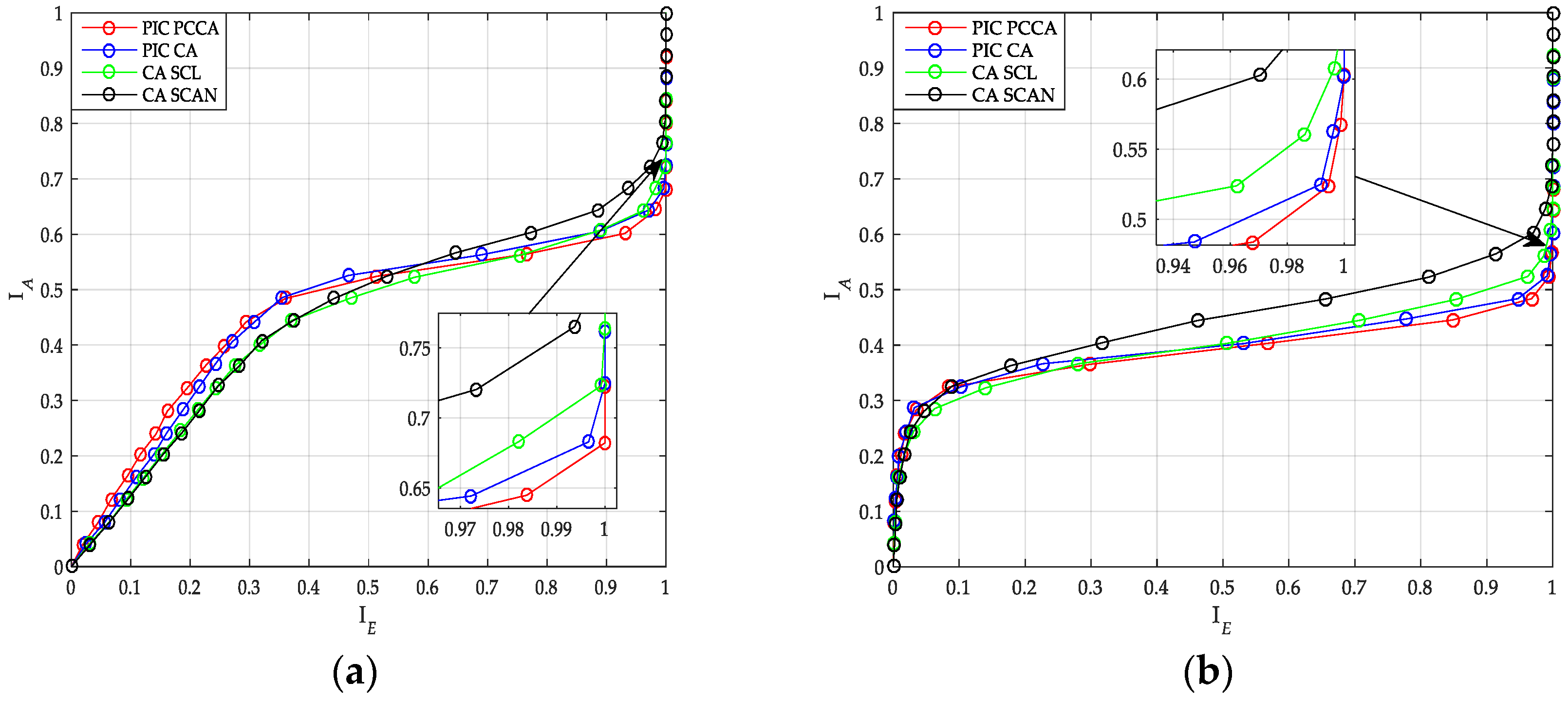
Section 4, a joint iterative detection and SCL decoding algorithm with variable list size is proposed to reduce the complexity. The extrinsic messages of coupled polar decoder are constructed and applied to the receiver. Based on EXIT idea, the transfer characteristics of various polar decoders are analyzed, and the PIC PCCA-polar code is optimized in
Section 5.
Section 6 shows the simulation results and the complexity comparison. Finally, conclusions are reached in
Section 7. To read this article better, we summarize the abbreviations in
Table 1.
2. System Model
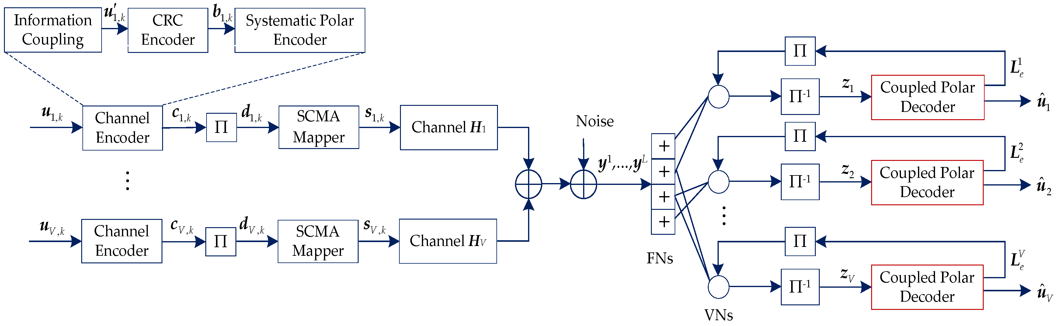
Figure 1 shows the uplink information-coupled PC-SCMA system. In this system, a TB consists of
mutually coupled CB. For CB
k,
, the information bits of
V users
are encoded to
by information coupling, CRC, and systematic encoder. For user
v, its information bits and coded bits are denoted as
and
, respectively. Then, each user’s codeword is interleaved by the random interleaver, which is denoted by
.
Assuming the
V users multiplexed over
M (
M <
V) orthogonal resources. Then, every
bits of
are mapped to a
J-dimensional complex codeword
by SCMA mapper, and the number of SCMA codewords is
. Thus, the overloading factor of SCMA is defined as
and the structure of an SCMA code can be represented by a
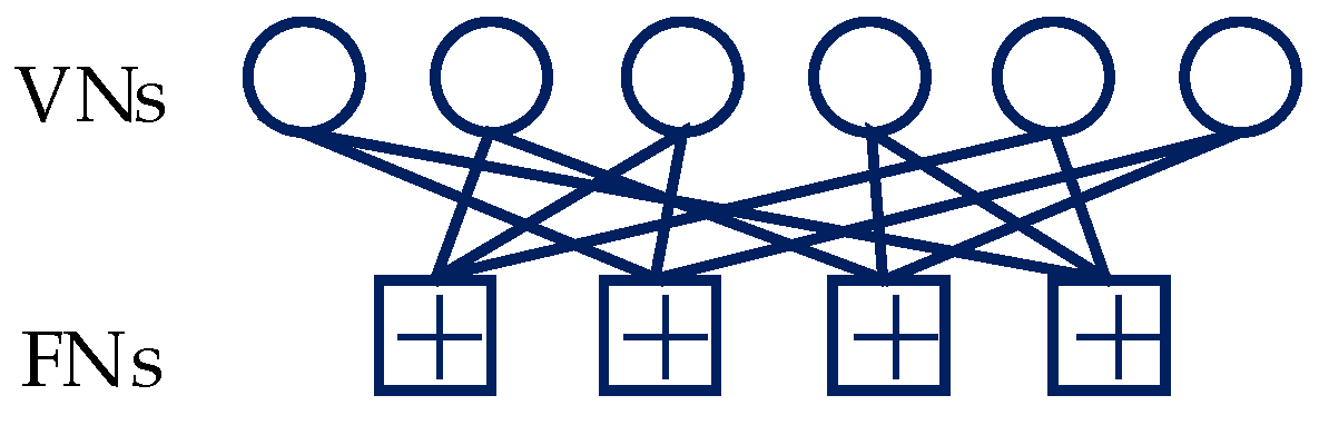
binary mapping matrix
F. As shown in
Figure 2, a SCMA factor graph with six variable nodes (VNs) and four function nodes (FNs) is illustrated, where VNs and FNs represent the users and resources, respectively. The corresponding mapping matrix is denoted as
The iterative detection and decoding are performed after the whole TB is obtained by the receiver. Thus, the number of SCMA codeword
is
. Supposing the channel gains matrix between the base station and user
v at the
l-th block is denoted as
where
represents the channel gain between user
v and resource
j at the
l-th block, and
is a diagonal matrix. Thus, at the receiver, the
l-th received symbols can be described as
where
,
, and
.
is a complex additive white Gaussian noise (AWGN) vector with the mean vector
and covariance matrix
, and
denotes the variance of Gaussian noise.
At the receiver, the received symbols
are decoded by the MPA detector first. The output extrinsic messages of the MPA detector are in the form of log-likelihood ratio (LLR), and de-interleaved to
for user
v, where
. Then, as the a priori information,
is feed into the coupled polar decoder. The output extrinsic messages
is then interleaved and entered into the MPA detector as a priori information. After several iterations, the receiver converges and outputs each user’s decoded information bits
, where
. The information-coupled polar coding is described in
Section 3. In addition, the CRC is used not only for SCL decoding, but also for constructing extrinsic messages and iterative reception. The detailed algorithm is given in
Section 4.
6. Performance Evaluation
In this section, the simulation results are provided to evaluate the block (TB and CB) error rate performance and complexity of the uplink SCMA system over the AWGN channel and Rayleigh fading channel. Assuming there are six users multiplexed over four orthogonal resources, the overloading is 150%. The mapping matrix has already been given in (1), and the corresponding SCMA codebook is designed according to [
30]. Base systematic polar code is constructed by Bhattacharyya parameter-bound method. For each user, the base code length is set to
N = 192, 200, and the code rate is
R = 1/3, 1/2. To ensure that systematic PCCA-polar code and CA-polar code have the same number of assistant bits, the CRC-8 with the generator polynomial
and CRC-11 with the generator polynomial
are used in PCCA-polar code and CA-polar code, respectively. The number of parity check bits
is set to 3. The weight factor
and coupling ratio
are selected according to the values optimized in
Section 5. The number of blocks in a TB and the window size of coupled polar decoder are set to
and
. For the base SCL decoder, the minimum and maximum list sizes are configured as
and
. Additionally, the rate-matching pattern is obtained according to the introduced method of [
14]. As the comparative scheme, the LDPC encoder and rate-matching algorithm used in 3GPP TS 38.212 are employed, where the CRC bits are generated by CRC-11. In addition, the log-Belief Propagation (log-BP) algorithm with 30 inner-loop iterations is used for LDPC decoding. In the receiver, the MPA detection within one inner-loop iteration is employed for MUD, and the number of outer-loop iteration between the MPA detector and channel decoder is set to 5.
6.1. Block Error Rate Performance Comparison
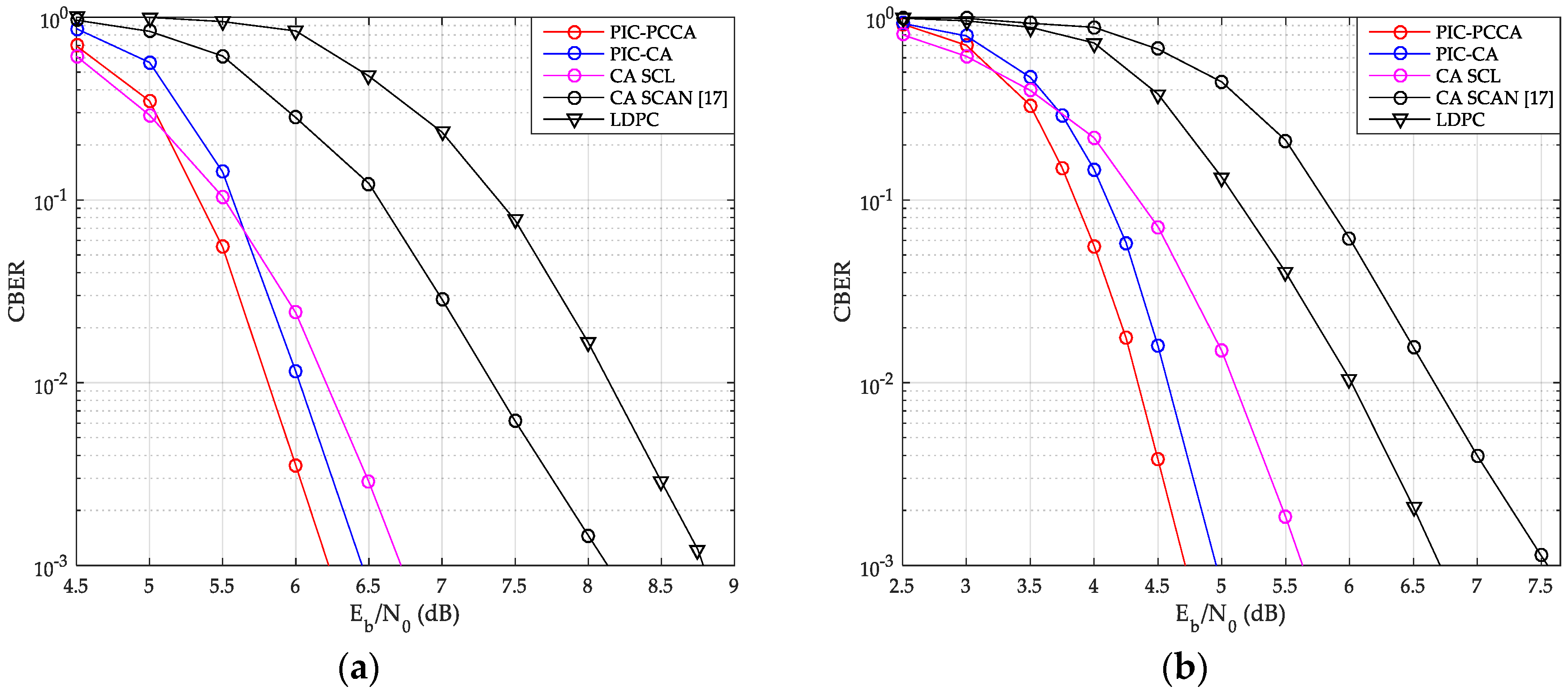
As shown in
Figure 13 and
Figure 14, we have compared the CBER performance of SCMA system with PIC polar codes, uncoupled polar codes, and LDPC code over AWGN and Rayleigh channels.
From these figures, the PIC PCCA-PC-SCMA has the best performance at various code rate and channel configurations, e.g., over AWGN channel, when K = 100 and R = 1/2, the PIC CA-PC-SCMA achieves 0.28 dB coupling gain over the CA (SCL)-PC-SCMA at CBER = 10
−3 as shown in
Figure 13a. In the early stage of each CB decoding, parity-check bits are used to correct errors and save the correct decoding path as far as possible. Therefore, PIC PCCA-polar code also achieved an additional 0.22 dB coding gain compared to PIC CA-polar code over SCMA system. Similarly, for the code rate-1/3, PIC PCCA-PC-SCMA can also obtain corresponding gain as shown in
Figure 13b. However, at the same time, the performance of uncoupled CA-PC-SCMA based on SCAN decoding is the worst among other systems. Since error blocks cannot provide perfect extrinsic messages to adjacent blocks in a TB, adjacent CB can only be decoded at a higher code rate. In particular, in the lower
range, a wrong CB often causes continuous CB errors in a same TB, in other words, these errors are aggregated. Thus, with SCL decoding (for CB), the CBER performance of PIC PC-SCMA systems is worse than that of uncoupled PC-SCMA system. Similarly, we can obtain the same results from
Figure 14.
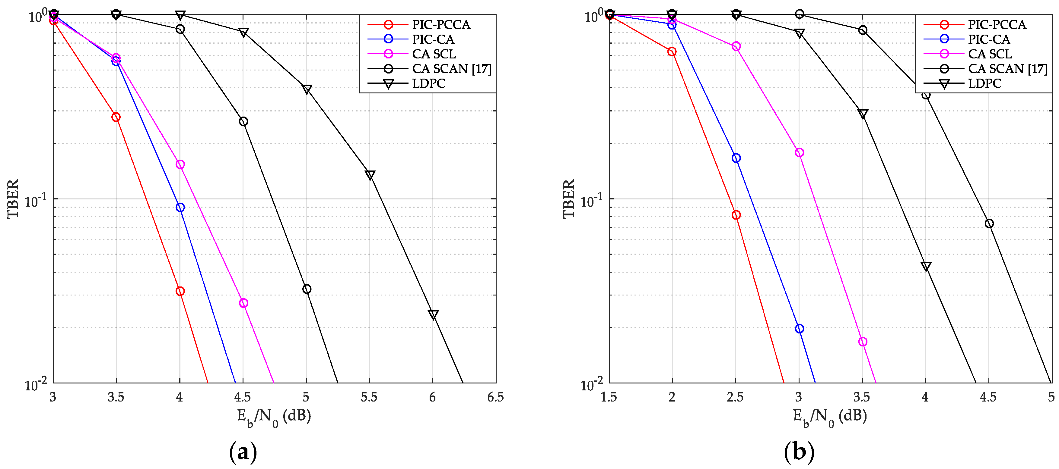
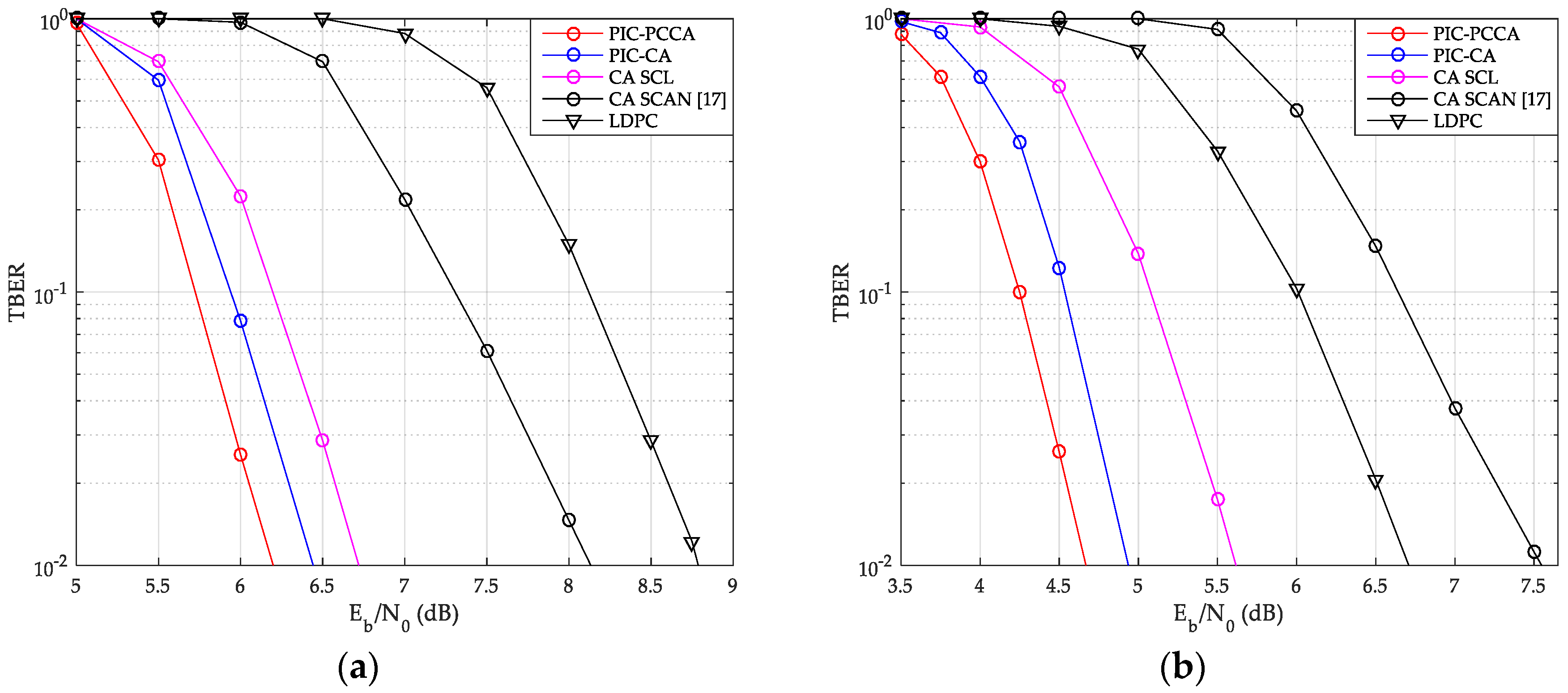
The TBER performance curves of SCMA system are also given by
Figure 15 and
Figure 16. Obviously, we can get results similar to CBER performance. At a low
, although wrong CB may easily cause continuous CB errors in a same TB, the look-back and go-back scheme can also be used to improve the probability of correct decoding once any CB is correctly decoding. PCCA-polar code uses parity check to improve the performance of the base code, thus achieving the goal of reducing TBER. Therefore, even at a low
, PIC PCCA-PC-SCMA also maintains the best TBER performance.
Table 2 shows the specific performance gains of PIC PCCA-PC-SCMA for various code rates and channel configurations at target CBER = 10
−3 and TBER = 10
−2.
6.2. Complexity Analysis
For a PC-SCMA system, the complexity (CB-based) can be given by
, where
is the average number of iterations of JIDS,
is the degree of the SCMA function nodes and
is the average list size per iteration of CB (including feed-back decoding of PIC polar code). Additionally, the list size of the SCAN algorithm is treated as 1. Thus, the complexity of PC-SCMA system can be represented by the average number of iterations
and the average list size
, e.g., the complexity of all kinds of PC-SCMA systems for
K = 100 and
R = 1/2 over AWGN channel is summarized in
Table 3.
On the basis of JIDS algorithm, at a low
, since the high block error rate, a large number of CBs are decoded with large list size. From
Table 2, compared with the uncoupled PC-SCMA with SCL decoder, PIC PCCA (or CA)-PC-SCMA has the higher complexity. Especially, the PIC CA-PC-SCMA system has the highest complexity among other PC-SCMA systems. At a high
, the probability that most CBs can be decoded with a smaller list size in the feed-forward decoding process increases. Therefore, the complexity of the PIC PCCA (or CA)-PC-SCMA system decreases gradually. In particular, with the help of parity check for the base code, PIC PCCA-SCMA can be decoded with fewer outer-loop iterations. Thus, with SCL decoder, the complexity of PIC PCCA-PC-SCMA is lower than that of uncoupled PC-SCMA. By the way, although the PC-SCMA presented in [
17] has the lowest complexity, its performance is far from that of other PC-SCMA schemes.


