Article

Increase of Input Resistance of a Normal-Mode Helical Antenna (NMHA) in Human Body Application

by
Norsiha Zainudin
1,*,
Tarik Abdul Latef
1,*,
Narendra Kumar Aridas
1,
Yoshihide Yamada
2,
Kamilia Kamardin
2 and
Nurul Huda Abd Rahman
2,3
1
Department of Electrical Engineering, Faculty of Engineering, University of Malaya, 50603 Kuala Lumpur, Malaysia
2
Malaysia-Japan International Institute of Technology (MJIIT), Universiti Teknologi Malaysia, 54100 Kuala Lumpur, Malaysia
3
Antenna Research Centre, Faculty of Electrical Engineering, Universiti Teknologi MARA, 40450 Shah Alam, Selangor, Malaysia
*
Authors to whom correspondence should be addressed.
Sensors 2020, 20(4), 958; https://doi.org/10.3390/s20040958
Submission received: 23 December 2019 / Revised: 22 January 2020 / Accepted: 5 February 2020 / Published: 11 February 2020
(This article belongs to the Section Physical Sensors)

Abstract

:
In recent years, the development of healthcare monitoring devices requires high performance and compact in-body sensor antennas. A normal-mode helical antenna (NMHA) is one of the most suitable candidates that meets the criteria, especially with the ability to achieve high efficiency when the antenna structure is in self-resonant mode. It was reported that when the antenna was placed in a human body, the antenna efficiency was decreased due to the increase of its input resistance (Rin). However, the reason for Rin increase was not clarified. In this paper, the increase of Rin is ensured through experiments and the physical reasons are validated through electromagnetic simulations. In the simulation, the Rin is calculated by placing the NMHA inside a human’s stomach, skin and fat. The dependency of Rin to conductivity (σ) is significant. Through current distribution calculation, it is verified that the reason of the increase in Rin is due to the decrease of antenna current. The effects of Rin to bandwidth (BW) and electrical field are also numerically clarified. Furthermore, by using the fabricated human body phantom, the measured Rin and bandwidth are also obtained. From the good agreement between the measured and simulated results, the condition of Rin increment is clarified.

1. Introduction

Biotelemetry is defined as the remote detection and measurement of a condition, activity or function relating to a human or animal [1]. It has an inherent advantage of continuous patient health monitoring through wired and wireless communication. In the present situation, human wearable devices are widely used in the medical field for the purpose of health monitoring and diagnostics [2,3,4,5]. The remote monitoring module is able to track real time information of the physical condition as well as movements. Sensors are integrated into many types of radio wave devices such as capsules, textile and elastic bands, and are implanted or directly adhered to human skin in combination with external devices for wireless monitoring of heart rate [6,7,8], vital signs [9], blood pressure [10,11], body temperature [12], electrocardiograms [13,14,15,16,17] and so on.
A general architecture of an overall remote monitoring system is presented in Figure 1. The monitoring module can transmit the measured data through Bluetooth, WLAN or Wi-Fi to a computer or a mobile device for storage and data analysis.
An antenna is one of the key components in the remote monitoring system. For example, implantable radio wave devices must contain implantable antennas in order to allow in-body communication. However, the implantable antennas face more difficulties and challenges than a wearable antenna for on-body communication due to the complex human tissue conditions. The human body is often referred to as a “lossy” medium due to the performance of antennas that is easily affected by the conductivity (σ) and permittivity (εr) inside the human body [18,19,20,21]. Due to the lossy characteristic of the human body, the radio wave degradation has been very severe. Hence, radio wave devices need to be improved.
One example of the developed radio sensors for health monitoring systems is the wireless capsule endoscopy (WCE) that is equipped with sensing elements and an image capture system. The sensing element consists of a very small antenna that acts as a transmitter and receiver for data transfer from human body. For such a device, it is very critical for the antenna to be very small in size and highly efficient.
Previously, a number of antenna designs have been developed and tested in human phantoms for WCE applications. Some of the options for implantable radio sensor antennas that can be installed in WCE include embedded [22,23,24,25], conformal [26,27,28,29], a planar inverted-F (PIFA) antenna [30], a meander antenna [31], a patch antenna [32] and a spiral antenna [33]. However, a normal-mode helical antenna (NMHA) is found to be a promising candidate due to its high efficiency and small size. Thus, it can be a potential candidate to be implanted inside the human body. The targeted application of NMHA is in the WCE, and the antenna is expected to operate inside the human stomach, fat and skin tissues.
Many researches have been carried out to study the electrical characteristics and performance of NMHAs inside a human body. The self-resonant structures, the effects of material constants to antenna diameters, electric field, magnetic field, input resistance (Rin) and efficiency, and the relations of antenna setting conditions to input impedance and radiation patterns have also been clarified through electromagnetic simulations [34]. However, the effects of σ and εr as the key factors in the human body on the antenna input resistance are yet to be determined.
In previous studies, it was already clarified through simulation that when the conductivity of dielectric material was increased, the input resistance also increased [19]. Another paper also presented that the σ and εr of human tissue are among the factors that have significant effects to the surface impedance, which has further affected the Rin of NMHAs in human tissue [35]. However, the exact relation between them is still unknown. In order to investigate the reason of increase in input resistance, the current distribution data are obtained in this paper and the inverse relation of current amplitude and input resistance is found out. As an influence of the increment of input resistance, the increase in bandwidth is also shown.
In this paper, a systematic study on the correlation of input resistance with other parameters is presented. The dependency of Rin to σ and εr are comprehensively discussed. Additionally, the effects of Rin to bandwidth (BW), electrical field and current distributions are numerically clarified. Furthermore, the measurement of NMHA inside a human body phantom at various body parts with different permittivity and conductivity is presented for analysis and validation. A helical antenna and two human stomach phantoms were fabricated for measurement purposes.

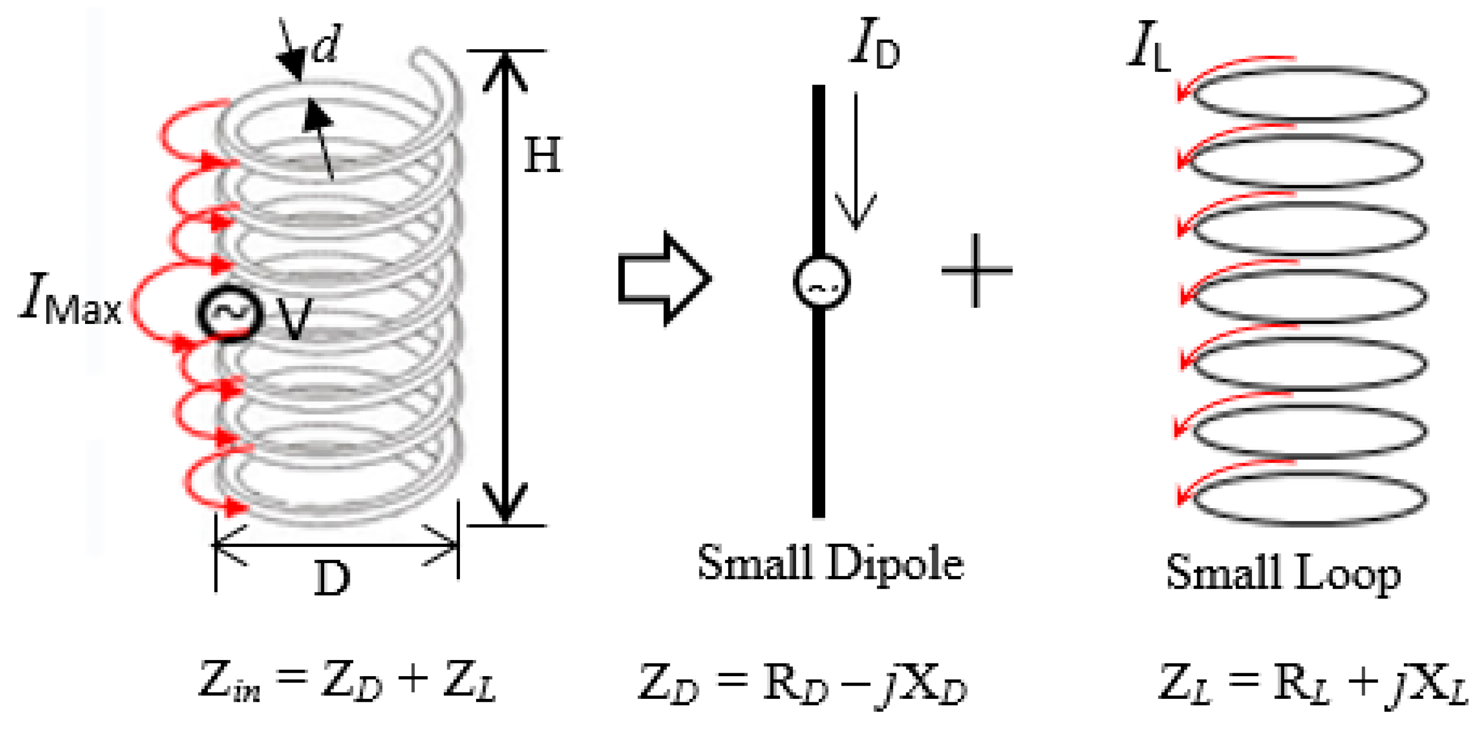
2. Fundamental Equations of NMHA

The NMHA structure and electrical current model are shown in Figure 2. The antenna structural parameters such as the height, diameter and number of turns are indicated by H, D and N, respectively. The spiral current produced by the antenna can be divided into an electric current source from the small dipole, and a magnetic current source of the small loop.
The small dipole and small loop produce input impedance of RrDjXD and RrL + jXL, respectively. The input impedance of the antenna (Zant) is expressed by Equation (1):
Z a n t = R r D + R r L + R r l + j ( X L X D )
The terms RrD and RrL represent the radiation resistance component of the antenna; they correspond to the resistance of the small dipole and resistance from the small loops, respectively. The dissipated resistance due to ohmic resistance of the antenna wire is denoted by Rl.
NMHA is self-resonant when the inductive reactance from the dipole source, XL, is equal to the capacitive reactance from the loop source, XD, as given in Equation (2):
X L = X D
Prior study has established the self-resonant equation in human body conditions [36], as in Equation (3) where the left and right side terms correspond to the XL and XD, respectively.
μ r ε r 600 π × 19.7 N ( D λ g ) 2 9 D λ g + 20 H λ g = ε r μ r 125 H λ g π N ( 1.1 H λ g + D λ g ) 2
The wavelength inside the material, λg, is calculated as Equation (4). The equation is dependent on the wavelength in free space, λo:
λ g = λ o ε r μ o
where εr is the dielectric permittivity of human body part and µo is permeability in free space.
In a self-resonant situation, the antenna impedance becomes a pure resistance as shown in the next expression:
R a n t = R r D + R r L + R l
In the case of in-body conditions, the input resistance of the body Rin(body) can be expressed as shown in Equation (6):
R i n ( b o d y ) = R a n t + R l o s s ( b o d y )
where Rloss(body) represents the additional resistance produced by the conductivity (σ) of a human body.

3. Electromagnetic Simulation of NMHA in Human Body Conditions

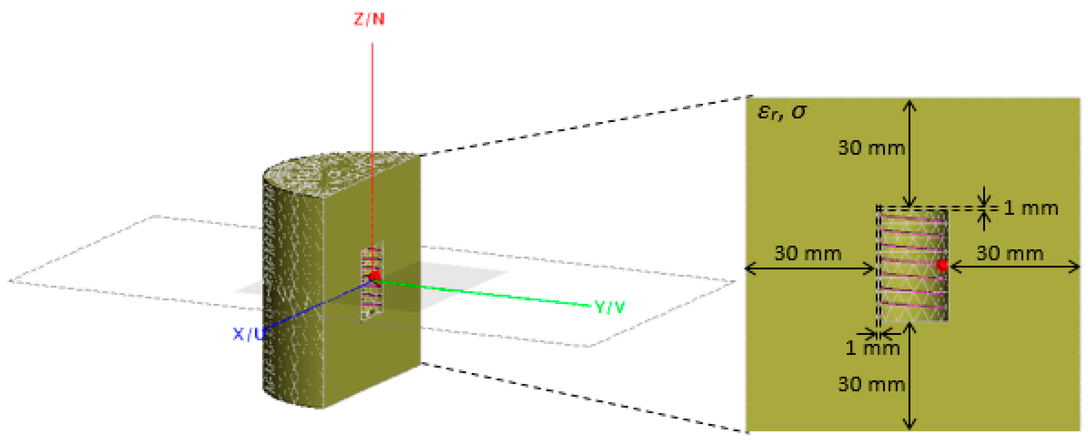
3.1. Simulation Model

The dielectric environment is modeled using the electromagnetic simulator FEKO 2018. The NMHA is embedded inside the center of a homogenous cylindrical human body phantom as illustrated in Figure 3. The antenna is covered with a cylindrical capsule to ensure non-direct contact with the dielectric material. An air gap is set to be 1mm between the antenna and the body phantom.

3.2. Simulation Parameters

The simulation parameters are summarized in Table 1. The operating frequency of 402 MHz is selected based on the medical implant communication service (MICS). Since this study is related to biomedical applications, the implanted antennas are assumed to operate in the frequency band of 402–405 MHz, which is recommended by the European Radiocommunications Committee (ERC) for ultra-low-power active medical implants [37].
The permittivity values of εr1 = 67.5, εr2 = 11.6 and εr3 = 46.7 [38] correspond to a human stomach, fat and skin, respectively. The conductivity of the human body is simulated from σ = 0 to σ = 1.1 in order to study the effect on the input resistance.

4. Simulation Results

The NMHA configuration as shown in Figure 3, with the selected parameters as listed in Table 1, was simulated. The antenna parameters such as the self-resonant structure, input resistance, current distribution, voltage standing wave ratio (VSWR) and bandwidth were analyzed from the simulation results.

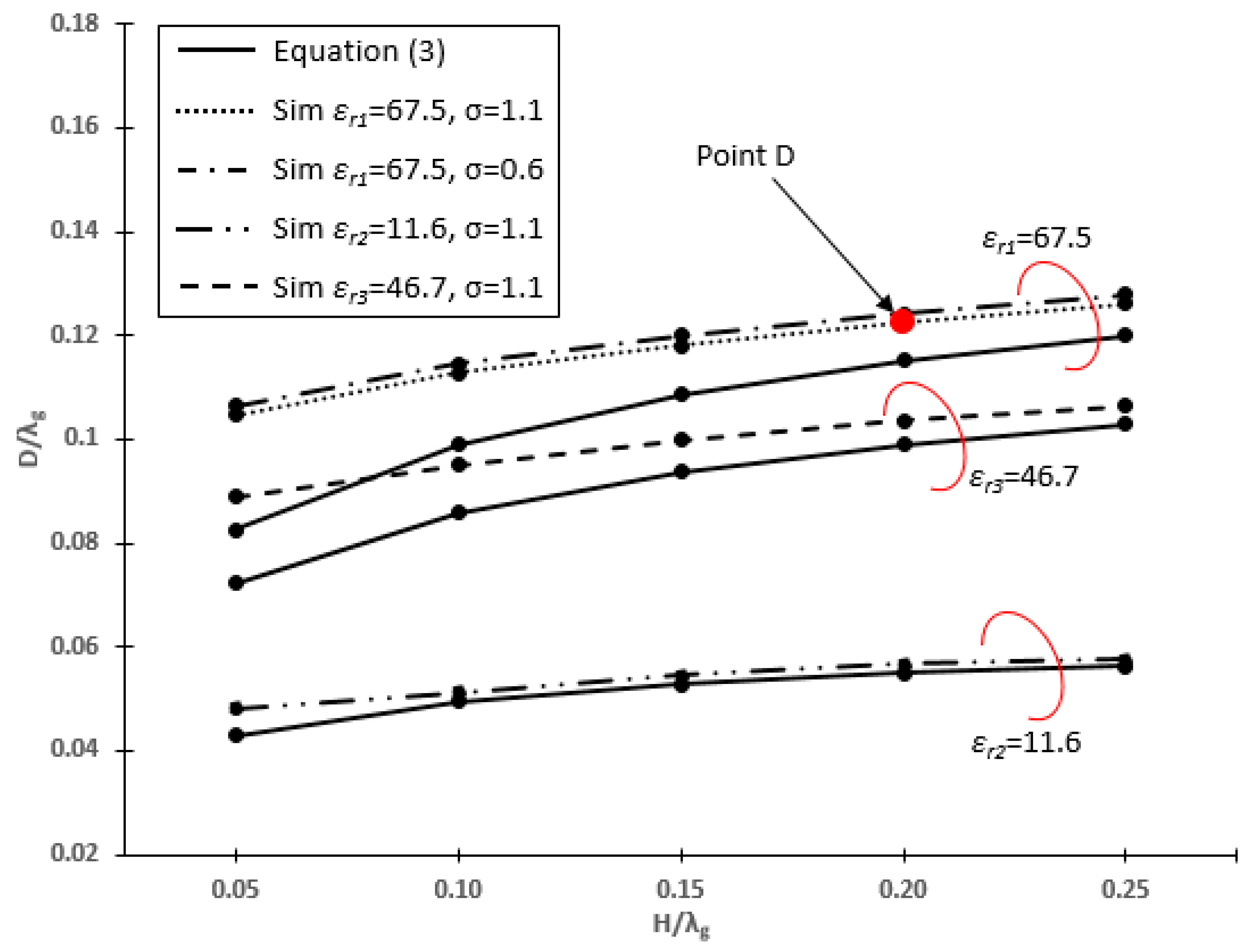
4.1. Self-Resonant Structure

Figure 4 shows the self-resonant structures of the NMHA in human body equivalent mediums, which are stomach, fat and skin with εr1 = 67.5, εr2 = 11.6 and εr3 = 46.7, respectively. At this point, the Zin is pure resistance and the diameter, D, can be obtained by fixing the value of the height, H, and the number of the turn, N. The D and H will be analyzed in terms of D/λg and H/λg, which are normalized to wavelength in the human body (λg).
Based on the figure, there is no significant difference in the resonant curve for different values of σ. Thus, it can be considered that conductivity does not change the dimensions of NMHA, in terms of D and H. Therefore, the conductivity of the human body tissues is considered to have no effects on the resonant condition of NMHA. For further analysis, the NMHA structure at point D is selected, which represents the NMHA structure in human stomach tissue (εr1 = 67.5) for σ = 1.1 S/m that is suitable for WCE application. At this point, λg = 90.77 mm, H/λg = 0.2 mm and D/λg = 0.1209 mm.

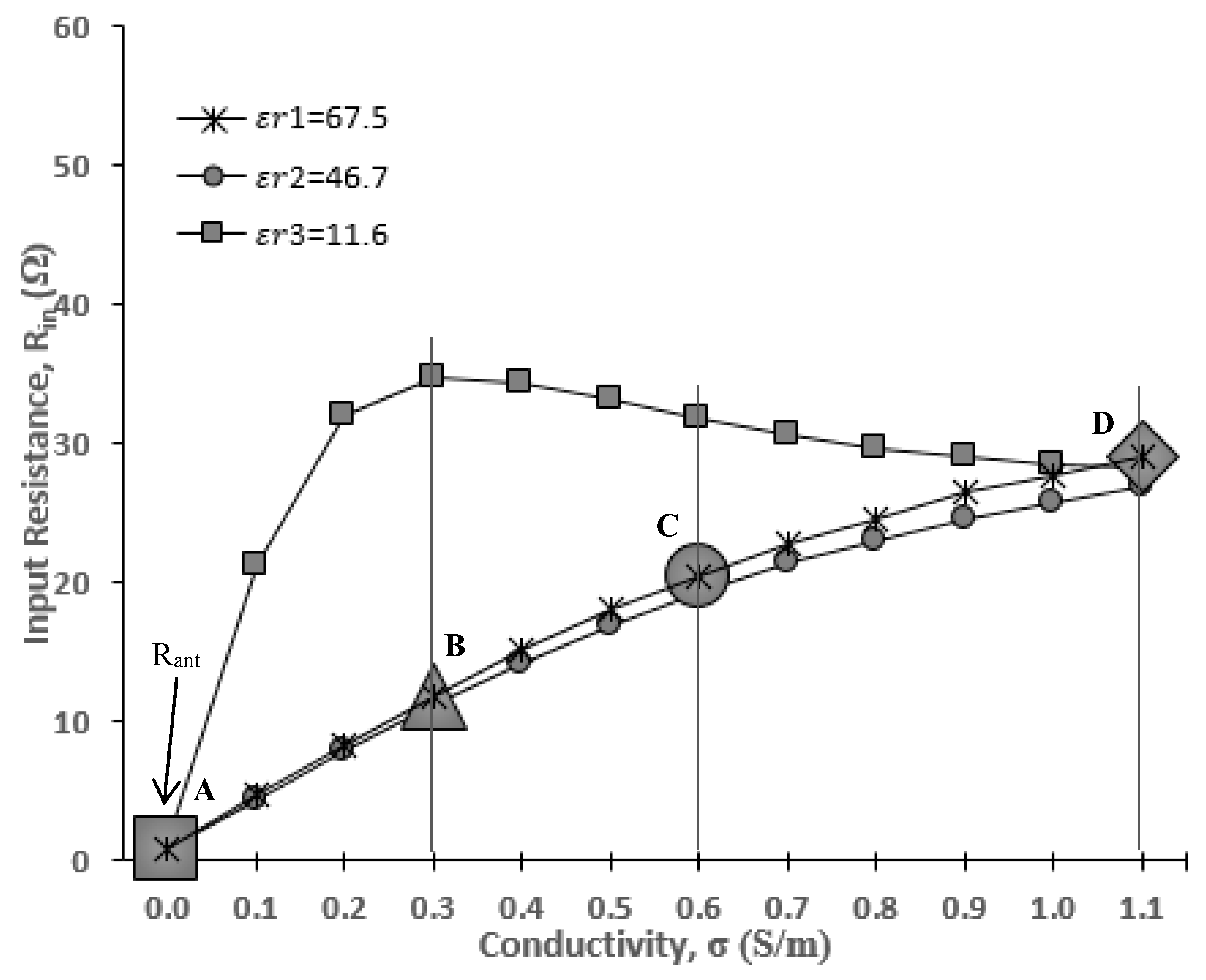
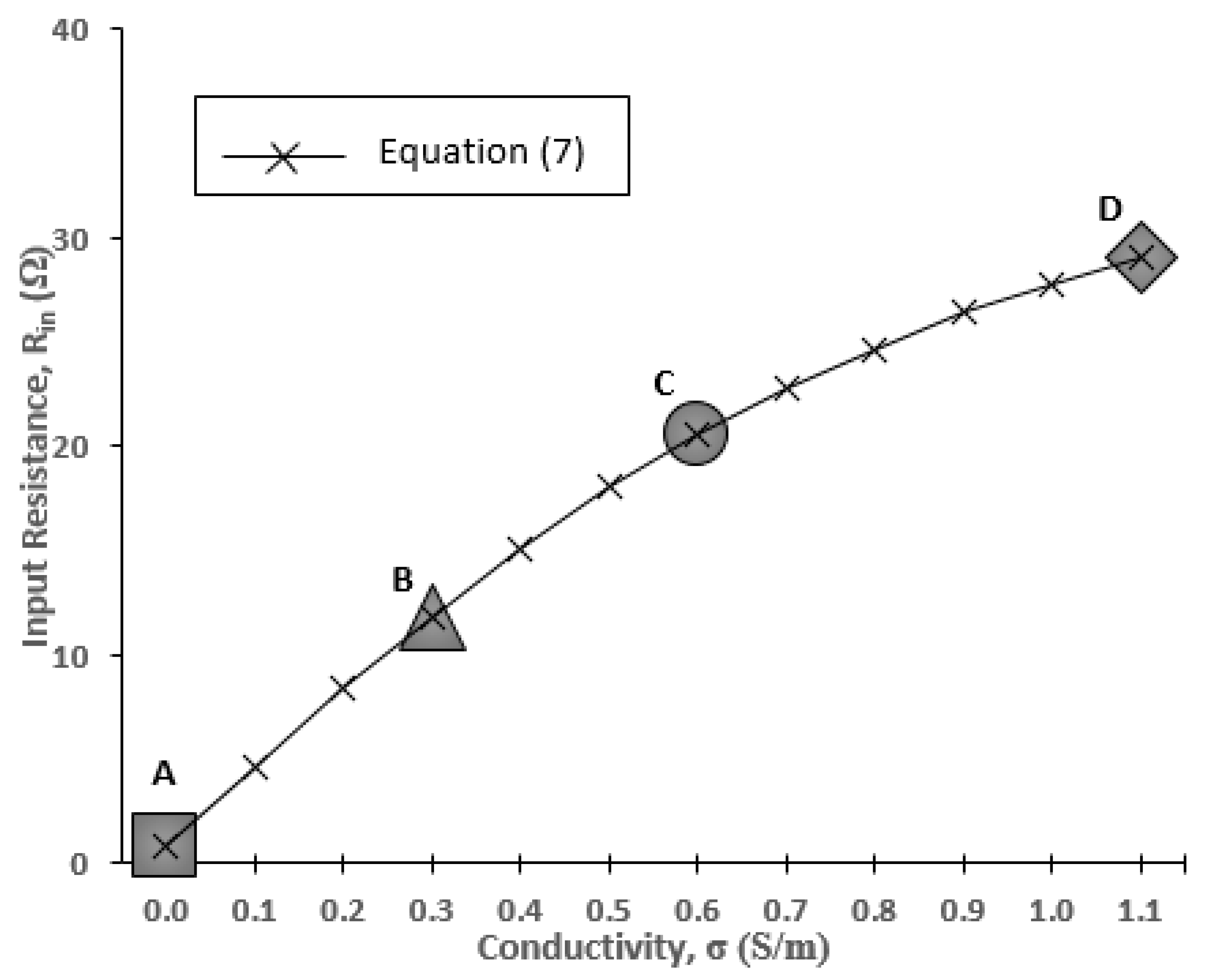
4.2. Input Resistance
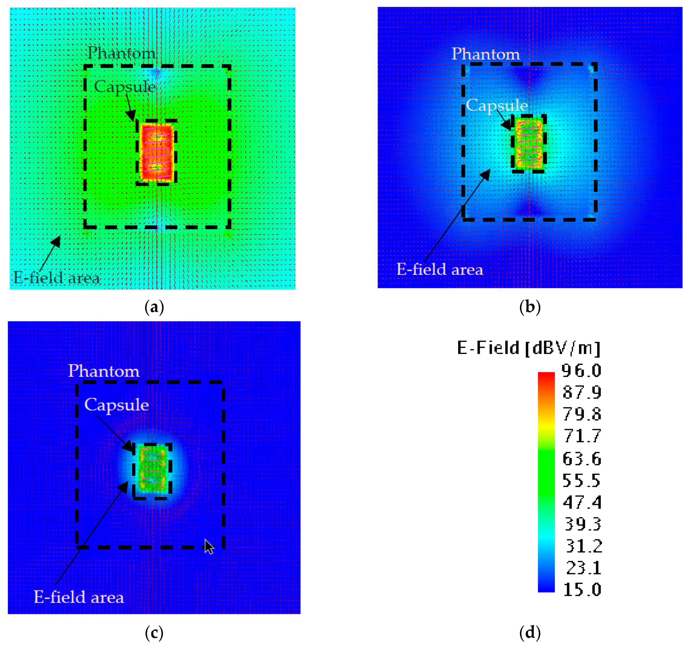
In this section, the antenna input impedance is calculated. Figure 5 shows the Smith chart display of the input impedance at the resonant point. At this point, the input impedance becomes pure resistance (Rin) at the resonant frequency, fo = 402 MHz. The solid black line and dashed line indicate the values of input resistance at σ = 0 and σ = 1.1, respectively. It is observed that the input resistance is increased from σ = 0 (Rin = 0.8 Ω) to σ = 1.1 (Rin = 29 Ω). To see the trends more clearly, Figure 6 is plotted, elaborating data of Rin at more discrete points of σ.
Based on Figure 6, the antenna input resistances at σ = 0 are Rin(εr1) = 0.8 Ω, Rin(εr2) = 1.1 Ω and Rin(εr3) = 0.8 Ω. These values are very small and almost equal to 0 Ω. With reference to Equation (5), this explains the input impedance behavior that is almost equal to the input resistance of the body Rin(body) with very minimal existence of antenna input resistance. At the same time, at higher σ, a significant increase in the Rin is recorded. For stomach and skin, the Rin experiences a steady rise as σ increases. A different tendency is shown in the lower permittivity condition (fat, εr = 11.6), where the Rin rapidly increases from σ = 0 to σ = 0.3 and then stays constant at σ = 1.1. The input resistance in the human stomach with a dielectric permittivity of εr = 67.5 will be explained specifically in this paper at points A, B, C and D, which represent the conductivity of σ = 0, σ = 0.3, σ = 0.6 and σ = 1.1, respectively. From Figure 6, the input resistance at points A, B, C and D is Rin(σ=0) = 0.8 Ω, Rin(σ=0.3) = 11.8 Ω, Rin(σ=0.6) = 20.5 Ω and Rin(σ=1.1) = 29 Ω, respectively.
As a summary for the dependency of Rin on σ, it is clear that the input resistance has increased with the increase of the σ value. For the dependency of εr on the input resistance, further study of other data such as electric field distributions are needed.

4.3. Electric Field

In order to investigate the changes in Rin, the effects of electric field distribution shall be examined. The changes in the near field distributions are shown in Figure 7a–c. When the conductivity is increased, the electric field distribution areas and electric field strengths are decreased. However, this information is not sufficient to explain the increment of Rin. Hence, the current distributions on the antenna should be investigated.

4.4. Current Distribution
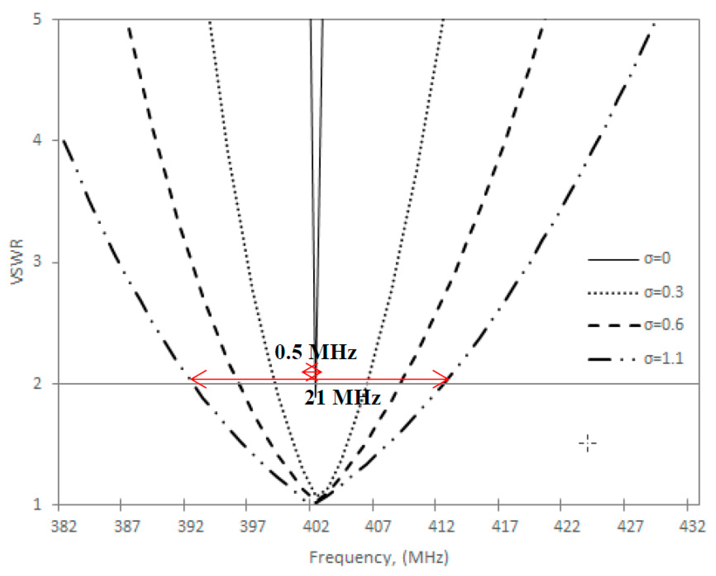
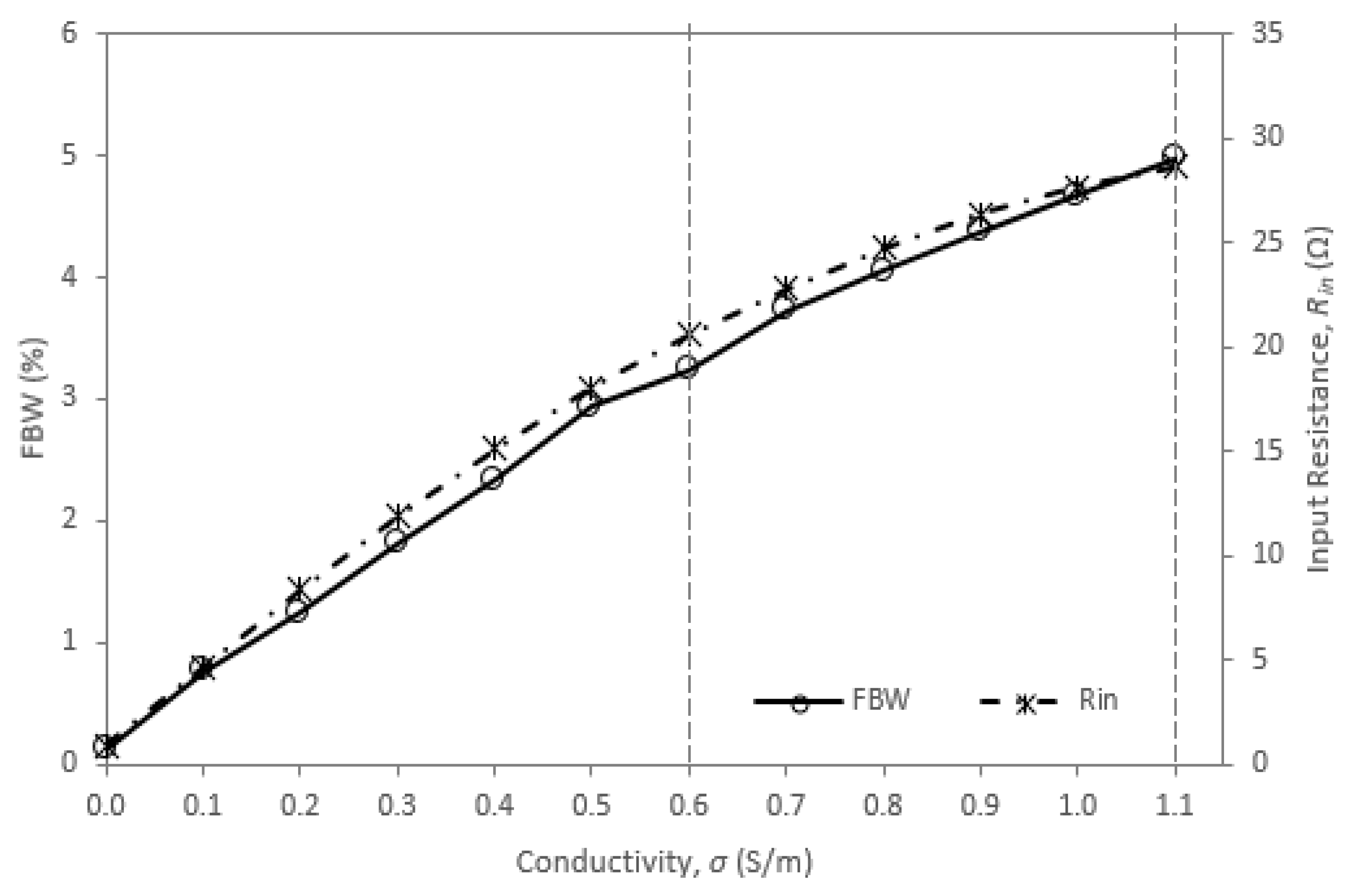
The current distribution along the wire is analyzed as shown in Figure 8. The Maximum current (Imax) is observed at the center of the wire (red color), approximately at H/2. The current distribution is tapered towards the end of the antenna, where I = 0 A (dark blue color). A strong current area is concentrated at the center of the antenna for εr1 = 67.5, σ = 0 as compared to σ = 0.3, σ = 0.6 and σ = 1.1. The blue color along the wire in σ = 0.3, σ = 0.6 and σ = 1.1 shows that a very low current is distributed at higher σ.
For further analysis, the Imax for εr1 = 67.5 with different values of σ is plotted in Figure 9.
As seen in the graph, the maximum current at point A, B, C and D is Imax(σ=0) = 1.12 A, Imax(σ=0.3) = 0.08 A, Imax(σ=0.6) = 0.05 A, and Imax(σ=1.1) = 0.03 A, respectively. It is obviously shown that the Imax is reduced as the value of σ increases.
Because Imax changes with respect to the change of σ, Rin can be calculated by Equation (7). It is noted that the input voltage, V was set to be 1 V:
R i n = V I max
The calculated Rin by Imax results are plotted in Figure 10. From the graph, it is clearly shown that the calculated Rin agree well with the simulated Rin for εr1 = 67.5, as illustrated previously in Figure 6. The good agreement of Equation (7) and the results of Rin in Figure 6 demonstrates the reason for the increase of Rin. It can be summarized that Imax is inversely proportional to Rin as σ increases. However, detailed discussion on the Imax reduction in lossy material will be made in future works.

4.5. Bandwidth

The bandwidth can be expressed by Rin as follows. The Rin and antenna Q factor are related by Equation (8):
Q = X L R i n
Here, XL is the inductive reactance as shown in Equations (2) and (3). Then, the bandwidth (BW) at the specified VSWR is expressed by Equation (9):
B W = V S W R 1 Q V S W R
As a result, BW becomes proportional to Rin and is dependent on conductivity as expressed by Equation (10):
R i n ( σ ) B W ( σ )
The simulation results of the antenna VSWR characteristics for εr1 = 67.5 are shown in Figure 11. It is shown that VSWR increases as the conductivity increases for εr1 = 67.5 (VSWR(σ=0) = 0.5 MHz to VSWR(σ=1.1) = 21 MHz).
Figure 12 explains the relation of the simulated Rin to the fractional bandwidth (FBW) by conductivity. The graph clearly shows the direct proportional characteristics of FBW to Rin as in Equation (10).

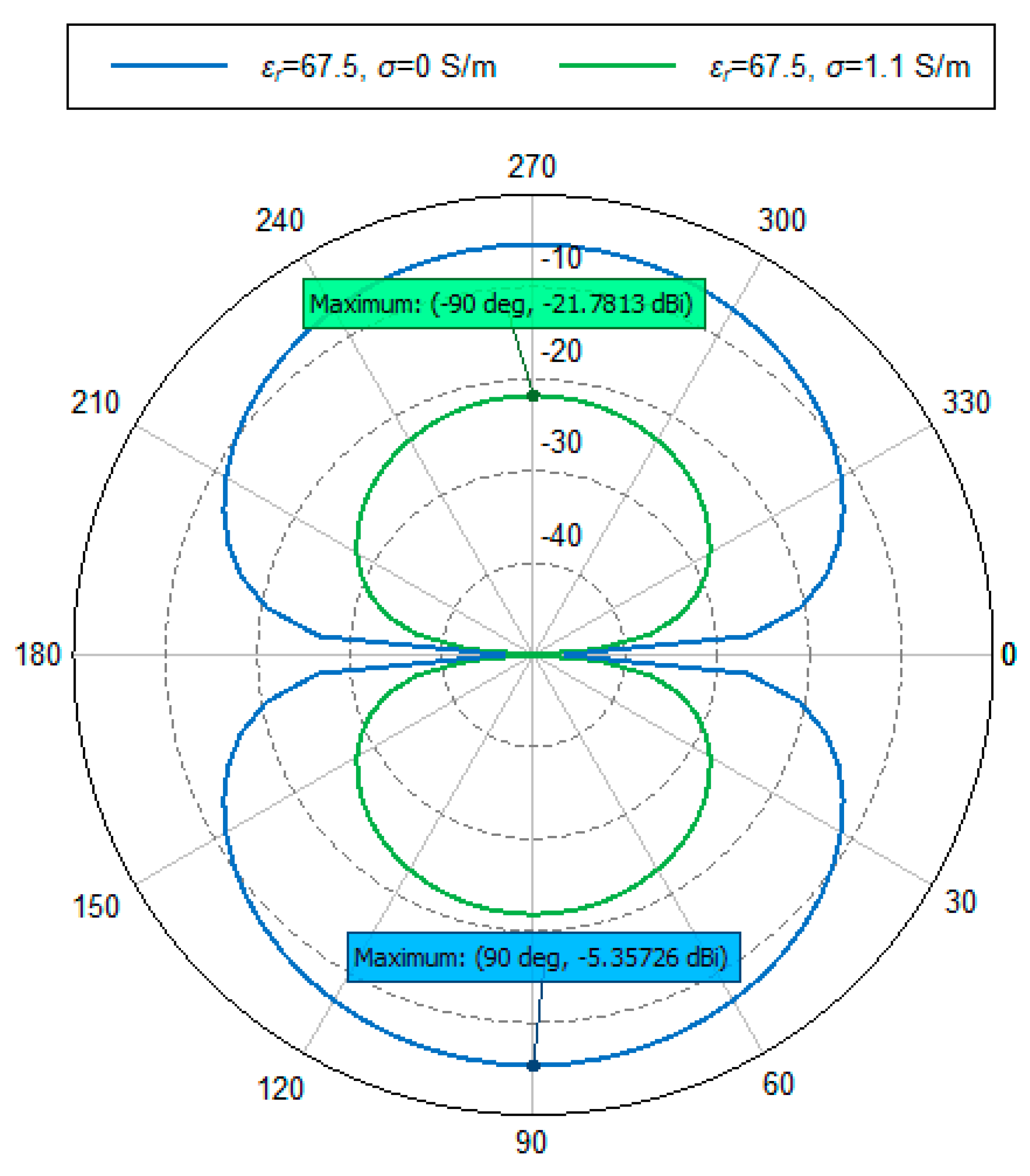
4.6. Radiation Pattern

The radiation pattern is a graphical representation of the radiation (far-field) properties of an antenna. The simulated radiation patterns for εr1 = 67.5, at point A (σ = 0) and point D (σ = 1.1) are shown in Figure 13. Antenna gain (GA) values at point A and point D are −5.357 dBi and −21.78 dBi, respectively.
When Ra is antenna resistance, and Rin(σ) is the input resistance in the human body, then antenna efficiency, ηa, can be simplified to below expression:
η a = R a R i n ( σ )
Then, antenna gain, GA, can be expressed by the next equation:
G A = η a + Γ + G D   ( dBi )
Here, GD is the antenna gain for a short dipole antenna and the value is 1.8 dBi, where, Г is the reflection of the material surface. The calculation of ηa and GA values for εr1 = 67.5, σ = 0 and σ = 1.1 of Figure 13 are shown in Table 2.
In Table 2, GA value for both σ = 0 and σ = 1.1 become almost identical to the ηa value. The reason is perhaps that the Г is around 2 dB, thus Г and GD is cancel each other out. This explains the close values for GA and ηa.

5. Measurement Setup

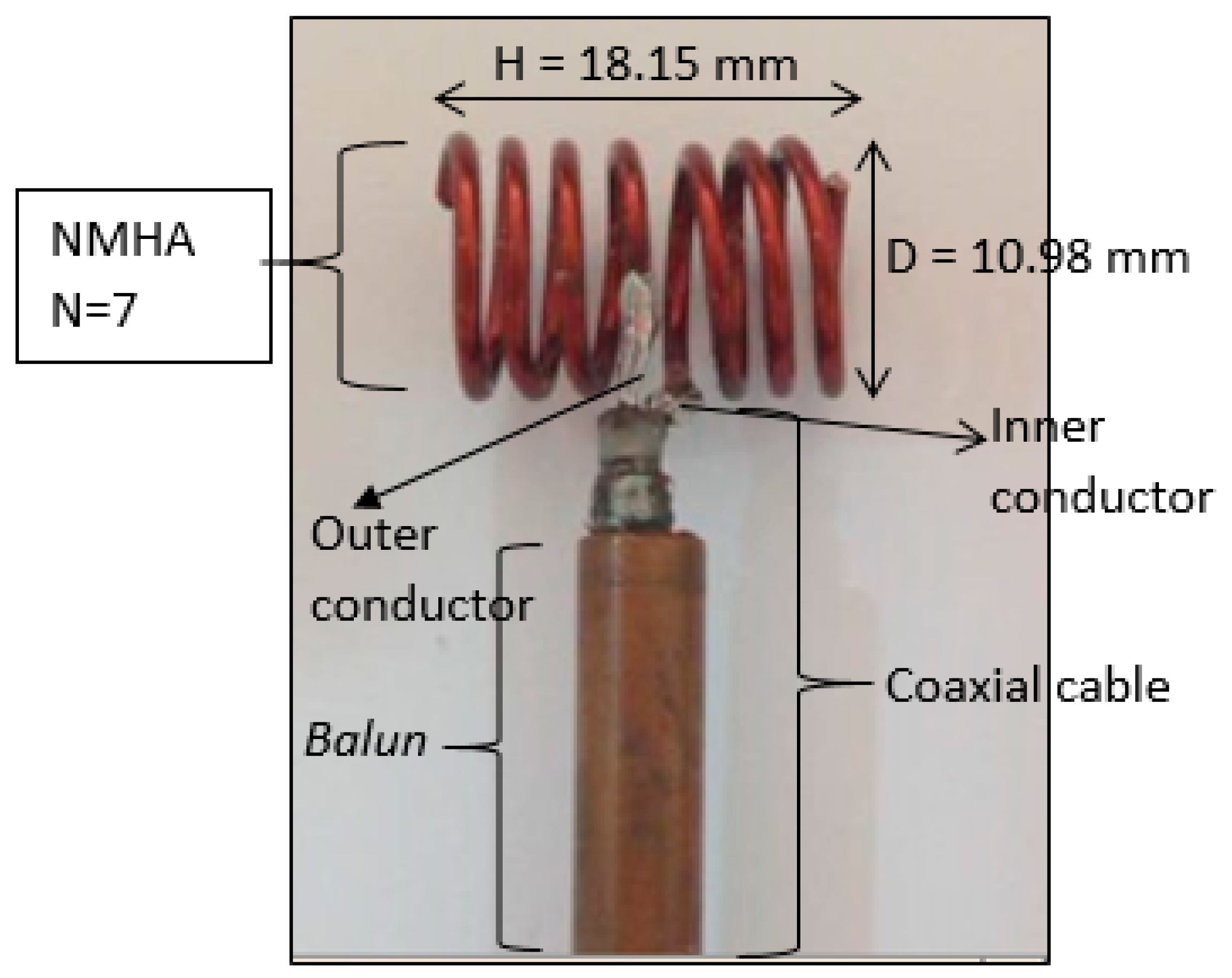
5.1. Antenna Fabrication

For measurement purposes, a NMHA was fabricated. A Metallic copper wire with a conductivity of 58 × 106 (S/m) was used to construct the antenna. In order to fabricate the antenna, ‘point D’ was selected at H/λg = 0.2 as shown in Figure 4. Hence, the H and D of the antenna were determined and the fabricated antennas are shown in Figure 14.
Because the NMHA size is very small, antenna performance is affected by the leakage current on the coaxial cable. In order to suppress the leakage current on the outside of the outer conductor, NMHAs are soldered to a balun. By attaching the balun, leakage current is sufficiently reduced and NMHA performance is correctly achieved. In this mode, the currents on the inner conductor and on the inside of the outer conductor are equal in magnitude and opposite in direction.

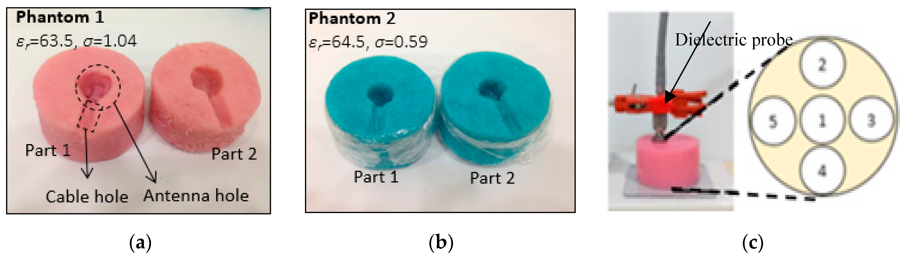
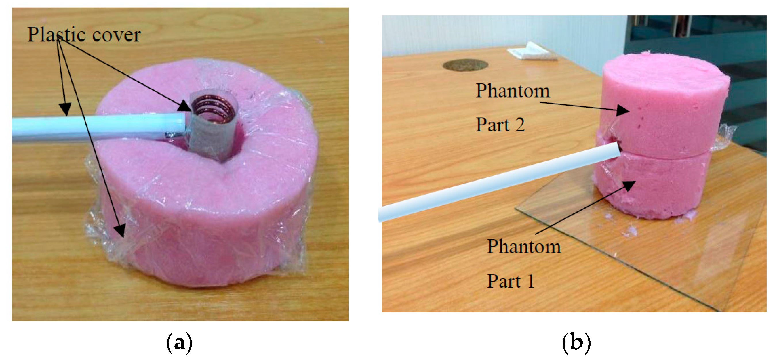
5.2. Phantom Fabrication and Measurement

In this paper, two human body phantoms that are equivalent to biological human stomach properties were fabricated. Each of the phantoms consists of two parts which represent the top and bottom part. The target was to fabricate two human stomach phantoms with different conductivity, which represent higher (σ = 1.1) and lower (σ = 0.6) conductivity characteristics.
The details of the chemical composition used to fabricate the human body phantoms are listed in Table 3. In order to fabricate the phantom at the desired permittivity and conductivity, a suitable quantity of chemicals is needed.
The fabricated phantoms are shown in Figure 15a,b whilst the measurement setup for the phantom dielectric permittivity and conductivity is shown in Figure 15c. From observation, the physical structure of Phantom 1 is solid and it is expected to have full stability for antenna measurement. On the other hand, for Phantom 2, the structure is a little bit sticky and watery due to the lesser amount of salt used in the fabrication.
For phantom measurement, 5 points are set on the surface of the phantoms in order to measure the dielectric permittivity and conductivity, as shown in Figure 15c. The phantom was measured using a dielectric probe. The measurement data consist of the real part of the data and the imaginary part as in Equation (13), which were then converted as in Equation (14) and Equation (15).
Here, εc is given by Equation (13):
ε c = ε r + j ε i
Moreover, εi is related to σ by the next expression:
ε i = σ ω ε o
Hence, σ can be calculated by the next equation by substituting ω = 2 π f and ε o = 10 9 36 π in Equation (14):
σ = ε i 45
By using the average values of the real part εr, the permittivity values for the fabricated phantoms are determined and the conductivity value can be calculated from Equation (15). The measured permittivity and conductivity values for the fabricated phantoms are Phantom 1 (εr = 63.5, σ = 1.04 S/m) and Phantom 2 (εr = 64.5, σ = 0.59 S/m), respectively. The graph of phantom measurement data is shown in Figure 16.

5.3. Antenna Measurement Setup

The antenna placement in a human body phantom is shown in Figure 17a, and the actual antenna measurement setup is shown in Figure 17b. Since an air gap must be ensured as no direct contact between the antenna and the human phantom is allowed, the antenna and the coaxial cable (balun) were carefully covered with plastic before placing the antenna in the middle of the human phantom. The metal isolation is important in order to ensure the accuracy of the measured results. Furthermore, as a small antenna is highly sensitive, in order to ensure the accuracy of the measurement data, the coaxial cable and antenna positions in the phantom were carefully adjusted during the measurement.

6. Measurement Results

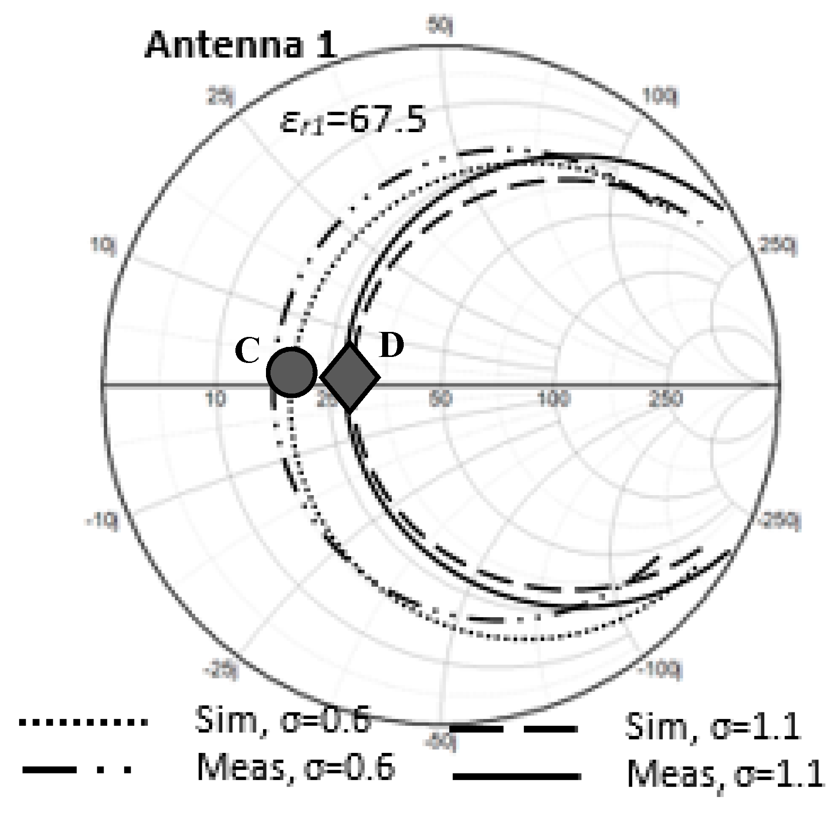
6.1. Input Resistance
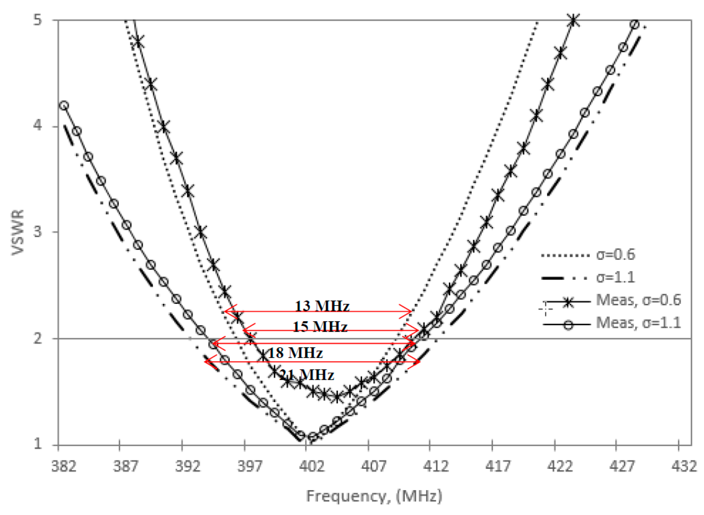
To confirm the simulated results for the input resistance at points C and D, measurements for antenna input resistance are needed. The fabricated NMHA was measured on Phantom 1 and Phantom 2. The simulated and measured antenna input resistance results for the fabricated NMHA in both Phantom 1 and Phantom 2 are shown in Figure 18.
Based on Figure 18, for Rin in Phantom 1, the simulated and measured Rin at point C are 20.62 Ω and 17.52 Ω, respectively, and the simulated and measured Rin for Phantom 2 at point D are and 29.02 Ω and 28.57 Ω, respectively. There is a slight difference of about 3 Ω between the simulated and measured Rin at point C. One of the reasons was due to the phantom’s physical structure, which was observed to be sticky and watery. This might affect the stability of the antenna setup in the phantom, because the antenna was expected to be kept still in the phantom during the antenna measurement. Thus, a slight movement of the antenna might cause the input resistance result to be shifted. Overall, it can be concluded that the simulated and measured results agreed rather well.

6.2. Bandwidth

The measured and simulation results of the antenna VSWR characteristics are shown in Figure 19. The simulated and measured results conform well to each other. At VSWR = 2, the simulated and measured bandwidths of the NMHA at point C (in phantom 2) are 15 MHz and 13 MHz, respectively, and correspond to a fractional bandwidth of approximately 3.73% and 3.23%, respectively. While at point D, σ = 1.1, the simulated and measured bandwidths are 21 MHz and 18 MHz with a FBW of 5.22% and 4.48%, respectively.

7. Discussion

The increase of input resistance (Rin) for the normal-mode helical antenna (NMHA) in human body conditions has been examined by electromagnetic simulations and experiments. The reason of the increase of Rin was found to be due to the decrease of current on the NMHA. As an effect of the rise in Rin values, the increment of bandwidth was also validated. The important data in this paper are listed as follows:
By electromagnetic simulations:
  • The relation between the increase of input resistance (Rin) and dielectric permittivity (εr) and conductivity (σ).
  • The relation between input resistance (Rin) and current distributions.
  • The relation between input resistance (Rin) and bandwidth (BW).
By experimental data with a fabricated body phantom:
  • Input resistance (Rin).
  • Bandwidth (BW).
For a future research direction, Rin measurements for different permittivities and conductivities such as εr = 11.6 and σ = 0.3 will be conducted. Moreover, the reason of the current decreasing by the increase of conductivity will be validated through an analytical approach for electromagnetic field and current relations.

Author Contributions

Conceptualization, N.Z. and Y.Y.; Data curation, N.Z.; Formal analysis, N.Z. and Y.Y.; Funding acquisition, T.A.L., N.K.A., Y.Y. and K.K.; Methodology, N.Z.; Project administration, T.A.L., N.K.A. and K.K.; Resources, T.A.L. and N.H.A.R.; Software, N.Z., K.K. and N.H.A.R.; Supervision, T.A.L., N.K.A. and K.K.; Validation, N.Z. and Y.Y.; Visualization, T.A.L.; Writing—original draft, N.Z.; Writing—review and editing, Y.Y. and N.H.A.R. All authors have read and agreed to the published version of the manuscript.

Funding

This research is funded by the Ministry of Higher Education, Malaysia (MoHE-MyPhD), University of Malaya grant (GPF015A-2019) and MJIIT Fundamental Research Grant Scheme (FRGS) vote number 5F046 and 5F063.

Acknowledgments

The authors would like to thank Tarmizi Ali of the ARG Laboratory, UiTM and Shah Alam for their help with phantom measurement, and also a special thanks to all the researchers of the Communication Systems and Networks Research Lab, Malaysia–Japan International Institute of Technology, Universiti Teknologi Malaysia, Kuala Lumpur, Malaysia for their support and help on this project.

Conflicts of Interest

The authors declare no conflict of interest.

References

  1. Singh, K. Biotelemetry: Could technological developments assist healthcare in rural india. Int. Electron. J. Rural Remote Heal. Res. Educ. Pract. Policy 2001, 3, 6. [Google Scholar]
  2. Tanaka, T.; Sonoda, K.; Okochi, S.; Chan, A.; Nii, M.; Kanda, K.; Fujita, T.; Higuchi, K.; Maenaka, K. Wearable Health Monitoring System and its Applications. In Proceedings of the Fourth International Conference on Emerging Trends in Engineering & Technology (ICETET), Port Louis, Mauritius, 18–20 November 2011; pp. 143–146. [Google Scholar]
  3. Loktongbam, P.; Pal, D.; Koley, C. Design of an implantable antenna for biotelemetry applications. J. Microsyst. Technol. 2019, 1–10. [Google Scholar] [CrossRef]
  4. Nguyen, T.H.; Nguyen, T.L.H.; Vuong, T.P.; Chan, A.; Nii, M. A Printed Wearable Dual Band Antenna for Remote Healthcare Monitoring Device. In Proceedings of the 2019 IEEE-RIVF International Conference on Computing and Communication Technologies (RIVF), Danang, Vietnam, 20–22 March 2019; pp. 1–5. [Google Scholar]
  5. Palandoken, M. Compact bioimplantable MICS and ISM band antenna design for wireless biotelemetry applications. Radioengineering 2017, 26, 917–918. [Google Scholar] [CrossRef]
  6. Pantelopoulos, A.; Bourbakis, N.G. A survey on wearable sensor-based systems for health monitoring and prognosis. IEEE Trans. Syst. Man Cybern. Part C Appl. Rev. 2010, 40, 1–12. [Google Scholar] [CrossRef] [Green Version]
  7. Long, V.S.; To, T.L.; Dung, T.H. Heart-Rate Monitoring Device based on Fluxgate Sensors. In Proceedings of the 2019 International Conference on System Science and Engineering (ICSSE), Dong Hoi, Vietnam, 20–21 July 2019; pp. 437–440. [Google Scholar]
  8. Sato, H.; Yoshimura, K.; Nakamoto, H.; Ishibashi, D.; Nakata, Y.; Yaginuma, Y.; Masui, S. 19.2 cm3 flexible fetal heart rate sensor for improved quality of pregnancy life. In Proceedings of the IEEE Biomedical Circuits and Systems Conference (BioCAS), Shanghai, China, 17–19 October 2016; pp. 140–143. [Google Scholar]
  9. Schires, E.; Georgiou, P.; Lande, T.S. Vital Sign Monitoring Through the Back Using an UWB Impulse Radar With Body Coupled Antennas. IEEE Trans. Biomed. Circuits Syst. 2018, 12, 292–302. [Google Scholar] [CrossRef]
  10. Kachuee, M.; Kiani, M.M.; Mohammaadzade, H.; Shabany, M. Cuffless Blood Pressure Estimation Algorithms for Continuous Health-Care Monitoring. IEEE Trans. Biomed. Eng. 2017, 64, 859–869. [Google Scholar] [CrossRef]
  11. Cong, P.; Ko, W.H.; Young, D.J. Wireless Batteryless Implantable Blood Pressure Monitoring Microsystem for Small Laboratory Animals. IEEE Sens. J. 2010, 10, 243–254. [Google Scholar] [CrossRef]
  12. Ullah, S.; Higgins, H.; Braem, B.; Latre, B.; Blondia, C.; Moerman, I.; Saleem, S.; Rahman, Z.; Kwak, K.S. A comprehensive survey of wireless body area networks on PHY, MAC, and network layers solutions. J. Med. Syst. 2012, 36, 1065–1094. [Google Scholar] [CrossRef] [Green Version]
  13. Presti, D.L.; Massaroni, C.; D’Abbracio, J.; Massari, L.; Caponero, M.; Longo, U.G.; Formica, D.; Oddo, C.M.; Schena, E. Wearable System Based on Flexible FBG for Repiratory and Cardiac Moniroring. IEEE Sens. J. 2019, 19, 7391–7398. [Google Scholar] [CrossRef]
  14. Ren, H.; Jin, H.; Chen, C.; Ghayvat, H.; Chen, W. A Novel cardiac Auscultation Monitoring System for Healthcare. IEEE J. Transl. Eng. Health Med. 2018, 6, 1–12. [Google Scholar] [CrossRef]
  15. Holmer, M.; Sandberg, F.; Solem, K.; Grigonytė, E.; Olde, B.; Sörnmo, L. Extracting a cardiac Signal From the Extracorporeal Pressure Sensors of a Hemodialysis Machine. IEEE Trans. Biomed. Eng. 2015, 62, 2343–2352. [Google Scholar] [CrossRef] [PubMed]
  16. Turicchia, L.; Valle, B.D.; Bohorquez, J.L.; Sanchez, W.R.; Misra, V.; Fay, L.; Tavakoli, M.; Sarpeshkar, R. Ultralow-Power Electronics for Cardiac-Monitoring. IEEE Trans. Circuits Syst. I Regul. Pap. 2010, 57, 2279–2290. [Google Scholar] [CrossRef]
  17. Nemati, E.; Deen, M.J.; Mondal, T. A wireless wearable ECG sensor for long-term applications. IEEE Commun. Mag. 2012, 50, 36–43. [Google Scholar] [CrossRef]
  18. Zainudin, N.; Abdul Latef, T.; Yamada, Y.; Kamardin, K.; Aridas, N.K.; Baharin, R.H.M. Measured Results of Input Resistance of NMHA in a Body Phantom. In Proceedings of the 2nd International Conference on Telematics and Future Generation Networks (TAFGEN 2018), Kuching, Malaysia, 24–26 July 2018; pp. 87–92. [Google Scholar]
  19. Baharin, R.H.M.; Uno, T.; Arima, T.; Zainudin, N.; Yamada, Y.; Kamardin, K.; Michishita, N. Effects of the permittivity and conductivity of human body for normal-mode helical antenna performance. IEICE Electron. Express 2019, 16, 1–6. [Google Scholar] [CrossRef] [Green Version]
  20. Liu, C.; Guo, Y.X.; Xiao, S. Circularly polarized helical antenna for ISM-band ingestible capsule endoscope systems. IEEE Trans. Antennas Propag. 2014, 62, 6027–6039. [Google Scholar] [CrossRef]
  21. Baharin, R.H.M.; Yamada, Y.; Kamardin, K.; Dinh, N.Q.; Michishita, N. Input resistances of small normal-mode helical antennas in dielectric materials. In Proceedings of the 2017 IEEE Asia Pacific Microwave Conference (APMC), Kuala Lumpar, Malaysia, 13–16 November 2017; pp. 1175–1178. [Google Scholar]
  22. Hatmi, F.E.L.; Grzeskowiak, M.; Alves, T.; Protat, S.; Picon, O. Magnetic loop antenna for wireless capsule endoscopy inside the human body operating at 315 MHz: Near field behavior. In Proceedings of the 2011 11th Mediterranean Microwave Symposium (MMS), Hammamet, Tunisia, 8–10 September 2011; pp. 81–87. [Google Scholar]
  23. Merli, F.; Bolomey, L.; Zurcher, J.-F.; Corradini, G.; Meurville, E.; Skrivervik, A.K. Design, realization and measurements of a miniature antenna for implantable wireless communication systems. IEEE Trans. Antennas Propag. 2011, 59, 3544–3555. [Google Scholar]
  24. Huang, B.; Yan, G.Z.; Zan, P. Design of ingested small microstrip antenna for radiotelemetry capsules. Electron. Lett. 2007, 43, 1178–1179. [Google Scholar] [CrossRef]
  25. Kwak, S.I.; Chang, K.; Yoon, Y.J. The helical antenna for the capsule endoscope. In Proceedings of the 2005 IEEE Antennas and Propagation Society International Symposium, Washington, DC, USA, 3–8 July 2005; pp. 804–807. [Google Scholar]
  26. Cheng, X.; Wu, J.; Blank, R.; Senior, D.E.; Yoon, Y.-K. An omnidirectional wrappable compact patch antenna for wireless endoscope applications. IEEE Antennas Wirel. Propag. Lett. 2012, 11, 1667–1670. [Google Scholar] [CrossRef]
  27. Das, R.; Yoo, H. A wideband circularly polarized conformal endoscopic antenna system for high-speed data transfer. IEEE Trans. Antennas Propag. 2017, 65, 2816–2826. [Google Scholar] [CrossRef]
  28. Wang, J.; Leach, M.; Lim, E.G.; Wang, Z.; Pei, R.; Huang, Y. An implantable and conformal antenna for wireless capsule endoscopy. IEEE Antennas Wirel. Propag. Lett. 2018, 17, 1153–1157. [Google Scholar] [CrossRef]
  29. Alrawashdeh, R.; Huang, Y.; Cao, P.; Lim, E. A new small conformal antenna for capsule endoscopy. In Proceedings of the 2013 7th European Conference on Antennas and Propagation (EuCAP), Gothenburg, Sweden, 8–12 April 2013; pp. 220–223. [Google Scholar]
  30. Houzen, T.; Takahashi, M.; Ito, K. Implanted Antenna for an Artificial Cardiac Pacemaker System. In Proceedings of the Progress in Electromagnetics Research Symposium, Prague, Czech Republic, 27–30 August 2007; pp. 51–54. [Google Scholar]
  31. Yun, S.; Kim, K.; Nam, S. Outer-Wall Loop Antenna for Ultrawideband Capsule Endoscope System. IEEE Antennas Wirel. Propag. Lett. 2010, 9, 1135–1138. [Google Scholar] [CrossRef]
  32. Lim, E.G.; Wang, Z.; Yu, F.Z.; Tillo, T.; Man, K.L.; Wang, J.C.; Zhang, M. Transmitter antennas for wireless capsule endoscopy. In Proceedings of the 2012 International SoC Design Conference (ISOCC), Jeju Island, South Korea, 4–7 November 2012; pp. 269–272. [Google Scholar]
  33. Lee, S.H.; Lee, J.; Yoon, Y.J.; Park, S.; Cheon, C.; Kim, K.; Nam, S. A Wideband Spiral Antenna for Ingestible Capsule Endoscope Systems: Experimental Results in a Human Phantom and a Pig. IEEE Trans. Biomed. Eng. 2011, 58, 1734–1741. [Google Scholar] [PubMed]
  34. Mohd Baharin, R.H.; Tuan, N.T.; Yamada, Y.; Kamardin, K. Electrical characteristic changes by setting conditions of Normal-Mode Helical Antenna in a phantom. In Proceedings of the 2016 IEEE Asia-Pacific Conference on Applied Electromagnetics (APACE), Langkawi, Malaysia, 11–13 December 2016; pp. 73–78. [Google Scholar]
  35. Liao, Y.; Zhang, Y.; Liang, Z.C.; Fang, J.P.; Gao, W. Effects of Dielectric Materials on Impedance Characteristics of Embedded Small Normal Mode Helical Antenna. Appl. Mech. Mater. 2014, 446, 1059–1063. [Google Scholar] [CrossRef]
  36. Tuan, N.T.; Dinh, N.Q.; Yamada, Y.; Mohd Baharin, R.H.; Kamardin, K.; Dung, D.T.; Michishita, N. Deterministic Equation of Self-Resonant Structures for Normal-Mode Helical Antennas Implanted in a Human Body. IEEE Antennas Wirel. Propag. Lett. 2018, 17, 1377–1381. [Google Scholar] [CrossRef]
  37. ERC RECOMMENDATION 70-03 (Tromsø 1997 and Subsequent Amendments). Available online: http://docplayer.net/5081624-Erc-recommendation-70-03-tromso-1997-and-subsequent-amendments-relating-to-the-use-of-short-range-devices-srd.html (accessed on 6 February 2020).
  38. Kim, J.; Rahmat-samii, Y. Implanted Antennas Inside a Human Body: Simulations, Designs, and Characterizations. IEEE Trans. Microw. Theory Tech. 2004, 52, 1934–1943. [Google Scholar] [CrossRef]
Figure 1. Integration of various sensors on a patient for remote health monitoring.
Sensors 20 00958 g001
Figure 2. Normal-mode helical antenna (NMHA) structure and electrical current model.
Sensors 20 00958 g002
Figure 3. NMHA simulation model. ([2018] IEEE. Reprinted, with permission, from [18]).
Sensors 20 00958 g003
Figure 4. NMHA self-resonant structure.
Sensors 20 00958 g004
Figure 5. Input impedance in a Smith chart plot for εr1 = 67.5 and σ = 0, 1.1.
Sensors 20 00958 g005
Figure 6. NMHA input resistance with respect to conductivity.
Sensors 20 00958 g006
Figure 7. Electric field distributions of NMHA in the human stomach, εr1 = 67.5. (a) σ = 0. (b) σ = 0.3. (c) σ = 1.1. (d) E-field legend scale.
Sensors 20 00958 g007
Figure 8. Current distribution of a NMHA wire for εr1 = 67.5, (σ = 0, 0.3, 0.6, 1.1).
Sensors 20 00958 g008
Figure 9. Current distribution for εr1 = 67.5, (σ = 0, 0.3, 0.6, 1.1).
Sensors 20 00958 g009
Figure 10. Calculated input resistance for εr1 = 67.5.
Sensors 20 00958 g010
Figure 11. Antenna bandwidth for εr1 = 67.5, σ = 0, 0.3, 0.6, 1.1.
Sensors 20 00958 g011
Figure 12. Relation of simulated Rin and fractional bandwidth (FBW) by conductivity for εr1 = 67.5.
Sensors 20 00958 g012
Figure 13. Simulated radiation pattern for εr1 = 67.5, σ = 0, σ = 1.1.
Sensors 20 00958 g013
Figure 14. Fabricated NMHA.
Sensors 20 00958 g014
Figure 15. Fabricated phantoms: (a) human stomach phantom for higher σ, (b) human stomach phantom for lower σ, (c) phantom measurement setup.
Sensors 20 00958 g015
Figure 16. Phantom measurement data for human stomach phantoms of higher and lower conductivity.
Sensors 20 00958 g016
Figure 17. Antenna measurement setup. (a) Antenna placement in a phantom; (b) actual measurement setup. ([2018] IEEE. Reprinted, with permission, from [18])
Sensors 20 00958 g017
Figure 18. Simulated and measured input resistance for Antenna 1 in a higher conductivity (σ = 1.1) and lower conductivity (σ = 0.6) human stomach phantom.
Sensors 20 00958 g018
Figure 19. Antenna bandwidth for εr1 = 67.5, σ = 0.6, 1.1.
Sensors 20 00958 g019
Table 1. Simulation parameters. MICS: medical implant communication service.
AspectParameter
SimulatorFEKO 2018Method of Moment
FrequencyMICS Band402 MHz
AntennaHeight, H/λg 0.2
Diameter, D/λg0.0965~0.1210
Number of turns, N7
Diameter of wire, d1.2 mm
Mesh size, Δlλg/100
Metallic Wire, Copper5.8 × 106 (S/m)
Dielectric (Human Body)Permittivity, εr 67.5, 46.7, 11.6
Permeability, μr1
Conductivity, σ0~1.1
Wavelength material, λg90.77 mm,
Mesh size, Δmλg/100
Table 2. Calculation of efficiency, ηa.
εr1 = 67.5Ra [Ω]Rin(σ) [Ω]ηa [dBi]GA (sim) [dBi]
σ = 0 [S/m]0.2270.8−5.47−5.357
σ = 1.1 [S/m]0.21729.02−21.26−21.78
Table 3. Chemical composition for human body phantom fabrication.
Human Stomach Phantom
MaterialsFunctionPhantom 1
εr1 = 67.5, σ = 1.1
Phantom 2
εr1 = 67.5, σ = 0.6
Distilled waterMain material400 mL400 mL
Polyethylene powderPermittivity6 g6 g
AgarForming material17.5 g17.5 g
Sodium Chloride (NaCl)Conductivity1.925 g0.9 g
XanthanThickener15 g15 g
Sodium Dehydro-acetatPreservative0.25 g0.25 g

