Article

X-Band Radar Cross-Section of Tandem Helicopter Based on Dynamic Analysis Approach

School of Aeronautic Science and Engineering, Beihang University, Beijing 100191, China
*
Author to whom correspondence should be addressed.
Sensors 2021, 21(1), 271; https://doi.org/10.3390/s21010271
Submission received: 25 November 2020 / Revised: 31 December 2020 / Accepted: 2 January 2021 / Published: 3 January 2021
(This article belongs to the Section Remote Sensors)

Abstract

:
In order to study the radar signature of a tandem helicopter in the X-band, a dynamic analysis approach (DAA) is presented to determine its radar cross-section (RCS) under different influence factors. The basic passage time, rotation speed, observation angle, rotor disk inclination, fuselage attitude angle and Doppler feature are studied and discussed in detail. The results show that the dynamic characteristics of the rotor RCS will bring significant changes to the peak and average values of the helicopter RCS. Within a given observation angle range, a larger elevation angle is undesirable for helicopter stealth. The inclination of the rotor disc will affect the many small peaks and local fluctuations of the helicopter RCS. The positively increased attitude angle will have an undesirable effect on the average RCS and dynamic characteristics of the helicopter. The DAA is feasible and effective for studying the radar cross-section of a tandem helicopter.

1. Introduction

As a uniquely configured aircraft, the tandem helicopter has the advantages of heavy load, small space size and high hovering efficiency, which makes it widely used in transportation, passenger transportation and rescue tasks. Hence, studying the electromagnetic scattering characteristics of tandem helicopters has important academic significance and engineering value [1,2,3].
For the solution of the radar cross-section (RCS) of aircraft targets, many research methods and work have been presented, including the method of moment (MOM) [1], physical optics (PO) [4,5], flight testing [6,7] and physical theory of diffraction (PTD) [8]. The combination of the fact-based asymptotic method and the geometrical optics (GO) and PO hybrid method is used to calculate the RCS of a large target [9]. The quasi-static principle (QSP) is used to simulate the motion of the blade, and the RCS of the rotor is obtained by adopting PO and equivalent currents method [10]. Different from a single rotor structure, a tandem helicopter usually uses a dual rotor configuration, which brings a new source of scattering to the aircraft [11,12,13]. It can be seen that these existing RCS calculation methods can solve the electromagnetic scattering characteristics of the static and a small amount of quasi-static rotors. This obviously cannot satisfy the determination of the radar characteristics of the two large main rotors of the tandem helicopter [14].
In order to analyze the dynamic RCS response of a compound helicopter, a multi-rotor, dynamic scattering calculation method is presented [15]. This processing approach can bring support and reference for the solution of the radar characteristics of the tandem helicopter [16,17]. A dynamic transformation method based on PO and PTD was established to calculate the electromagnetic scattering characteristics of coaxial helicopters [18]. When controlling the flight attitude, the tilt angle of the rotor disc will also change the RCS of the helicopter [15,19,20]. The difference in structure from conventional unmanned helicopters is that unmanned tandem helicopters have no slender tail boom, with two rotors of the same size arranged in the longitudinal direction, one in the front and one in the back, and the rotors have the same rotation speed and opposite rotation directions [21,22,23]. In order to ensure the accuracy of simultaneous localization and mapping (SLAM) in the millimeter-wave band [24,25], a millimeter-wave radar SLAM assisted by the RCS feature of the target and inertial measurement unit is presented. With the extensive equipment of dual-band radars on various weapon platforms, the study of the electromagnetic scattering characteristics of helicopters in the X-band has also become important.
Previous studies on helicopter radar cross-sections were mostly static electromagnetic scattering calculations. In the past two years, dynamic RCS response analysis of rotor, coaxial helicopter and the compound helicopter has gradually appeared. Unlike the conventional layout of a helicopter, the tandem helicopter has two large main rotors, which are installed on the lower tower at the nose and the higher tower at the tail, noting that this design allows the two main rotors to affect the aircraft’s RCS within the circumferential azimuth range. According to the core idea of the dynamic scattering method [3], we apply this approach to the tandem helicopter and expand the independent calculation of the influence of the rotor disk tilt and the analysis of the Doppler characteristics. Therefore, this paper attempts to present a dynamic analysis approach (DAA) to determine the RCS of a tandem helicopter. In view of the uniqueness of this aircraft, important influencing factors will be analyzed and discussed, including rotation speed, observation direction, rotor disc inclination and attitude angle. It can be seen that the research on the RCS of the tandem helicopter has important engineering application value and academic significance for the stealth design of the helicopter.
In this article, the DAA is presented in Section 2. Models of helicopter and rotor are given in Section 3. The results of dynamic electromagnetic scattering are discussed in Section 4. Finally, the full text is summarized.

2. Dynamic Analysis Approach

The schematic of dynamic scattering of a tandem helicopter is shown in Figure 1, where Ab represents the angle between adjacent blades of the rotor, and the subscript numbers (1 and 2) refer to the serial number of the corresponding rotor, Ar is the rotation angle of the rotor, α is the azimuth of the radar station, β is the elevation angle, Vtip is the velocity of the blade tip, θ is the pitch angle of the helicopter, γ is the roll angle of the helicopter, Adf is the forward tilt angle of the rotor disc, Adr is the right tilt angle of the rotor disc. When the inclination angle of the rotor disc is equal to 0, the rotation axes of the two rotors are parallel to the z-axis.

2.1. Dynamic Process Simulation

The helicopter consists of two main rotors and a fuselage; thus, its initial model can be expressed as follows:
m h ( t =   0 ) = { m r 1 ( t =   0 ) , m r 2 ( t =   0 ) , m f ( t =   0 ) }
where t is time, mh is the model of the tandem helicopter, mr1 is the model of rotor 1, mr2 is the model of rotor 2, mf is the model of the fuselage [3,15]. In the current coordinate system, when rotor 1 rotates, its dynamic model can be updated to:
M r 1 x ( m r 1 ( t = 0 ) ) = M r 1 ( x ( m r 1 ( t = 0 ) ) X r 1 ) | γ = θ = 0 , A df = A dr = 0
M r 1 x z ( m r 1 ( t ) ) = [ cos A r 1 ( t ) sin A r 1 ( t ) 0 sin A r 1 ( t ) cos A r 1 ( t ) 0 0 0 1 ] M r 1 x ( m r 1 ( t = 0 ) ) | γ = θ = 0 A df = A dr = 0
where Mr1 is the grid coordinate matrix of rotor 1, superscript x represents the translation along the x-axis, superscript xz represents the rotation around the z-axis in the current operation, Xr1 is the distance between the axis of rotor 1 and the z-axis in the initial state. When the rotor disc is tilted forward, the dynamic model of rotor 1 can be updated to:
M r 1 y ( m r 1 ( t ) ) = [ cos A df ( t ) 0 sin A df ( t ) 0 1 0 sin A df ( t ) 0 cos A df ( t ) ] M r 1 x z ( m r 1 ( t = 0 ) ) | A dr = 0 γ = θ = 0
where the superscript y represents the rotation around the y-axis. When the paddle is tilted to the right, the dynamic model of rotor 1 can be expressed as:
M r 1 x y ( m r 1 ( t ) ) = [ 1 0 0 0 cos A dr ( t ) sin A dr ( t ) 0 sin A dr ( t ) cos A dr ( t ) ] M r 1 y ( m r 1 ( t = 0 ) ) | γ = θ = 0
where the superscript xy represents the rotation around the x-axis in the current operation. For the rotational movement of rotor 2, there are the following descriptions:
M r 2 x ( m r 2 ( t = 0 ) ) = M r 2 ( x ( m r 2 ( t = 0 ) ) + X r 2 ) | γ = θ = 0 , A df = A dr = 0
M r 2 x z ( m r 2 ( t ) ) = [ cos A r 2 ( t ) sin A r 2 ( t ) 0 sin A r 2 ( t ) cos A r 2 ( t ) 0 0 0 1 ] M r 2 x ( m r 2 ( t = 0 ) ) | γ = θ = 0 A df = A dr = 0
where Mr2 is the grid coordinate matrix of rotor 2, superscript x represents the translation along the x-axis, superscript xz represents the rotation around the z-axis in the current operation, Xr2 is the distance between the axis of rotor 2 and the z-axis in the initial state, noting that the update of the rotor 2 model caused by the disc tilt is similar to the operation of rotor 1. Return the rotor model matrix obtained above to their initial position, and merge with the model of the fuselage, the dynamic model of the helicopter can be obtained as:
M h ( m h ( t ) ) = [ M r 1 z ( m r 1 ( t ) ) , M r 2 z ( m r 2 ( t ) ) , M f ( m f ( t =   0 ) ) ] | γ = θ = 0
where the superscript z represents the transformation about the z-axis. When the attitude angle of the fuselage changes, the helicopter model can be updated as follows:
M h x ( m h ( t ) ) = [ 1 0 0 0 cos γ sin γ 0 sin γ cos γ ] M h ( m h ( t ) ) | θ = 0
M h y ( m h ( t ) ) = [ cos θ 0 sin θ 0 1 0 sin θ 0 cos θ ] M h x ( m h ( t ) )
where superscript x represents the rotation around the x-axis in the current operation, superscript y represents the rotation around the y-axis in the current operation. When incident radar waves illuminate the helicopter, the illuminated area on its surface can be extracted as:
S ( t ) M h y ( m h ( t ) )
where S(t) is the illuminated area of the helicopter.

2.2. Electromagnetic Scattering Calculation

In the PO method, the far-field electric field formula can be expressed as follows:
E s ( m h ( t ) ) = e j k r 4 π r ( j ω μ ) S ( t ) J s e j k s r ( t ) d S + j k s 1 ε S ( t ) ρ s e j k s r ( t ) d S
where k is the wavenumber, ω is the angular frequency, μ is the magnetic permeability, Js is the surface current, s means radiation direction, r′ is the source point coordinate vector, r is the field point, ε is the dielectric constant, ρs is the charge density, dS is the integral facet [8,18]. Under the irradiation of plane waves, the target RCS calculation formula can be written as:
σ F ( t ) = lim R 4 π R 2 e s E s ( m h ( t ) ) | E i |
where R is the distance between the field point and the source point, es is the direction of the scattered electric field, Ei is the electric field intensity at the point of incidence.
For the far-field, the RCS formula can be further transformed into:
σ F ( t ) = 4 π R 2 1 | E i | ( j ω μ e j k r 4 π r S ( t ) e s J s e j k s r ( t ) d S )
Note that the surface current could be expressed as:
J s = 2 n   × H i
where n is the normal vector outside the surface element, Hi is the magnetic field intensity of the incident point. Considering the relationship between electric field and magnetic field, the calculation formula of RCS can be obtained as:
σ F ( t ) = j k π n ( e s × h i ) e j k w r 0 ( t ) I ( t )
w = s i
where hi is the direction of the incident magnetic field, r0 represents the coordinate vector of the reference point on the integral surface element, i is the unit vector of the incident wave, I(t) is an integral expression, which can be obtained according to the following calculation when triangular facets are used:
I ( t ) = { e j k w r m ( t ) j k | p | 2 m = 1 3 p L m s i n c ( k w L m 2 ) , | p | 0 A f , | p | = 0
sinc ( x ) = sin x / x
where Lm is the vector of the m-th edge on the facet, Af is the area of the integral facet; for more details, please refer to the literature [5,26], noting that p is a defined vector cross product:
p = n × w
PTD is used to solve the edge diffraction contribution of the target; for more information about PTD, please refer to the literature [5,8]. Therefore, the total RCS can be written as:
σ ( t ) = | i = 1 N F ( t ) ( σ F ( t ) ) i + j = 1 N E ( t ) ( σ E ( t ) ) j | 2 , t [ 0 , T obs ]
where σ is the radar cross-section, subscript E represents the edge contribution, and F represents the facet contribution. NE is the number of edges, NF is the number of facets, and Tobs is the recommended length of time for observation:
T obs max { t b , r 1 , t b , r 2 } | A df = A dr = 0 , γ = θ = 0
t b = A b ω r π 180 , A b = 360 N b
where tb is basic passage time, equal to the time it takes for the blade to rotate through the angle between two adjacent blades, Nb is the number of blades of the rotor, ωr is the angular velocity of the rotor.
T obs max { t b , max , N b , r 1 t b , r 1 , N b , r 2 t b , r 2 } | p a { A df , A dr , γ , θ } , p a 0
t b , max = max { t b , r 1 , t b , r 2 }
where pa is a custom angle parameter. The existence of Tobs can better present the complete dynamic characteristics of the RCS of the rotor or helicopter.

2.3. Doppler Analysis

Translate the current coordinate system to the center of rotor 1, the distance between any point P on the rotor surface and the radar can be expressed as:
R P ( t ) = ( R 0 ) 2 + ( l P ( x , y ) ) 2 + 2 l P ( x , y ) R 0 cos β 0 cos ( ω r 1 t + φ 0 + φ ( x , y ) )
where R0 is the distance between the radar and the rotation center of the rotor, lP is the distance from point P to the center of the rotor, β0 is the elevation angle of the radar beam, φ is the rotor phase, subscript 0 represents the initial phase:
l P ( x , y ) = x 2 + y 2
φ ( x , y ) = arctan y x
β 0 = A df + β
where Adr = 0. The angle between the radar line of sight and the vertical direction of point P at any time can be calculated as:
θ = arccos R 0 sin β 0 R P ( t )
When the main body of the rotor translates along the x-direction at speed Vm, the laser echo at point P can be expressed as:
S P ( t ) = exp { j 4 π cos β 0 λ [ l P cos ( ω r 1 t + φ 0 ) + V m t ] }
where λ is the wavelength. Then the micro-Doppler frequency at point P is:
f M D = 2 V m cos β 0 λ + 4 π n r 1 l P λ sin ( 2 π n r 1 t + φ 0 )
where nr1 is the rotating speed of rotor 1. The Doppler frequency of the blade tip is usually the most obvious; thus, it can be extracted as:
F dt = f M D | max ( l P ( x , y ) )
Regardless of translational motion, it can be seen from the literature [10] that the maximum Doppler frequency caused by the rotation of the rotor can be obtained when electromagnetic waves are incident parallel to the plane of the rotor disk:
f dmax = 2 f ω r 1 R r 1 c
where f represents the frequency of the radar wave, ωr1 represents the angular velocity of rotor 1, Rr1 is the radius of rotor 1. The normalized processing of the rotor radar cross-section can be expressed as:
σ n ( t ) = σ ( t ) max ( σ ( t ) ) min ( σ ( t ) )
In fact, fdmax is slightly smaller than the maximum of Fdt because the real rotor has a width, that is, the chord length, which leads to the maximum Doppler frequency appearing at the tip of the leading or trailing edge of the rotor.

2.4. Method Verification

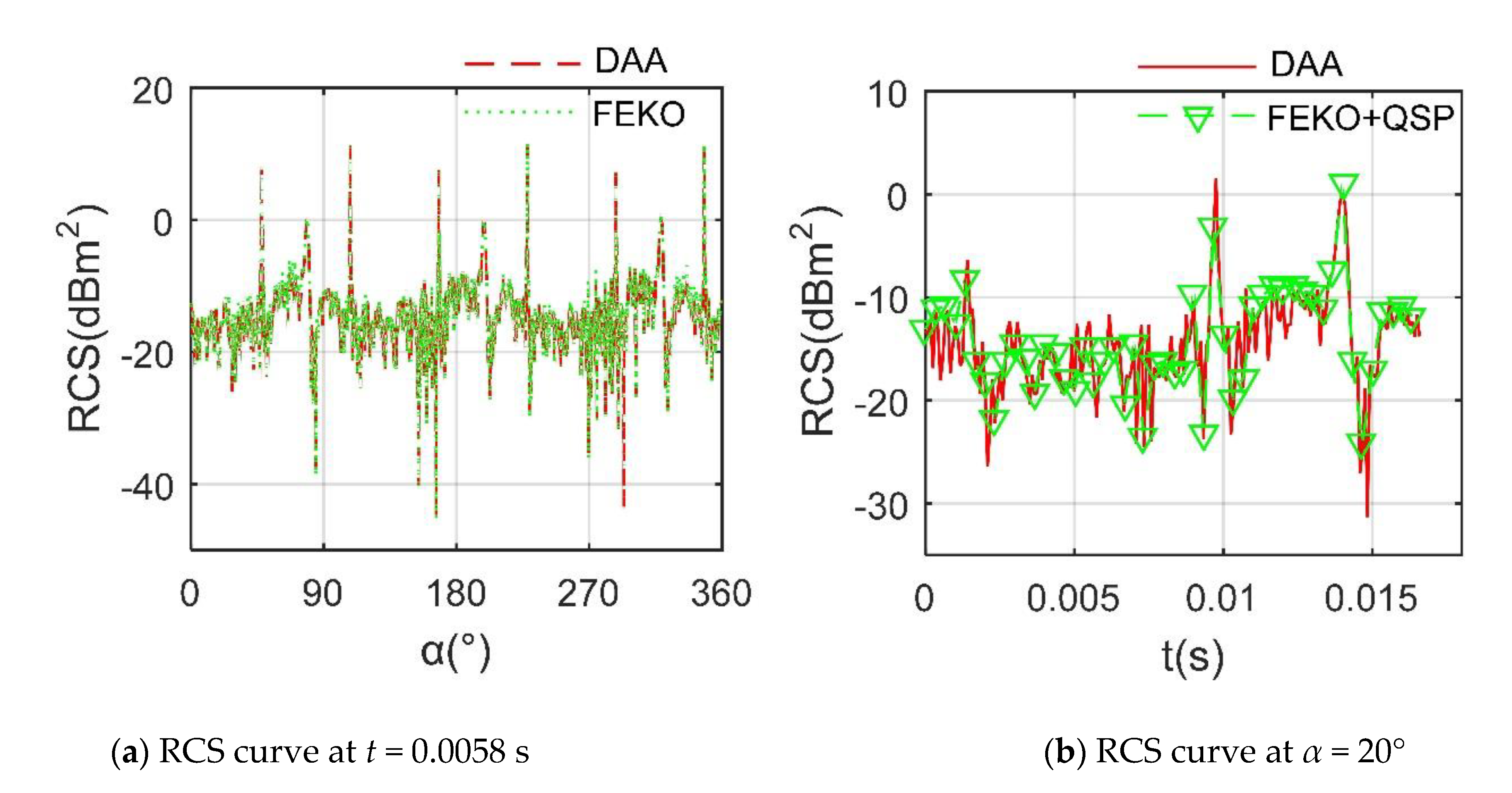
The validation of DAA is presented in Figure 2, where fRH refers to radar wave frequency and horizontal polarization, rotating speed of rotor 1 nr1 = 1200 r/min. The PO + method of the moment (MOM)/multilevel fast multipole method (MLFMM) in FEKO is used to calculate the RCS of the target and compare it with the result of DAA [3]. For the case of t = 0.0058 s, it can be seen that the two RCS curves are generally similar, including peak size, peak position and overall trend. In the range of 56.5°~72.75° and 325.3°~347° azimuth angles, the calculation result of FEKO is slightly higher than that of DAA, where the RCS means of the former is −9.36 dBm2, while that of the latter is −9.61 dBm2. These results show that DAA is accurate to calculate the transient or static RCS of the target.
For the RCS curve at α = 20°, the quasi-static principle (QSP) is used to discretize the rotational motion of the rotor so that the conventional method can proceed to the calculation of rotor dynamic RCS. It can be seen that the RCS curve determined by DAA can help better pass through the discrete data points calculated by FEKO, but DAA clearly reflects the subtle changes in rotor RCS over time, where the RCS means of the DAA curve is −11.45 dBm2, and that of the other set of data is −10.72 dBm2. These results show that DAA is feasible and accurate to analyze the dynamic RCS of the target.

3. Model of Tandem Helicopter

With reference to the outline layout of the CH-46 Sea Knight helicopter and the advanced design of the RAH-66 Comanche helicopter [5,8], the model of the tandem helicopter is established as shown in Figure 3, where Lfus, Wfus and Hfus are the lengths, width and height of the helicopter fuselage, respectively. Lfn is the distance from the vertex of the nose to the yz plane. Rr1 and Rr2 are the radius of rotor 1 and 2, respectively. When the rotor is not tilted, the rotor axis is parallel to the z-axis, and Xri (i = 1 or 2) is the distance from the axis of rotor i to the z-axis. Ht1 and Ht2 are the height of the rotor 1 tower and rotor 2 towers, respectively, where the sizes of these dimensions are presented in Table 1.
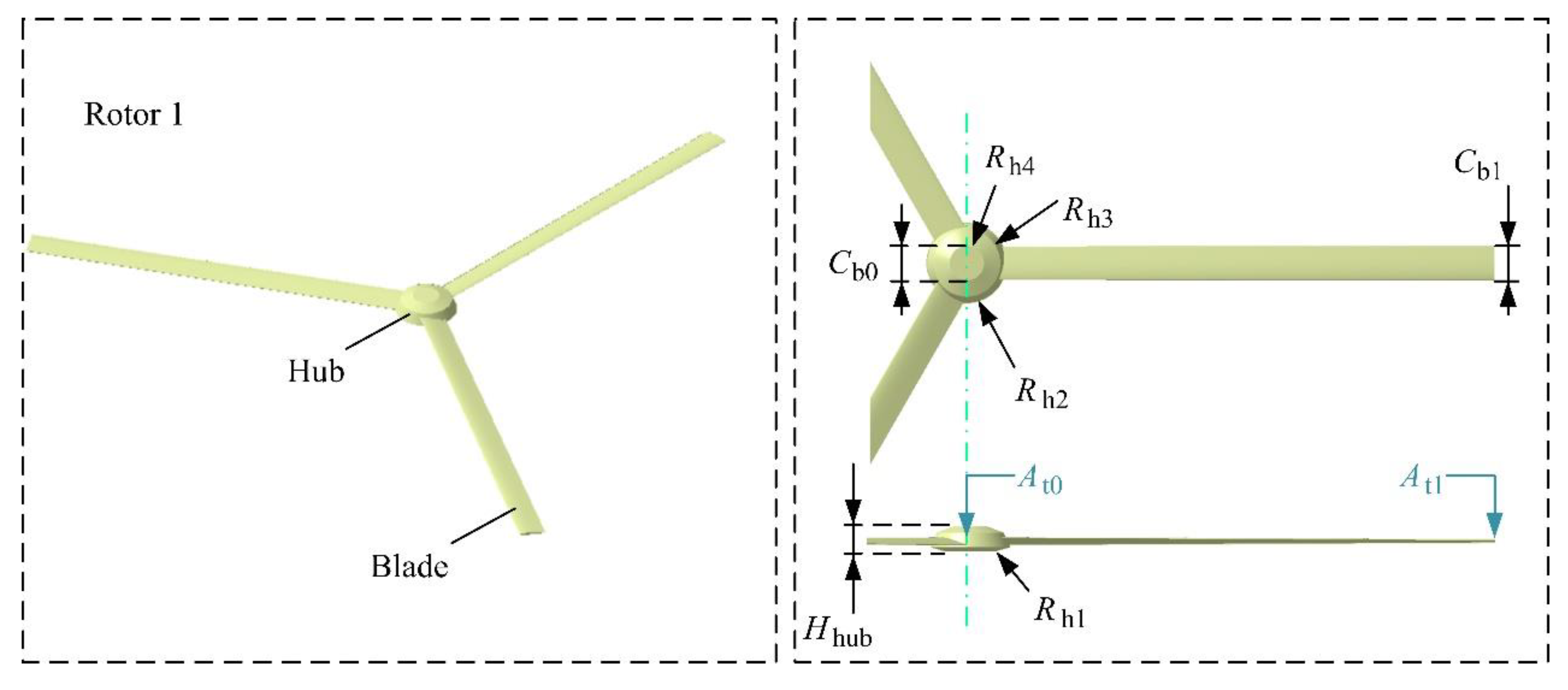
The model of rotor 1 is shown in Figure 4, where Cb0 and Cb1 represent the chord length at the root and the tip of the blade, respectively. Hhub is the height of the rotor hub, and its value is given in Table 2. At0 and At1, respectively, represent the torsion angle of the root and the tip of the blade. Rh1~Rh4 are the radius of each circular edge of the hub from bottom to top in turn. The model of Rotor 2 is the same in size as Rotor 1, and it can be regarded as the result of the symmetry of Rotor 1 about the yz plane and then translation.
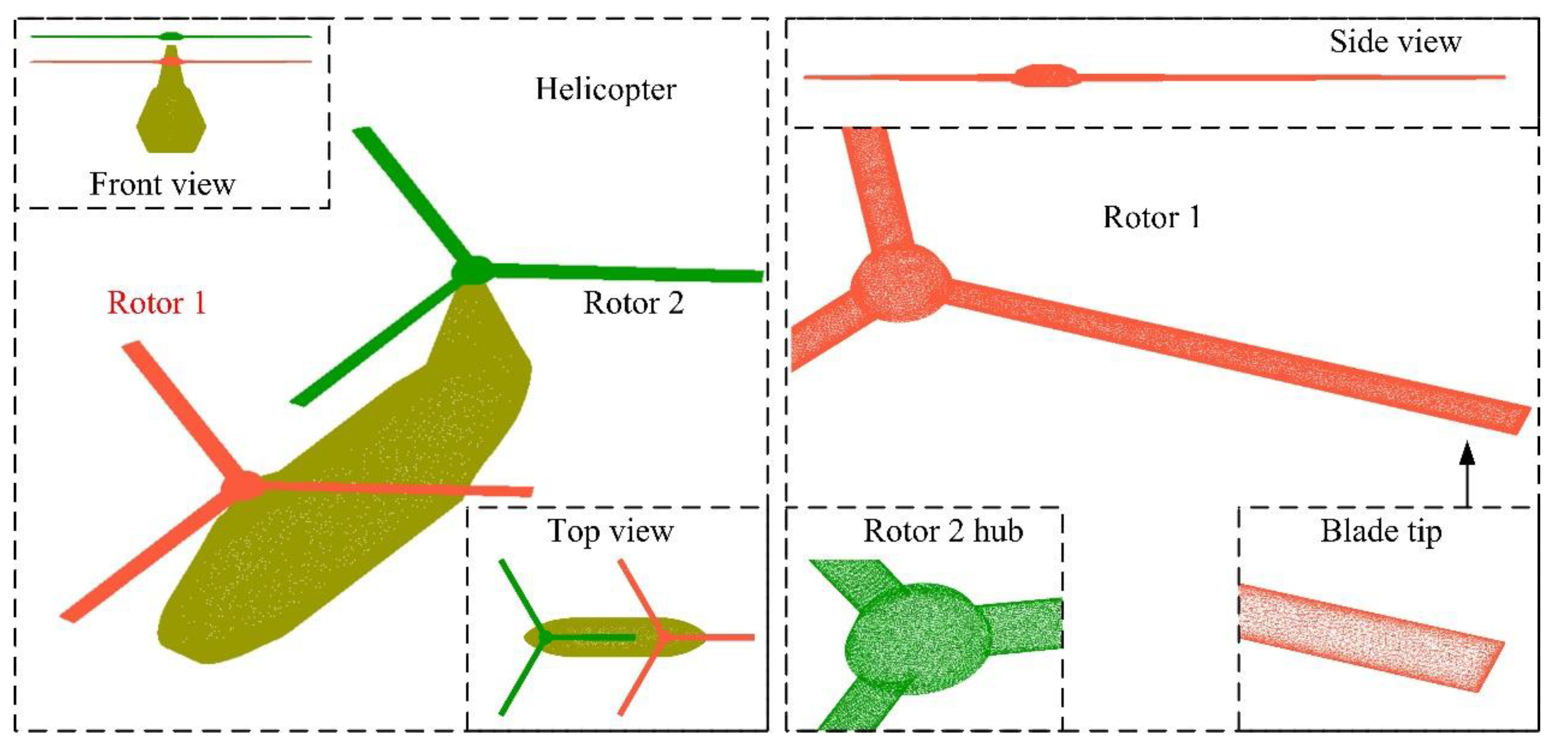
High-precision unstructured grid technology is used to divide the surface of the helicopter model, as shown in Figure 5, where dense mesh processing is used to handle edges and surfaces with large curvature changes. For the rotor, the leading edge, trailing edge, blade tip and hub edge have smaller dimensions and obvious split angle. For the surface of the helicopter fuselage, the geometrical dimensions of the sidelines, the nose, the top of the rotor tower and the edge of the tail are small.

4. Results and Discussion

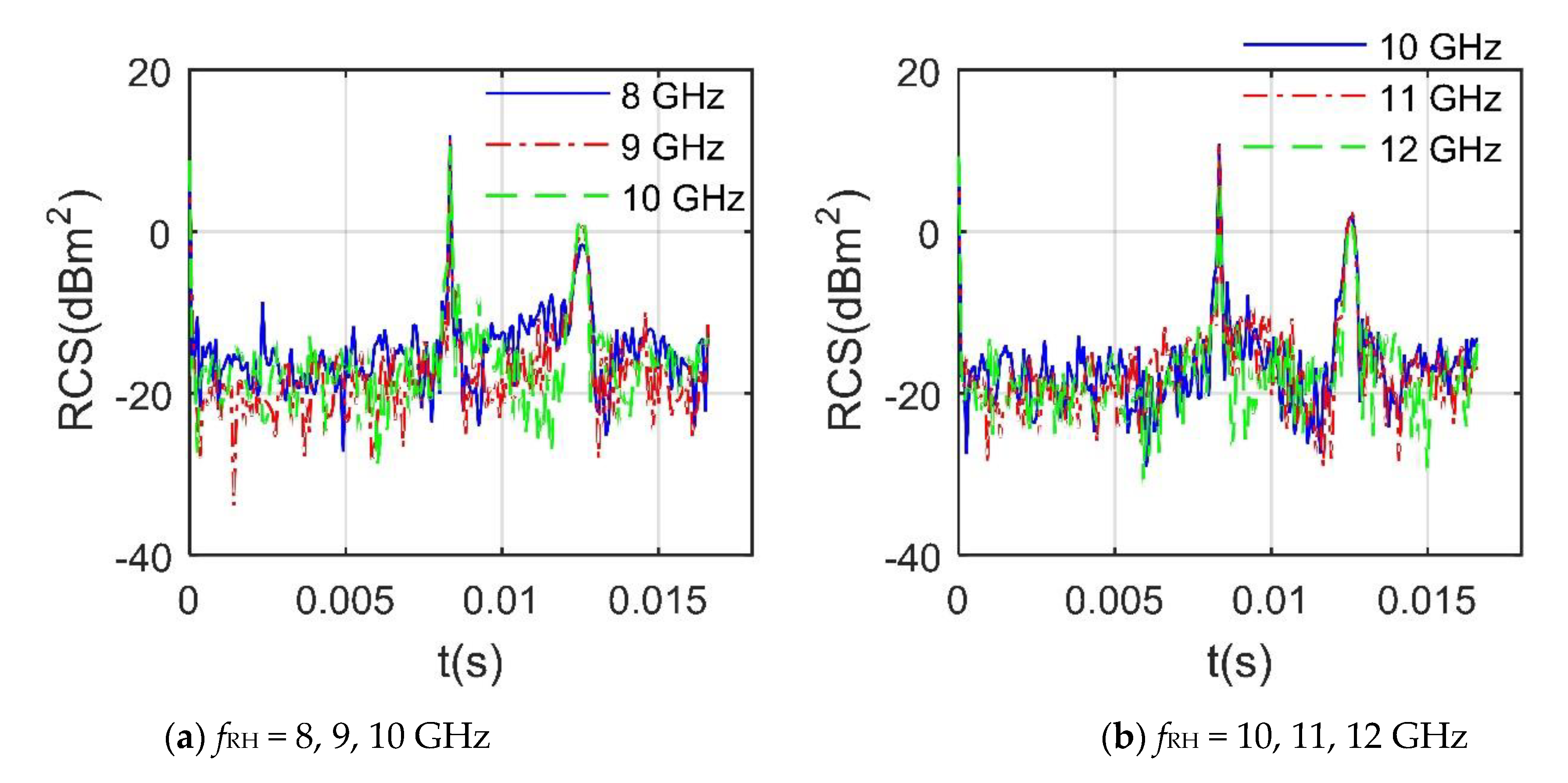
Figure 6 presents that the RCS curves of the rotor under various fRH in the X-band are obviously different, including fluctuation range, peak size and curve shape, while their peak positions are relatively consistent. The 5 RCS curves have peaks exceeding −1.651 dBm2 at t = 0, 8.33 × 10⁻³, and 1.26 × 10⁻² s. For the first RCS peak, the trailing edge of a blade is perpendicular to the incident radar wave, which makes a large number of strong scattering sources appear on the surface near the trailing edge. At t = 8.33 × 10⁻³ s, the peak at 8 GHz is 11.88 dBm2, while that at 12 GHz is 9.763 dBm2, because the rotor rotates 60°, making the leading edge of a blade perpendicular to the radar wave, which contributes to a significant increase in RCS. The RCS means of rotor 1 at different fRH is shown in Table 3, where the maximum difference between these means reached 0.952 dBm2. In order to capture the radar characteristics of the tandem helicopter, DAA is used to analyze its dynamic RCS under more influential factors in the following content.

4.1. Influence of Individual Rotor

Figure 7 provides that the RCS of rotor 1 under a given azimuth angle shows obvious periodic characteristics, where the inclination of the rotor disk and the attitude angle of the fuselage are both equal to 0. The minimum period of the dynamic RCS of the rotor at this time is equal to 0.0165 s, which is exactly equal to the basic passage time, where Nobs is a multiple of the basic passage time. Although the RCS curves under these 2 azimuths have many differences, including peak, fluctuation range and shape, their minimum periods are the same, where the peak of the RCS curve with α = 10° is 1.538 dBm2, and that at α = 20° is 2.009 dBm2, because for a single rotor with a fixed attitude, different observation angles determine the starting point of the rotor dynamic RCS, and the continuous rotation of the rotor will cause its blades to enter the next similar process after the basic passage time. This shows that DAA can well capture the periodic characteristics of the rotor RCS.
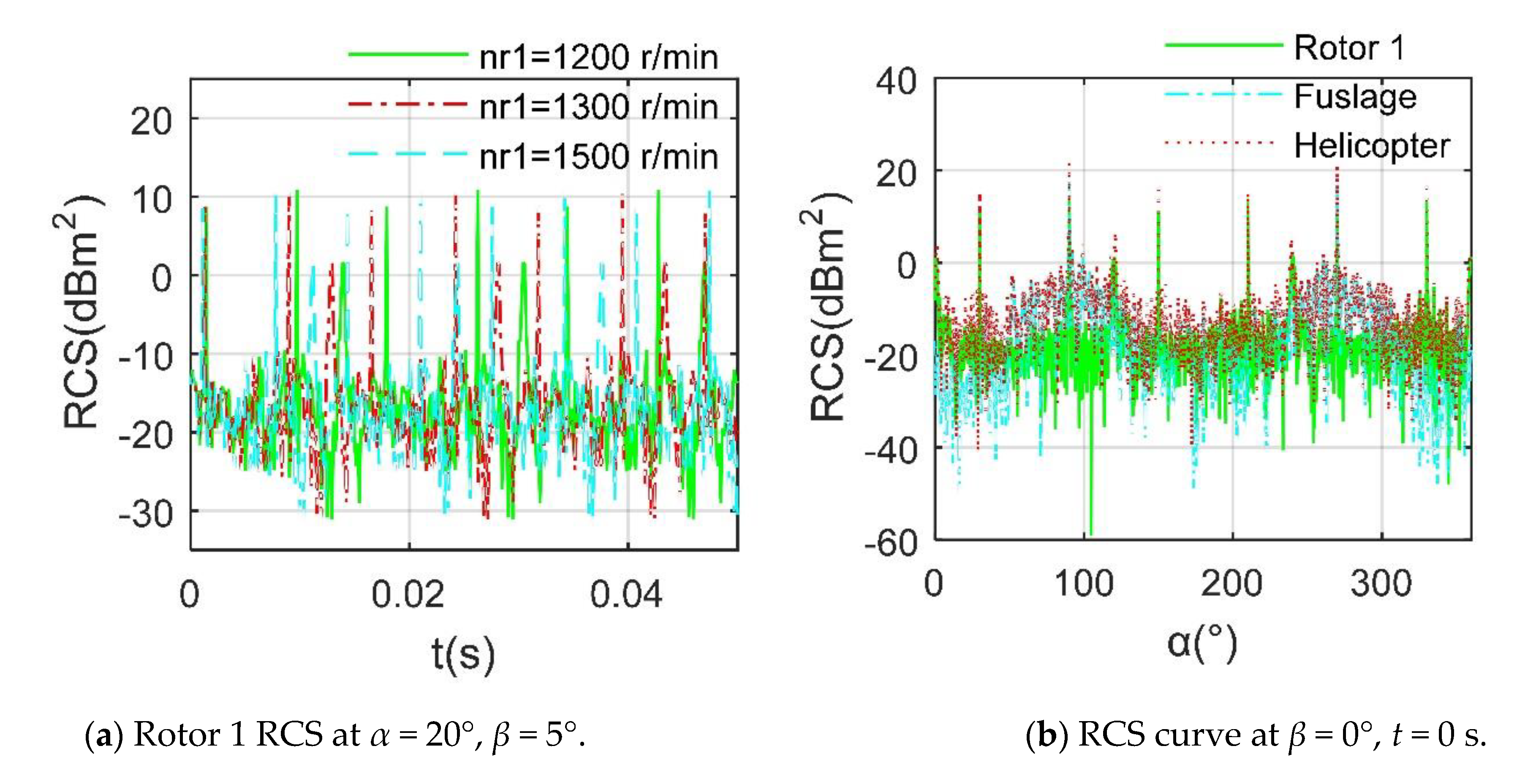
Figure 8 indicates that as the rotation speed increases, the RCS period of the rotor is obviously shortened. When nr1 = 1300 r/min, the dynamic RCS period of rotor 1 is equal to 0.0153 s, while this value is only 0.0132 s at 1500 r/min because the greater rotation speed allows any blade of the rotor to quickly complete the movement within the basic passage time. For the RCS results compared to fuselage and helicopter, it can be observed that the overall RCS level of the rotor is the lowest among the three, where the RCS means of the rotor is equal to −9.0752 dBm2, that of the fuselage is −7.3684 dBm2, and that of the helicopter is −3.0947 dBm2 because the overall configuration of the rotor is very thin, its projection in the radar incident direction is much smaller than that of the fuselage and helicopter. In addition, despite the huge size of the fuselage, it uses a better shape design, including inclined side panels, flat nose and sharp rotor tower. The rotor has a similar RCS order of magnitude compared with the fuselage and contributes a lot to the main peak of the helicopter, while the influence of rotation speed on rotor RCS is mainly reflected in the period.

4.2. Influence of Observation Angle

Figure 9 reveals that at a given β, the influence of the azimuth on the dynamic RCS of rotor 1 is mainly reflected in the initial RCS, where the inclination angle of the rotor disc and the attitude angle of the fuselage are both equal to 0. The RCS of the rotor at different azimuth angles has great similarities in other aspects, including peak size, curve shape and variation range. It can be found that the maximum peak of these RCS curves is equal to 10.86 dBm2, and the second-largest peak is 8.754 dBm2. The different starting points of these RCS curves are mainly due to the difference in the angle between the rotor and the incident radar wave at the initial moment, resulting in a difference in the comprehensive effect of the blade on the deflection of the radar wave. The similarity of these RCS curves is mainly because the rotor is in a horizontal position, and the elevation angle is small. In addition to the initial design of the propeller hub, these together lead to the similarity of the dynamic RCS of the rotor at different azimuths. These results indicate that the influence of the azimuth angle on the dynamic RCS of the horizontally placed rotor is mainly reflected in the initial RCS.
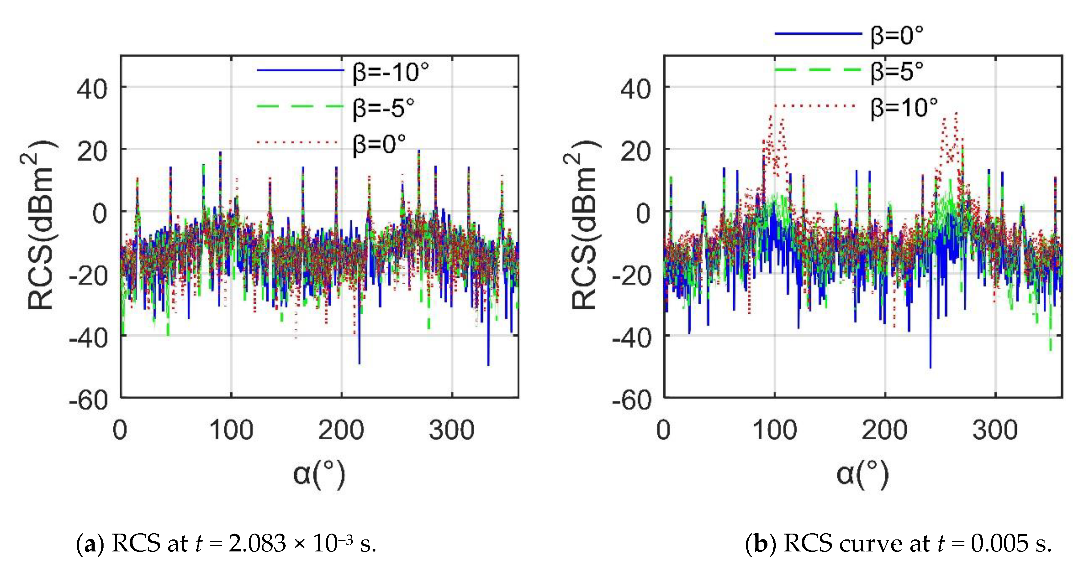
Figure 10 manifests that a positive β has a significant impact on the helicopter’s RCS~α at a given moment. For t = 2.083 × 10⁻³ s, the performance of the RCS curves is very similar, including peaks, curve trends and fluctuations, where the average value of the RCS curve at β =–10° is −3.8226 dBm2, that at β = −5° is −3.5141 dBm2, and that at β = 0° is −3.5755 dBm2. At this time, as β decreases from 0, the strong scattering source of the helicopter is mainly concentrated on the curved surface at the bottom of the fuselage; thus, these three RCS curves are relatively close. For t = 0.005 s, the three RCS curves are quite different, including peak size, fluctuation range, peak position and curve shape, where the peak of the curve at β = 0° is 18.5 dBm2 at α = 270°, that at β = 5° is 21.14 dBm2 at α = 270°, and that at β = 10° is 31.95 dBm2 at α = 264°. In addition, the average of the RCS curve at β = 0° is −3.6538 dBm2, and the peak value of the RCS curve at β = 10° is 14.4624 dBm2. The reason for the significant increase in RCS here is that the surface of the nose, the sides of the fuselage, the rotor towers, the front and rear edges of the blades, and the tip of the blade have become new scattering sources. These results indicate that although this helicopter uses a preliminary tilt design, it still has unfavorable RCS performance at a larger elevation angle.

4.3. Influence of Rotor Disk Inclination

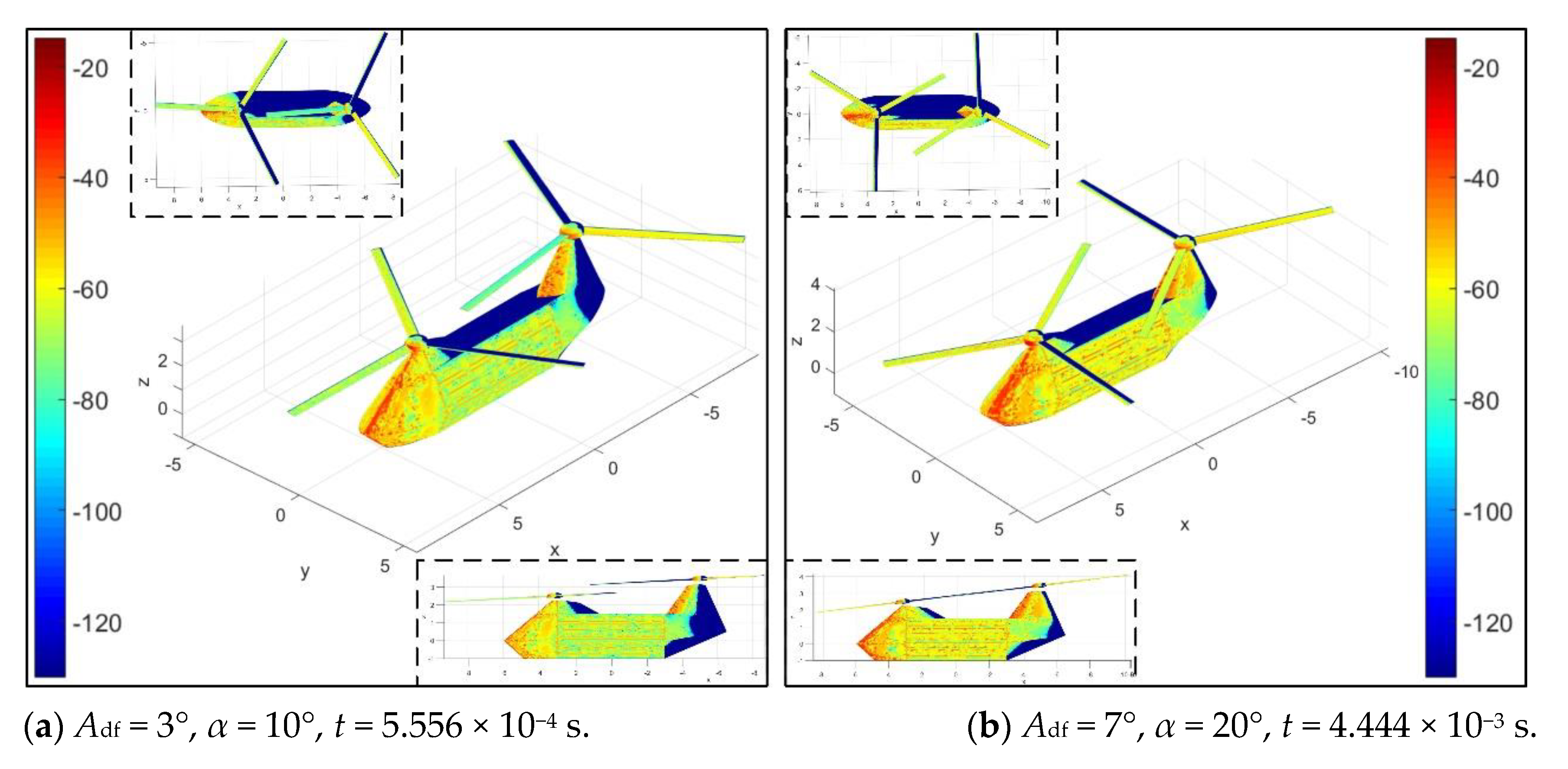
Figure 11 investigates that Adf mainly affects the distribution of scattering sources on the rotor surface under current conditions. For the case of Adf = 3°, at this time, the rotor has rotated 4°, the surface of the blades is green and yellow on the whole, and a small amount of red and yellow are distributed on the hub. When Adf is increased to 7°, darker red and orange-red appear in the illumination area of the propeller hub; because the propeller hub is designed as a rotating body, the influence of the azimuth angle and the rotation angle of the rotor on its RCS is negligible, while the change in the intensity of the scattering source on the surface of the hub is determined by the inclination of the rotor disc. Coupled with the influence of the upper position angle and the rotation of the rotor, the orange-red on the surface of the blade is obviously increased, and the green is greatly reduced, where the rotor has rotated 32°. As the azimuth angle increases from 10° to 20°, the red area of the nose and rotor tower base increases greatly, and the original main body green on the side of the fuselage is also replaced by orange and yellow. These results show that DAA can well describe the variation of scattering sources on the helicopter surface under different azimuth and rotor disc inclination.
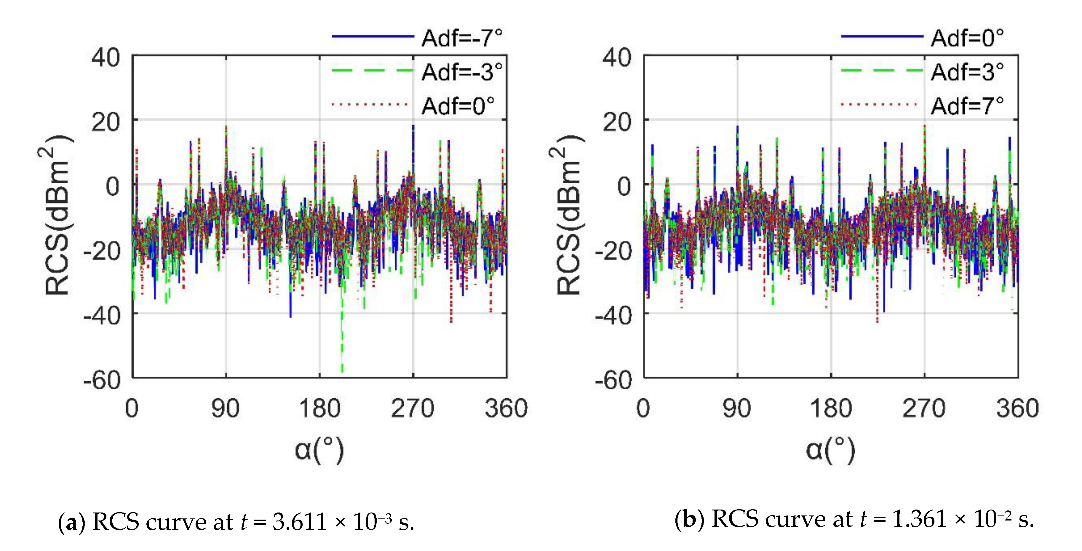
Figure 12 shows that the impact of different Adf values on helicopter RCS is mainly reflected in small peaks and local fluctuations and has little impact on large peaks and overall trends. For the curve at t = 3.611 × 10⁻³ s, the average of the RCS at Adf = −7° is −4.4673 dBm2, that at Adf = −3° is −3.8614 dBm2, and that at Adf = 0° is–3.6651 dBm2 because as Adf increases from −7° to 0°, the influence of the tip surface of the propeller and the front and rear edges of the propeller on the RCS indicator gradually increases. At α = 145.5°, the peak of the RCS curve at Adf = −7° is 0.7592 dBm2, while that at Adf = −3° is 3.445 dBm2; this is also due to the contribution of the scattering source on the surface of the blade. For the case of t = 1.361 × 10⁻² s, the RCS means of Adf = 0° is −3.7076 dBm2, that of Adf = 3° is −3.8724 dBm2, and that of Adf = 7° is −4.3679 dBm2, because, with the increase of Adf from 0° to 7°, the strong scattering source of the propeller tip is continuously weakened. Although the propeller hub brings adverse effects, the entire rotor disc is beneficial to deflect the radar waves. These results show that the influence of the forward tilt of the main rotor on the helicopter RCS cannot be ignored.
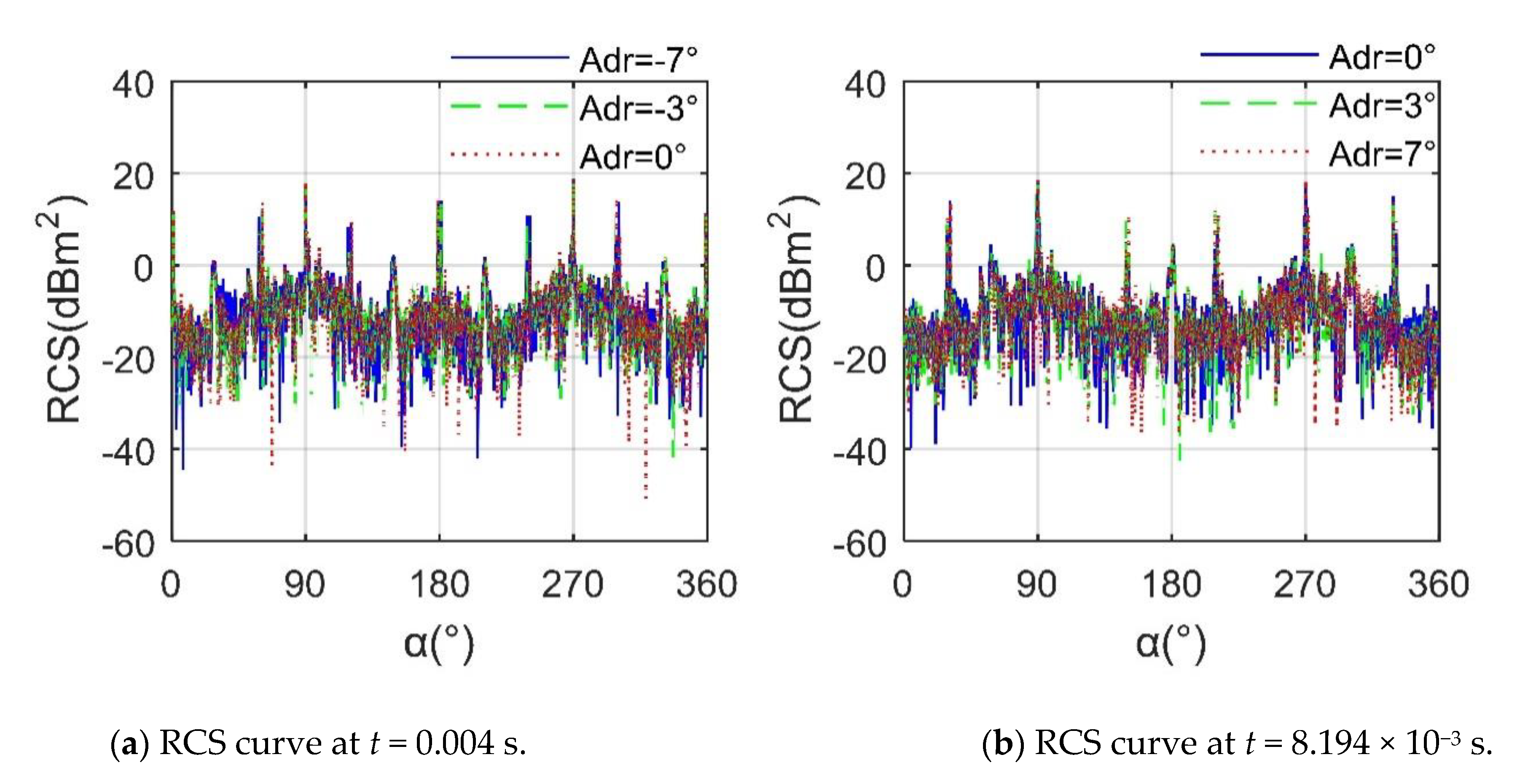
Figure 13 presents that the influence of different Adr on helicopter RCS is mainly reflected in small peaks and fluctuations in lateral azimuth. When t = 0.004 s, in the azimuth range of 37.75°~105.3° and 258°~309.5°, the three curves have an obvious difference, where the average RCS at Adr = −7° is −3.9581 dBm2, that at Adr = −3° is −3.9348 dBm2, and that at Adr = 0° is −3.8972 dBm2, because at this time the projection area of the rotor disk in the lateral direction is significantly increased, and then a larger illumination area and more scattering sources appear. For t = 8.194 × 10⁻³ s, the mean of the RCS curve at Adr = 0° is −4.2673 dBm2, that at Adr = 3° is −3.8744 dBm2, and that at Adr = 7° is −4.2225 dBm2, where within the range of 282.15°~315.5° azimuth, the three RCS curves are quite different, because the rotor is tilted to the negative direction of the y-axis, although the scattering characteristics of the blade tip are improved, the RCS performance of the hub in this lateral direction is higher. These results show that DAA can well capture the effect of rotor disk tilt on the helicopter. Although the rotor adopts a preliminary stealth design, the effect of the rotor disk tilt on the helicopter RCS is also obvious.

4.4. Influence of Attitude Angle

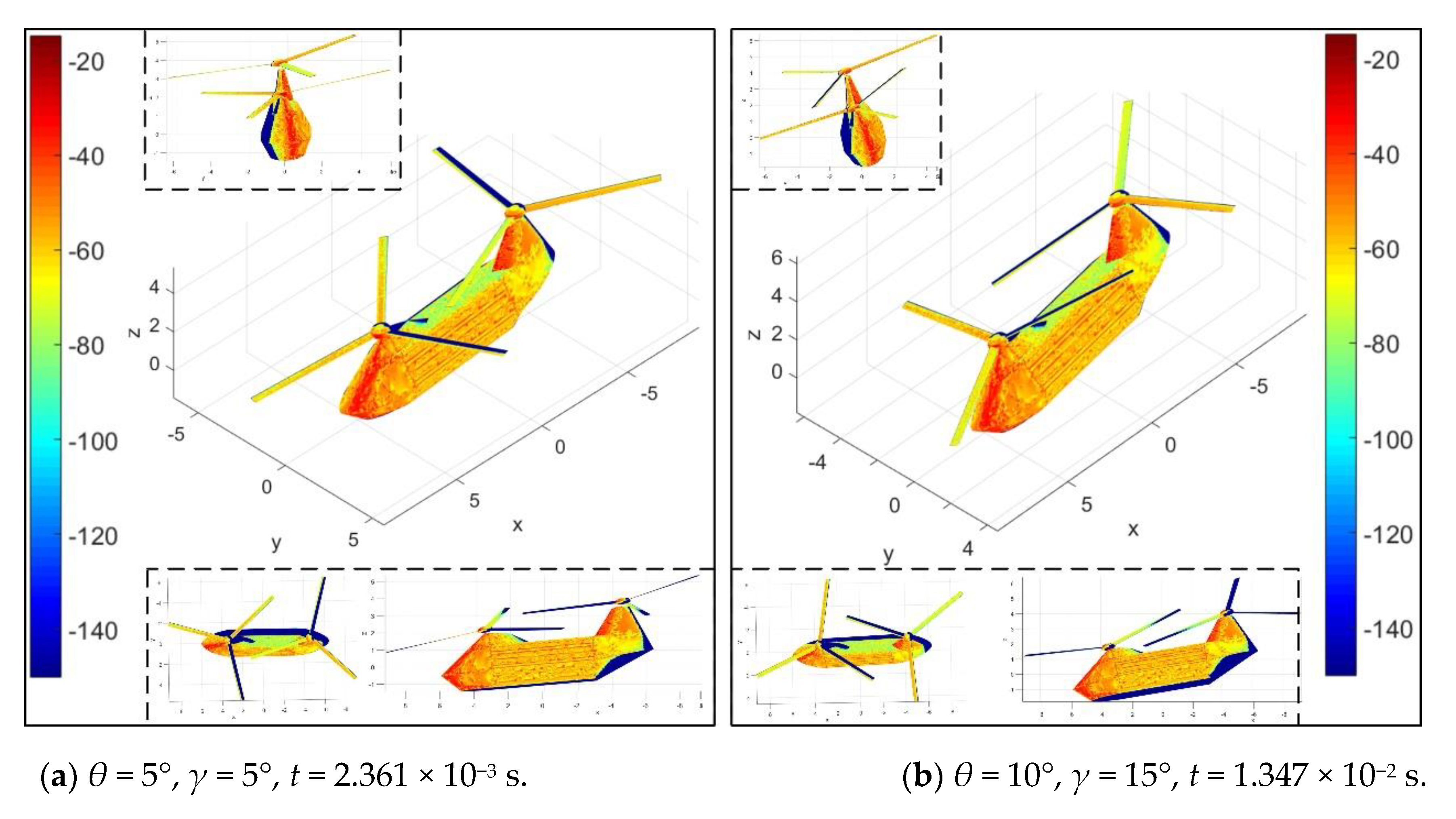
Figure 14 shows the attitude angle has a great influence on the electromagnetic scattering characteristics of the helicopter surface under current conditions, which mainly reflects on the nose, rotor tower and blades. For θ = γ = 5° and t = 2.361 × 10⁻³ s, the rotor has rotated 17°, where the strong scattering sources are mainly concentrated in the front of the nose, the front edge of the front tower, the front side of the rear tower and the front side of the hub. The side of the fuselage is orange and yellow, and orange and green are present on the surface of the blade. When θ = 10°, γ = 15° and t = 1.347 × 10⁻² s, the attitude angle of the fuselage has been increased, and the rotor has rotated 97°, the red color of the front hub decreases because of the occlusion of the blade roots, the red color of the rear hub increases slightly, the light yellow on the top of the fuselage increases sporadically, and the green at the rear of the fuselage has a small area increase. The positive increase of the pitch angle is conducive to the reduction of the RCS of the lower surface of the nose, but it is not good for the RCS level of the upper surface of the nose. For the roll angle, the positive increase is beneficial to the partial deflection of the radar wave on the side of the fuselage at this time, while it is not welcome to the top and the lower half of the side of the fuselage. These results show that DAA can well describe the transfer of scattering source distribution on the fuselage surface when the attitude angle changes.
Figure 15 provides that there are obvious differences in the RCS~α and RCS~t curves of helicopters at different attitude angles. For t = 7.5 × 10⁻³ s, the overall trend and fluctuation range of the two RCS curves are similar, while the average value and peak value are quite different, where the RCS means of the curve under θ = γ = 2° is −4.4013 dBm2, and that under θ = γ = 6° is −3.8202 dBm2, the main reason for the increase in the RCS index is the contribution of the large-area strong scattering source on the curved surface near the nose. There are 8 peaks exceeding 10 dBm2 on the θ = γ = 2° curve, and this indicator is 6 on the θ = γ = 6° curve, where the maximum value of the former curve is 17.99 dBm2 at α = 270°, while that of the latter is 15.57 dBm2 at α = 86.25°. For α = 27°, the main difference between the two curves is reflected in the peak size and fluctuation range, where the RCS means of the curve at θ = 3° and γ = 5° is −10.1944 dBm2, that of the other is −4.6993 dBm2, the main factors for the increase of this RCS index include the enhancement of scattering sources on the lower part of the side of the fuselage, the top of the fuselage, the leading edge of the rotor tower, and the hub. These results indicate that the helicopter’s RCS is unpopular at a larger attitude angle, and the fluctuation range of its dynamic RCS is also undesirable.

4.5. Doppler Feature Analysis

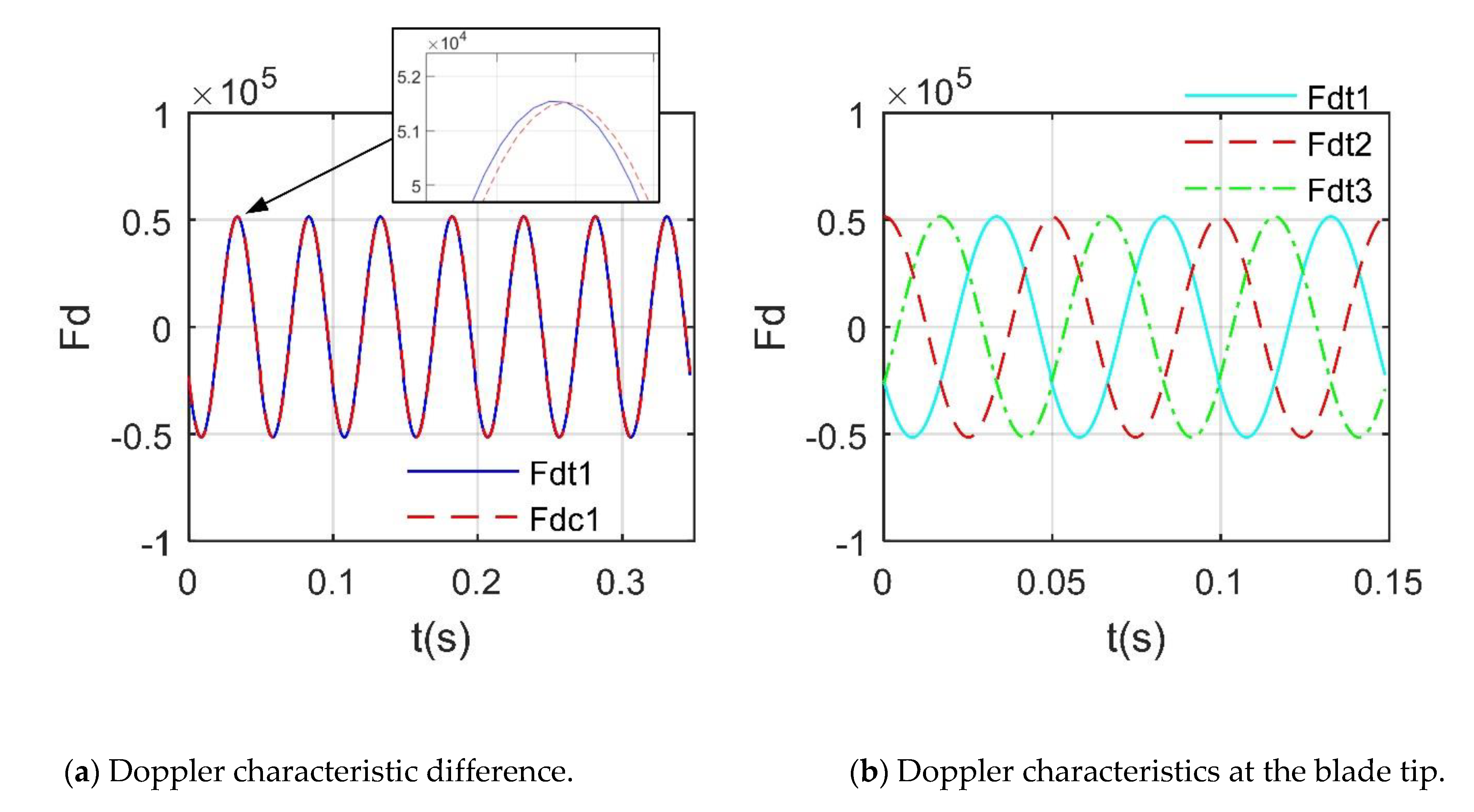
Figure 16 shows that the normalized RCS compresses most of the original smaller values [10,27]. For the rotor RCS, the maximum reaches 53.34 dBm2, where the smaller peaks are 13.36 dBm2 and 8.27 dBm2. After normalization, only 6 new peaks appeared within 0~0.1 s, and the original small peaks were submerged because the maximum and minimum values of RCS are too different. Figure 17 provides that the maximum value of Fdt is 515.493 × 10² Hz, slightly larger than fdmax (515.221 × 10² Hz), where Fdt1 is the Doppler frequency at an intersection point (recorded as P1) of the first blade tip and the leading edge, Fdc1 is the Doppler frequency at the center of the first blade tip, the first blade is the blade along the x-axis in the initial state [28,29]. This rotor 1 is composed of 3 blades, the tip of each blade will produce the most significant Doppler feature, and the extraction of other Fdt information is shown in Figure 17b. It can be found that in a minimum period, there are 3 maximums and 3 minimums, which represents the alternating Doppler frequency of the 3 blade tips during the rotation. These results show that it is feasible and accurate for DAA to analyze the Doppler characteristics of the rotor.

5. Conclusions

Based on the presented dynamic analysis approach, the factors affecting the radar cross-section in the X-band of the tandem helicopter are studied and discussed in detail. Through these investigations and analyses, the following conclusions can be drawn:
(1) In the current band, the dynamic RCS average index of the helicopter under a given heading azimuth angle shows a decrease-increase-decrease change with the increase of the radar wave frequency;
(2) The RCS of the rotating rotor shows strong dynamic characteristics and obvious periodic characteristics under a given head azimuth angle while increasing the rotation speed can reduce this dynamic period;
(3) The RCS of the rotor and the helicopter under different observation angles are obviously different. The positive increase of the elevation angle has a greater impact on the peak and the average value of the helicopter’s RCS;
(4) The inclination angle of the rotor disc mainly affects the small peak value of the helicopter RCS. A larger attitude angle will adversely affect the peak, maximum value and dynamic characteristics of the helicopter RCS.

Author Contributions

Conceptualization, Z.Z. and J.H.; methodology, software, validation, Z.Z.; formal analysis, investigation, Z.Z. and J.H.; data curation, writing—original draft preparation, Z.Z.; writing—review and editing, Z.Z. and J.H.; visualization, supervision, project administration, funding acquisition, Z.Z. All authors have read and agreed to the published version of the manuscript.

Funding

This work was supported by the Project funded by the China Postdoctoral Science Foundation (Grant Nos. BX20200035, 2020M680005).

Institutional Review Board Statement

Not applicable.

Informed Consent Statement

Not applicable.

Data Availability Statement

Not applicable.

Acknowledgments

Thanks to Professor Jun Huang for guiding the research work.

Conflicts of Interest

The authors declare no conflict of interest.

References

  1. Niu, L.; Xie, Y.; Wu, P.; Zhang, C. ARCS: Active radar cross section for multi-radiator problems in complex EM environments. Sensors 2020, 20, 3371. [Google Scholar] [CrossRef] [PubMed]
  2. Chen, J.; Zhu, Q.; Wang, K.; Zhu, Z.; Shen, S. Aerodynamic characteristics analysis of twin-rotor in tandem helicopter. Adv. Aeronaut. Sci. Eng. 2020, 11, 167–176. [Google Scholar]
  3. Zhou, Z.; Huang, J. Influence of rotor dynamic scattering on helicopter radar cross-section. Sensors 2020, 20, 2097. [Google Scholar] [CrossRef] [PubMed] [Green Version]
  4. Yu, Q.; Zhan, J.; Lv, C. Analysis of key technology and development trend of foreign tandem helicopter. Helicopter Technol. 2010, 1, 57–61. [Google Scholar]
  5. Zhou, Z.; Huang, J.; Wu, N. Acoustic and radar integrated stealth design for ducted tail rotor based on comprehensive optimization method. Aerosp. Sci. Technol. 2019, 92, 244–257. [Google Scholar] [CrossRef]
  6. Alhaji Musa, S.; Raja Abdullah, R.S.A.; Sali, A.; Ismail, A.; Rashid, N.E.A. Low-Slow-Small (LSS) Target Detection Based on Micro Doppler Analysis in Forward Scattering Radar Geometry. Sensors 2019, 19, 3332. [Google Scholar] [CrossRef] [Green Version]
  7. Huang, S.; Lin, Y.; Huang, J.; Zhao, Q.; Li, M. Experimental investigations on flow field and performance of tandem rotors. J. Nanjing Univ. Aeronaut. Astronaut. 2011, 43, 363–368. [Google Scholar]
  8. Zhou, Z.; Huang, J.; Wang, J. Radar/infrared integrated stealth optimization design of helicopter engine intake and exhaust system. Aerosp. Sci. Technol. 2019, 95, 105483. [Google Scholar] [CrossRef]
  9. Li, J.; Zhang, M.; Jiang, W.; Wei, P. Improved FBAM and GO/PO Method for EM Scattering Analyses of Ship Targets in a Marine Environment. Sensors 2020, 20, 4735. [Google Scholar] [CrossRef]
  10. Ye, S.B.; Xiong, J.J. Dynamic RCS Behavior of Helicopter Rotating Blades. Acta Aeronaut. Astronaut. Sin 2006, 27, 816–822. [Google Scholar]
  11. Linghu, L.; Wu, J.; Wu, Z.; Wang, X. Parallel computation of EM backscattering from large three-dimensional sea surface with CUDA. Sensors 2018, 18, 3656. [Google Scholar] [CrossRef] [PubMed] [Green Version]
  12. Li, G.; Cao, Y.; Zhong, G. Rotor icing model and trim characteristics analysis for tandem helicopter. J. Beijing Univ. Aeronaut. Astronaut. 2010, 36, 1034–1038. [Google Scholar]
  13. Guo, L.; Zhang, X.; Yao, D.; Yang, Q.; Bai, Y.; Deng, W. A single-dataset-based pre-processing joint domain localized algorithm for clutter-suppression in shipborne high-frequency surface-wave radar. Sensors 2020, 20, 3773. [Google Scholar] [CrossRef] [PubMed]
  14. Wang, Y.; Zhu, J.; Sun, Z. Unmanned tandem helicopter simulation. J. Tsinghua Univ. Sci. Technol. 2003, 43, 83–85, 93. [Google Scholar]
  15. Zhou, Z.; Huang, J.; Wang, J. Compound helicopter multi-rotor dynamic radar cross section response analysis. Aerosp. Sci. Technol. 2020, 105, 106047. [Google Scholar] [CrossRef]
  16. Yu, Q. Comparative analysis of tandem helicopter and single rotor helicopter. Helicopter Technol. 2008, 2, 62–68. [Google Scholar]
  17. Li, G.; Cao, Y.; Yang, Q. Analysis for determining trim, stability and control ability of tandem helicopter. J. Beijing Univ. Aeronaut. Astronaut. 2009, 35, 74–77. [Google Scholar]
  18. Zhou, Z.; Huang, J.; Wang, J. Electromagnetic scattering characteristics of coaxial helicopter based on dynamic transformation method. Chin. J. Aeronaut. 2020. [Google Scholar] [CrossRef]
  19. Zhang, H.; Shi, Q.; Yu, S. Design and simulation of tandem helicopter control law based on Dspace. Helicopter Technol. 2011, 3, 29–32. [Google Scholar]
  20. Galati, G.; Pavan, G.; Wasserzier, C. Characterization of Back-Scattering and Multipath in a Suburban Area after the Calibration of an X-Band Commercial Radar. Sensors 2020, 20, 463. [Google Scholar] [CrossRef] [Green Version]
  21. Yan, Q.; Sheng, S.; Lin, Q. Unmanned Tandem Helicopter Robust Guaranteed Cost Controller. Ordnance Ind. Autom. 2018, 37, 34–38. [Google Scholar]
  22. Balal, N.; Balal, Y.; Richter, Y.; Pinhasi, Y. Detection of Low RCS Supersonic Flying Targets with a High-Resolution MMW Radar. Sensors 2020, 20, 3284. [Google Scholar] [CrossRef] [PubMed]
  23. Guo, J.; Yin, H.C.; Ye, S.J.; Man, L.; Jia, Q. Novel technology for electromagnetic characteristic simulation of helicopter blades. Acta Aeronaut. Astronaut. Sin 2019, 40, 322732. [Google Scholar]
  24. Han, Q.; Pan, M.; Long, W.; Liang, Z.; Shan, C. Joint Adaptive Sampling Interval and Power Allocation for Maneuvering Target Tracking in a Multiple Opportunistic Array Radar System. Sensors 2020, 20, 981. [Google Scholar] [CrossRef] [Green Version]
  25. Li, Y.; Liu, Y.; Wang, Y.; Lin, Y.; Shen, W. The Millimeter-Wave Radar SLAM Assisted by the RCS Feature of the Target and IMU. Sensors 2020, 20, 5421. [Google Scholar] [CrossRef]
  26. Zhou, Z.; Huang, J.; Yi, M. Comprehensive optimization of aerodynamic noise and radar stealth for helicopter rotor based on Pareto solution. Aerosp. Sci. Technol. 2018, 82, 607–619. [Google Scholar] [CrossRef]
  27. Su, C.; Ishimaru, A.; Kuga, Y. Time-domain analysis of multiple scattering effects on the radar cross section (RCS) of objects in a random medium. Waves Random Complex Media 2020. [Google Scholar] [CrossRef]
  28. Pouliguen, P.; Lucas, L.; Muller, F.; Quete, S.; Terret, C. Calculation and Analysis of Electromagnetic Scattering by Helicopter Rotating Blades. IEEE Trans. Antennas Propag. 2002, 50, 1396–1408. [Google Scholar] [CrossRef]
  29. Gordon, W.B. Far—field approximations to the Kirchhoff—Helmholtz representations of scattered fields. IEEE Trans. Antennas Propag. 1975, 23, 590–592. [Google Scholar] [CrossRef]
Figure 1. Schematic diagram of dynamic electromagnetic scattering of the tandem helicopter.
Sensors 21 00271 g001
Figure 2. The validation of the radar cross-section (RCS) algorithm on rotor 1, fRH = 10 GHz, β = 10°.
Sensors 21 00271 g002
Figure 3. Tandem helicopter model and its size distribution.
Sensors 21 00271 g003
Figure 4. Model and size distribution of rotor 1.
Sensors 21 00271 g004
Figure 5. High-precision mesh on the surface of the helicopter model.
Sensors 21 00271 g005
Figure 6. Dynamic RCS of rotor 1 at different fRH, α = 30°, β = 5°, nr1 = 1200 r/min.
Sensors 21 00271 g006
Figure 7. Periodic characteristics of dynamic RCS of rotor 1, fRH = 10 GHz, β = 5°, nr1 = 1200 r/min.
Sensors 21 00271 g007
Figure 8. Electromagnetic scattering characteristics of rotor 1, fRH = 10 GHz.
Sensors 21 00271 g008
Figure 9. Dynamic RCS of rotor 1 at different azimuths, fRH = 10 GHz, β = 5°, nr1 = 1200 r/min.
Sensors 21 00271 g009
Figure 10. RCS of helicopter at various β, fRH = 10 GHz, nr1= nr2 = 1200 r/min, Adf = Adr = 0°, γ = θ = 0°.
Sensors 21 00271 g010
Figure 11. Surface scattering characteristics of helicopter at various Adf, fRH = 10 GHz, nr1= nr2 = 1200 r/min, β = 0°, Adr = 0°, γ = θ = 0°, RCS unit: dBm2.
Sensors 21 00271 g011
Figure 12. RCS of helicopter at various Adr, fRH = 10 GHz, nr1= nr2 = 1200 r/min, β = 0°, Adr = 0°, γ = θ = 0°.
Sensors 21 00271 g012
Figure 13. RCS of helicopter at various Adr, fRH = 10 GHz, nr1= nr2 = 1200 r/min, β = 0°, Adf = 5°, γ = θ = 0°.
Sensors 21 00271 g013
Figure 14. Surface scattering characteristics of helicopter at various attitude angles, fRH = 10 GHz, nr1= nr2 = 1200 r/min, α = 25°, β = 0°, Adf = Adr = 5°, RCS unit: dBm2.
Sensors 21 00271 g014
Figure 15. RCS of the helicopter at various attitude angles, fRH = 10 GHz, nr1= nr2 = 1200 r/min, β = 0°, Adf = Adr = 7°, RCS unit: dBm2.
Sensors 21 00271 g015
Figure 16. RCS of the rotor 1, α = 27°, β = 0°, Adf = Adr = 0°, fRH = 10 GHz, Vm = 0 m/s, nr1= 1200 r/min.
Sensors 21 00271 g016
Figure 17. Doppler feature of the rotor 1, α = 27°, β = 0°, Adf = Adr = 0°, fRH = 10 GHz, Vm = 0 m/s, nr1= 1200 r/min.
Sensors 21 00271 g017
Table 1. The main dimensions of the helicopter model.
ParameterLfusWfusHfusLfnRr1
Value (m)12.52.74.16366.15
ParameterRr2Ht1Ht2Xr1Xr2
Value (m)6.150.7611.6633.15.02
Table 2. Main dimensions of rotor 1.
ParameterAirfoilCb0 (m)At0 (°)At1 (°)Cb1 (m)
ValueTSAGI 8%0.41230.4
ParameterRh1Rh2Rh3Rh4Hhub
Value (m)0.2930.470.390.20.29
Table 3. Dynamic RCS mean of rotor 1 at different fRH, α = 30°, β = 5°, nr1 = 1200 r/min.
fR/GHz89101112
Mean RCS (dBm2)−7.8077−8.1684−7.9870−8.1797−8.7597
Publisher’s Note: MDPI stays neutral with regard to jurisdictional claims in published maps and institutional affiliations.