1. Introduction
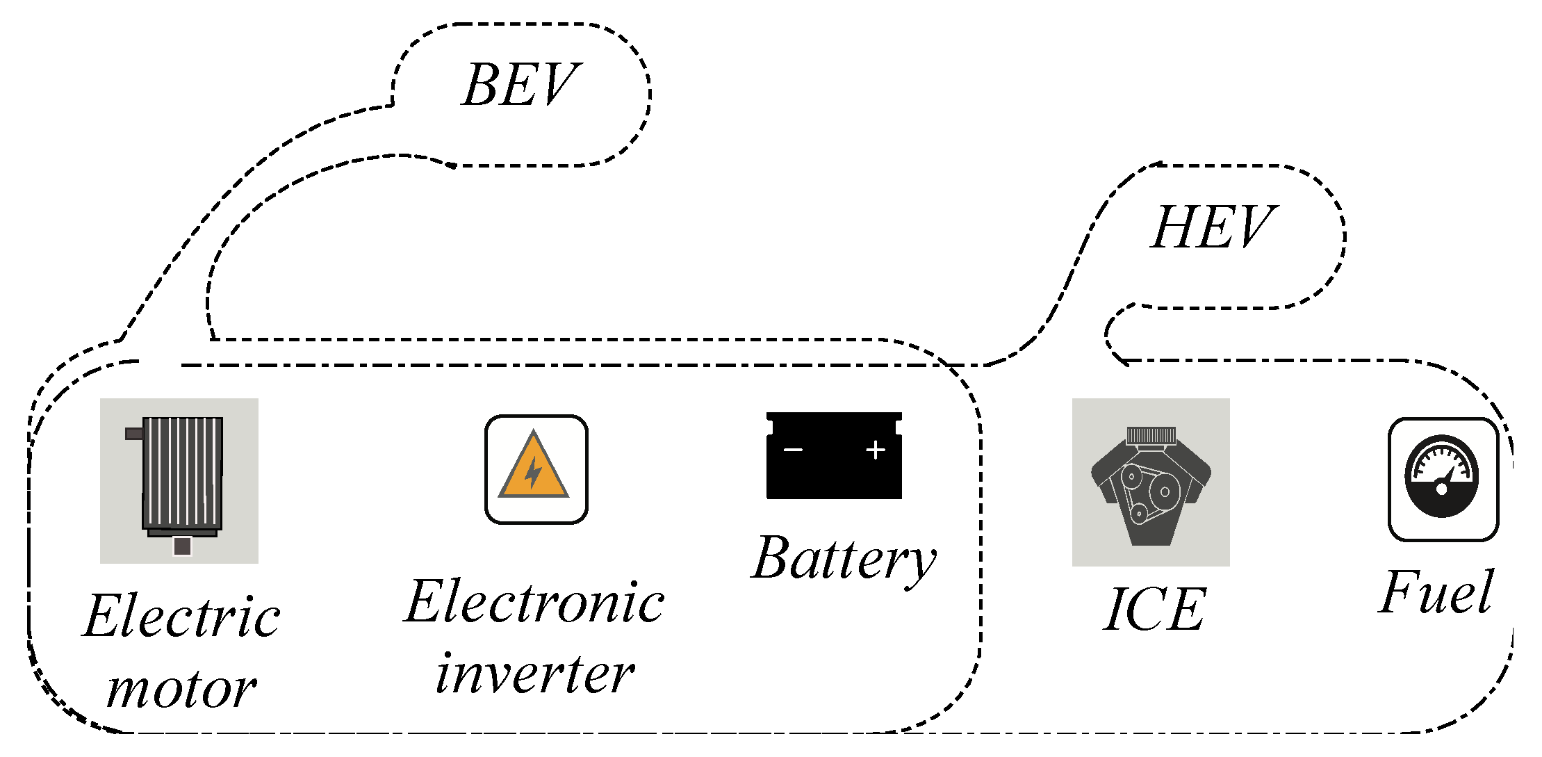
The area of electric vehicles (EVs) is becoming increasingly relevant in this decade. The majority of transportation applications are electrified and employ an electrical powertrain to supply the necessary mechanical power to these tools [
1]. This equipment is often built around an electrical machine linked to an electronic converter that regulates the motor speed dependent on the acceleration requirement [
2]. There is also a power pack battery within, which serves as the primary energy source in the event of a pure electric car. This principle energy source must be refilled whenever it is exhausted. Actually, the discharging curve is determined by various factors, including the acceleration form utilized, the battery’s lifetime, the charging/discharging cycle, the battery temperature, and the initial state of charge when the battery is charged [
3,
4]. Thus, the major of researchers try finding useful solutions for improving the battery lifetime by minimizing the recharge/discharge number or increasing the vehicle autonomy by reducing the quantity of the consumed power from the main energy source, especially by making the recharge action easier. This goal was to assist in developing a wireless power transfer (WPT) technology that might be used to charge an electric vehicle. In this field, the research was not stopped, and more than applications and solutions were presented to improve the performances of this kind of recharge tool [
5].
Basing on the conductors’ feedback and the electric car manufacturer’s trends, which is based on the utility and the simplicity of the recharge tool use and how this recharge solution can help increasing selling electric vehicle into the world, the WPT principle can be a useful solution [
6,
7]. But this technology must be more robust and must have a better energetic rentability. The conventional solution is based on only one receiver placed undo the vehicle, and this prototype does not give enough power. This is conducted to search how it is possible integrating two receivers to undo the car and test the efficiency of this solution. This approach cannot be used until testing is performed to determine how the magnetic field influences the two linked coils and what parameters can impact the entire system.
The leading technology of the wireless energy transmission between a primary and a secondary coil was firstly proposed by Kurs [
8]. This system was found suitable and applicable for electric vehicle recharge applications [
9]. Basically, wireless charging was applied for stationary cases, and its efficiency was proved. However, the quantity of transferred energy depends on the coil’s size and inverter performances [
10,
11]. The coil to coil case was tested in more than a technical review, and the only relation between the number of inductance turns is studied for searching about the efficiency [
12]. From the other side, this system was studied by working on the different circuit topologies that can be used to affect the system performances [
13]. These studies were searched to improve the versions of this WPT technology, but the possibility of using two receivers’ coils was not tested and mainly studied. Some researchers have investigated the use of more than coil applications for some Biomedical applications [
14]. The results showed the importance of this addition and proved some related problems related to the resonance between the coils. This is also discussed by the authors of [
15,
16].
Moreover, working on the coils form was a severe challenge for researchers. The major of the existing literature was used the rectangular coil to form the main structure, due to its immense power. However, placing two closed receiver coils was found difficult in these versions [
17,
18,
19,
20]. Actually, the measurement tool of these systems is not very easy, and it needs an initial check for the given performances before starting use.
Based on the previous information and by showing the different works of literature, the wireless recharge system has several weaknesses in relation to the coils centralization and then appeared problem in relation to the recharge time or the power losses. Moreover, the standard version, which bases on only one receiver and only one transmitter, has shown a fewer performance in relation to the recharge time for the electrical transportation system, as the electric vehicle. Therefore, studying the possibility of having two coils receiver under an electric vehicle seems essential to test the actual efficiency of this kind of wireless recharge upgrade. Furthermore, as the placement of two coils in serial, can present a problem regarding the mutual flux, the energetic global performances will be affected. This study gives a detailed analysis and discussion regarding these problems and shows what kind of problem can appear. Finally, it recommends using this upgraded version of the wireless recharge solution.
This paper provides a comprehensive analysis of coil placement in space and demonstrates what benefits may be obtained if more than one receiver coil is utilized for the same transmitter. This study employed the Maxwell tool to display the magnet flux inside and around the coil and the potentially usable space for energy feedback. The forms of flux vectors from the transmitter to the receivers are shown and explained. This gives information about the movement of flux in the field around the coils. At the end of this analysis, the reader will find useful information for correctly modeling the wireless transmitter and have information about the exigence for using a double coil receiver to face the only one coil receiver. The statics of the utility of the double receiver coils face the only one receiver coil on the electric vehicle autonomy is shown at the end and show the weakness and advantages of each proposal.
For having the paper goal, the manuscript is organized as follows. After the introduction section, a general paragraph is implemented, which describes the relationship between the electric vehicle and the wireless recharge method. In the third section, the overall architecture of the principle of the magnetic recharge system is presented. This is by showing the different possible topologies. The fourth section shows the mathematical model of the induction charger system and explains the equations used to quantify the final outputted power. The fifth section shows the main objective of this paper. It contains all the analysis results made on the positions of the coils and dimensions. It also contains the needed information about the practice application, which validates the analysis study made with the Maxwell tool. In the end, the conclusion section concludes the paper by resuming the continent and showing future endeavors.
5. Impacts of Coil Position and Receiver Coil Number on the WPT Performance
In this section, the performance of the wireless Power Transfer is evaluated according to various external and internal parameters related to the receiver face, the transmitter position, and accordingly to the number of coil receivers. The Ansys Maxwell application is used for applied all of these variables and evaluated the magnetic field value.
5.1. Transmitter/Receiver Coil: Design and Parameters
Initially, it is mandatory to design correctly the coils that will be used as receivers and/or transmitters. This is must be adapted to the desired application. In this studied case, the design of the coils must be adaptable to be placed undo the vehicle body. Thus,
Table 2 regroups all this information and given what is the dimension of the coils [
30,
31].
Figure 6 also gives the design applied to Maxwell.
After showing these specifications on the coil, it is critical to cite what kind of parameters must be supervised to study the coil coupling factor. For this objective, the coupling coefficient, the mutual inductance, and the coil self-inductance are the factors that will be supervised and discussed. These variables will be studied according to the coil-to-coil relative location, and the coil structural parameters.
This study needs complicated mathematical analysis work, and this can be guaranteed by a computational calculation method as the Finite element analysis solution (FEA). Thus, using the Ansys Maxwell tool, a variety of solvers for evaluating the electromagnetic part design can be applied.
With Maxwell’s application, this section tries to study the effect of the variation between the coils in the vertical position. Thus, it appears to the positive or negatively coupling. The results show the analysis of the coupling coefficient and the mutual inductance between the transmitting and receiving coils. The built model can be seen in
Figure 7.
Figure 6 depicts the distribution of magnetic flux density in the object field, which is a region with a core near the transmitter’s surface. The magnetic field distribution has symmetric properties because the coil structure is strongly symmetrical. Thus, the magnetic flux density near the Litz wire is high in this illustration, while it is low near the central field.
The primary and the secondary side coil models were designed using the Maxwell tool. The distance between the two-spool axis is variable, and then, the magnetic field simulations were applied for three different cases, as seen in
Figure 7. In the first case,
Figure 7a, shows the results of the horizontal coil offset, which is equal to 90%. In this study, to simplify the analysis of the system, the WPT consists of two identical circulating coils.
Figure 8 shows the three cases of coil pattern circulating for a gap equal to 100 mm.
The simulation of the coreless model was carried out using the Ansys Maxwell software by varying the distance z from 50 to 300 mm.
The overall measurement results of the coupling coefficient and the mutual inductance for the variation of the gap (−250/250 mm) are summarized in
Figure 7. The simulations indicate that the value of the coefficient coupling and the mutual inductance decrease as the vertical distance between the transmit and receive coils increases.
This implies that a little power is transferred as the distance between coils increases. A weakly coupled coefficient that characterizes this type of system is less than 0.2.
5.2. One Transmitter and One Receiver Coil: Magnetic Field Zones
The coupling coefficient in
Figure 8a shows the influence of the receiver face on the transmitter position. Even the two coils are centralized, and the coupling coefficient is high. This parameter decreases even the two coils center are shifted. At 200 mm the coupling coefficient will be null. When two circuits have a mutual inductance, noted M, it can be said that the two elements are magnetically coupled. This mutual inductance parameter depends on the proper primary and secondary inductances
Lp and
Ls, respectively. But their relative position affects too. Mathematically, the mutual inductance
M can be expressed, as seen in Equation (13).
with
k the coupling coefficient in
Figure 8a. Thus, according to the previous equation, the mutual inductance variation can be shown in
Figure 8b. It is clear that the perfect value is always related to the superposition of the two coils element.
Figure 9 shows the evolution of the magnetic flux for the case of only one receiver and one transmitter coil. All of the presented screens are taken for two different coil positions.
Figure 9a shows that the two coils center are centralized, and it is clear that the magnetic flux is parallel and approximately; all the yields are transferred. On the other hand, the deviation of the magnetic flux is clear for the cases where the two coils are not centralized, as seen in
Figure 9b. This situation was depicted for a distance between the two centers equal to 80 mm. Here, the two coils still have a contact zone, as we do not have over-crossed the coil radius. This is why we still have a magnetic zone between the two coils.
5.3. One Transmitter and Two Receivers Coils: Magnetic Field Zones
The two-coil receiver system is studied in this section. Moreover, using Maxwell software, the magnetic field evolution is studied, and this is for different cases related to the two-part positions. The built model consists of one coil transmitter, which has the same previous dimensions, cited in
Table 2, and the coils receivers, which also have the same performances as the transmitter coil. The distance between the two coils receivers center is 80 mm. As shown in
Figure 10a, that the quantity of the magnetic field in the receiver coils is very high as the red color is very concentrated in the centers of the coils. But this is also related to the superposition of the first coil transmitter and two receiver centers. Moreover, it is clear that the mutual magnetic fields are limited between 1.428 tesla as the best value and 1.075 tesla as a minimum value. The form of the magnetic yields is also shown in the same figure, and all yields are parallel.
For the previously cited coil specifications,
Figure 10b shows that the transferred magnetic field, cannot be assured as the distance between the two centers is high than the diameter of the one coil receiver.
Figure 10b shows the results of the distance between the receiver middle and the transmitter middle is 120 mm, proving why the yields cannot be transferred to the receivers. Moreover, in
Figure 10b, the concentration of the red color in the two receivers coils is related to the internal magnetic field that appears between the two receivers coils. However, the color in the transmitter coil is yellow, which means that there is no magnetic field inside. Moreover, the two coils yields do not move from one to the other part; it is just inside the same coil.
For
Figure 10c, the case of partial superposition is tested, and this is for 40 mm as applied spacing between the transmitter coil center and the two receivers coils center.
From the other side, the coupling coefficient for the case of two receivers coils is evaluated, using the given maxwell statistics.
Figure 11 shows the corresponding coupling coefficient for each coil proportionally to the transmitter coil position. For example, if the coil transmitter is in the middle of the two receivers coils, the magnetic coupling coefficient can be evaluated as 0.0026 for each coil, and the total will be multiplied by two. However, if the coil transmitter is superposed with the first coil receiver, the maximum coupling coefficient touches 0.0058, and it is the same if it is superposed with the left coil receiver. This is different from the case of only one receiver. It is clear that the range of magnetic coefficient for each coil is the same—but as there are two receivers, the total coupling coefficient will be a sum of two elements. For example, if the two receivers center is spaced from the one transmitter coil center by 0.25mm, then the total coupling coefficient is 0.04 and 0.018. The new total coupling coefficient will increase the efficiency of the WPT.
Figure 11a shows the mutual inductance evolution according to the only one coil receiver and the case of two coil receivers. Proportionally to the interpretation of the previous results, the total mutual inductance will be bigger when the two coils react to the given magnetic field from the transmitter. This is clear for the case, where the transmitter coil center is in the middle of the two receivers coils. Only one receiver coil will have a mutual inductance equal to 22.5 μH, and the same for the second coil—which gives 45 μH as the total mutual inductance. When the two receiver coils move from the center, the given results demonstrate that the high efficiency of the WPT still exists until 80 mm as a marge of variation. When moving more, the efficiency decreases proportionally and touches zero, when the distance is more than 200 mm. As seen in
Figure 8b, the totally mutual inductance is better for the case of two coils receivers. For example, for 110 mm as space between the two centers, the mutual inductance is 40 μH for the case of two receivers and 15 μH for the case of one receiver.
On the other hand, this study depicts the possible given power if only one receiver coil is used, and in the case of two receivers, coils were used.
Table 3 shows these statistics and resume, the importance of two receiver coils, where it is possible touching 96% of the maximum achieved efficiency. These statistics were depicted for the previously cited coil parameters, as shown in
Table 2.
6. Experimental Validation
In this simulation, the prototype operating two coils have two different proper inductances. The first coil has an inductance equal to 30 μH, and the second is 21.13 μH.
Figure 12 shows a real photo of the prototype, which the necessary measurement tool. The second, larger, coil is the transmitter part, and the second is the receiver part. In this test, the inputted voltage is equal to 35VDC transforms to an alternating voltage of frequency 50 kHz. The applied test simulates a coil placed undo the vehicle and moved into a different position face the transmitter coil. Moreover, the mutual inductance will be evaluated according to the one or two coils receivers mode.
Figure 12 shows this prototype. The real dimensions of the coils are summarized in
Table 4.
The given statistics validate the obtained results from the Maxwell application. Thus, if concentrating on the coupling coefficient and the mutual inductance, the importance of the wireless recharge system can be evaluated. For this practical validation, the best mutual inductance value remains constant at approximately 45 μH, until 180 mm as a maximum distance between centers is shown in
Figure 13. Whereas, the mutual inductance starts decreasing. Finally, over 200 mm, the mutual inductance comes to zero, and then it is proved that no energy will be transferred to the main charge connected to the receiver coils.


 ,
, 


