Abstract
The design and implementation of an electronic system that involves head movements to operate a prototype that can simulate future movements of a wheelchair was developed here. The controller design collects head-movements data through a MEMS sensor-based motion capture system. The research was divided into four stages: First, the instrumentation of the system using hardware and software; second, the mathematical modeling using the theory of dynamic systems; third, the automatic control of position, speed, and orientation with constant and variable speed; finally, system verification using both an electronic controller test protocol and user experience. The system involved a graphical interface for the user to interact with it by executing all the controllers in real time. Through the System Usability Scale (SUS), a score of 78 out of 100 points was obtained from the qualification of 10 users who validated the system, giving a connotation of “very good”. Users accepted the system with the recommendation to improve safety by using laser sensors instead of ultrasonic range modules to enhance obstacle detection.
1. Introduction
This research concerns the design and implementation of a position, speed, and orientation controller in a wheelchair simulation prototype through the use of graphical interface, inertial systems, and digital control algorithms. To introduce the topic, according to the World Health Organization (WHO), “Disability is the umbrella term for impairments, activity limitations and participation restrictions, referring to the negative aspects of the interaction between an individual (with a health condition) and that individual’s contextual factors (environmental and personal factors)” [1]. The causes of the functional performance impairments of the human body are linked to problems in pregnancy, growth, spinal cord injuries, and organ dysfunctions. Physical disabilities are associated with sedentary behavior [2], cerebral palsy, diplegia, dislocations, contractures, scoliosis [3], and spina bifida [4]. They also involve neural tube defects related to birth issues in the brain, vertebral column and/or spinal cord [5]. Therefore, the proposal of viable solutions to such impairments are desirable, allowing the use of assistance mechanisms that improve patient mobility.
According to the latest fact sheets from WHO, “over 1 billion people are estimated to live with some form of disability. This corresponds to about 15% of the world’s population, with up to 190 million (3.8%) people aged 15 years and older having significant difficulties in functioning, often requiring healthcare services. The number of people living with disability is increasing, in part due to ageing populations and an increase in chronic health conditions” [6].
Wheelchairs are considered as an assistance instrument and allow the mobility of a person with functional performance disability. They are classified into manual and automatic. The design and construction of a controller for an automatic wheelchair have been studied using different closed-loop control methods [7,8,9,10,11]. These designs are one of the major configurations of control systems based on instrumentation, analog, and/or digital electronics.
Automatic wheelchair digital controllers depend on the type of instrumentation used. There are non-invasive instrumentation systems placed on the user, such as those based on cerebral activity, like Brain Computer Interfaces (BCIs) [12,13,14], those based on inertial and magnetic sensors that measure head or hand movements [15,16,17], and those that implement Electrooculography (EOG) as well as Electromyography (EMG) [18,19], [20]. On the other hand, there are controller systems placed on the wheelchair like those that involve the use of distance sensors to detect obstacles or operate the wheelchair in closed environments [21,22,23], besides those that use vision artificial techniques [24,25,26]. There are other types of instrumentation that depend on the user characteristics, the wheelchair navigation, or the environment, being outdoors or indoors.
The structure of the article is made up of four stages: First, the wheelchair prototype instrumentation and the configuration of the IMOCAP-GIS motion capture system located on the user’s head; second, the mathematical model considering the dynamic systems model theory; third, manual and automatic control by means of intelligent control techniques to operate the prototype in seven directions: Forward, backward, right, left, back-right, back-left, and stop; fourth, a safety control using distance sensors to detect static obstacles. Finally, the evaluation of the performance through a laboratory test protocol that validates the system and user experience.
This work is part of an ongoing investigation. It began with a systematic review developed in [27], in addition to the development of the proposed system in a wheelchair prototype, the upcoming implementation in an electric-powered wheelchair, and experimental tests with users with disabilities in lower and upper limbs.
2. Background and Related Works
Wheelchair control systems use different types of instrumentation and control techniques, including head motion controllers that operate a prototype or wheelchair, as indicated by the state of the art that was carried out in [27]. Designs and implementations of controllers were also defined based on the research development of different universities as mentioned by [28]. Among instrumentation types mentioned in the literature review, an important topic is the use of inertial-magnetic sensors to detect body movements, specifically head movements. This type of control does not involve upper limbs movements, thus people with upper/lower limbs disabilities can use this system.
Ruzaij et al. [29] developed a system to operate the wheelchair through an intelligent application with two operation modes: Voice commands and head movements. The sensors used were microelectromechanical systems (MEMS). The design has a compensation speed system in case of going through ascending or descending a ramp, and it depends on the user tilt angle [30]. A calibration algorithm of the user’s head orientation is used if the road does not have flat surfaces [8]. The system was validated by 10 participants to measure the controller accuracy [31].
Nasif and Khan [32] implemented a digital control using accelerometers to capture head movements. The sensors were placed on a cap to control five directions, and the data were sent by using radio frequency.
A multimodal interface control was developed by Fall and Latour [33] to be used for people with disabilities in upper limbs. The system is based on wireless sensor network. They developed a fusion algorithm for head movements using inertial sensors that were placed on earphones, and the communication system was realized using WiFi.
Marins et al. [34] used an Inertial Movement Unit (IMU) to capture user’s movements and operate the wheelchair. Data processing was carried out in Arduino and data classification using neural networks was developed in MATLAB®. The system was simulated in a closed environment with obstacles.
Prasad et al. [35] implemented a system with head movements in four directions. The system was controlled using an iOS application sending data to the motors.
Errico et al. [36] developed an interface in which a wheelchair is operated with head movements. The sensors were placed in a cap, and the movement directions were sent using radio frequency. The interface has an emergency button to make a call in the event of an accident. Other buttons of the system operate the wheelchair both indoors and outdoors.
Kader et al. [9] used 3-axis accelerometers to detect head movements. In addition, they implemented sonar sensors to detect obstacles in front or behind of the wheelchair, to avoid accidents. In case of emergency, the system sends a message using Global System for Mobile communications (GSM) to alert the family. The system has five directions, including Stop.
A control system was developed by Dey et al. [37]. The system has a seat belt to improve the safety of the user. Furthermore, it has ultrasonic sensors that detect obstacles. The wheelchair is powered by a solar panel, and uses sensors to be operated in case of improper head movements.
Manta et al. [26] realized a wheelchair command interface based on head movements. The system has two control modes, using simple commands and head movements. A 3D cartographic system is used to avoid obstacles. The control was based on an artificial vision system.
Other systems involve IMUs embedded into wearable devices, which have been used to athletes, in medical rehabilitation devices, among others. For this reason, some articles that have worked with IMUs in different areas are mentioned below.
Ayman et al. [38] recognized human activity by locating sensors on the hand, extracting multimodal data, in order to obtain healthier lifestyles. The activities carried out for the analysis were washing windows, cutting with a knife, eating, playing on a computer, and sending text messages using a keyboard and a pen. The fusion of gyroscope and magnetometer data allowed achieving an accuracy of 97.84% compared to other sensors. The combination of all the sensors in the system increased the accuracy to 98.87%. This accuracy indicates that sensor fusion was capable of improving daily human activity recognition rates.
Philpott et al. [39] developed an inexpensive and easy-to-use monitoring device within the sprint athletics community. Coaches monitor starting characteristics, allowing the coach to make technical adjustments. Twenty-five sprint start tests were done. The unit of measurement was accurate to 0.025 ± 0.024 s. Acceleration readings were higher, ranging between 1.15–2.60 m/s2, with a mean of 1.81 m/s2. An additional feature of this specific IMU allows the data to be provided to the user in real time, allowing the coach and the athlete to receive meaningful and useful in-training that can be implemented in their performance.
Setiawan et al. [40] designed a device to measure gait pattern using seven IMU (MPU6050 gyroscope and accelerometer). Communication is wireless. The recent interface design will improve heel strike, flat foot, heel lift off, and toe lift off. In this work, inertial sensors were used which provide Euler angles, analyzing gait and obtaining parameters for the rehabilitation of patients.
Gómez et al. [41] developed an IMU-based physical interface to measure foot attitude and a graphical interface that acts as a visual guide for patient rehabilitation. The data are displayed while the user performs dorsiflexion, flexion, eversion, and planar inversion movements. It can be used for therapy processes where the professional in charge refeeds the exercises based on the data collected. The best resolution ranges for data collection were ±2 gravities and ±250°/s. Rehabilitation could be achieved by reducing the variation in the angular position of the foot during therapy.
Gujarathi and Bhole [42] developed a gait analysis method to detect factors such as floor contact and non-contact. The experimental tests were based on walking a straight corridor with a distance of 40 m, and the data are processed in an algorithm to extract the period of events. The results identify the biomechanics of patients after surgeries. According to the authors, the sensor is effective for data acquisition and improves accuracy for gait analysis.
3. Materials and Method
The system configuration is described in this section. Section 3.1 describes the prototype electronic instrumentation and the transmission of data using the User Datagram Protocol (UDP). Section 3.2 describes the motion capture system configuration. The motion capture system IMOCAP-GIS was developed in the Software Research Group (GIS) at the Universidad Pedagógica y Tecnológica de Colombia (UPTC) [43]. Section 3.3 describes the transfer data method from the prototype to the computer.
3.1. Electronic Instrumentation of the Wheelchair Simulation Prototype
The wheelchair prototype instrumentation involves sensors, a control unit, actuators, a chassis, and communication protocols that were implemented for the correct performance of the system. The sensor distribution, control unit, communication modules, and actuators connected to the microcontroller are shown in Figure 1.
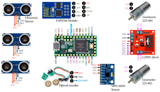
Figure 1.
Devices connected to the microcontroller Teensy® 3.2.
The prototype has a communication system through a WiFi module using UDP to operate the motors, considering their speed and direction, which are established through Pulse Width Modulation (PWM). Table 1 shows the command that receives the speed and direction to drive the prototype. The “@” command obtains sensors data of the prototype. PWM has a variation from 0 to 255; however, both motors only allow driving the prototype until a PWM of 100, obtained experimentally in function of the weight of the prototype.

Table 1.
Commands to operate the prototype motors via wireless connection.
The system requires UDP communication protocol for the transmission and reception of data between sensors and microcontroller, and between the microcontroller and computer. The block diagram is shown in Figure 2.

Figure 2.
Block diagram among IMOCAP-GIS, prototype, and computer communicating via WiFi.
3.2. IMOCAP-GIS Data Transfer Method
The IMOCAP-GIS platform consists of two Invensense MPU-9150 sensors, a master and a slave sensor, each with a 3-axis gyro with a sensitivity of 131 LSB/dps (degrees per second) and a range scale programmable from 250 to 2000 dps, a 3-axis accelerometer with a programmable range, a 3-axis magnetometer with a scale range up to 1200 mT, and a control unit with storage capacity and a computing device. The control unit can also serve as a temporary storage unit for offline data transmission, where the computing unit is not available [43]. A detailed analysis regarding the precision and definition of IMOCAP-GIS is described in [43].
The system was previously used in monitoring and rehabilitation processes, whose tests involved flexion and extension movements of a robotic arm. The system was configured in specific positions of the human body, as indicated [44], by means of a biomechanical model of the system involving three sections and three joints: The arm, joined to the shoulder and elbow joints; the forearm, attached to the elbow and wrist joints; and the section that belongs to the hand, attached to the forearm by the wrist joint. The Gaussian-Newtons, TRIAD, and Q methodology were used to estimate the orientation of a rigid body. TRIAD (Tri-Axis Attitude Determination) was used to obtain the orientation of the robot body by merging measurement vectors and reference vectors [44].
In this research, IMOCAP-GIS has the capability to configure wireless network or connect to one. In this case, the prototype configures the network, and IMOCAP-GIS connects to that network. When the network is configured to connect to the computer, it establishes a connection by having previously established the IP address and the local port. Then, the Euler angles (pitch, yaw, and roll) are generated from head movements. Figure 3 shows head movements for seven directions to operate the wheelchair prototype.
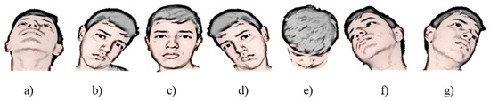
Figure 3.
Head movements in seven directions to operate the prototype [45]: (a) Backward movement; (b) left movement; (c) stop; (d) right movement; (e) forward movement; (f) right-back movement; (g) left-back movement.
3.3. Data Transfer Method from Prototype to Computer
The prototype instrumentation processes information using a data vector separated by commas. This vector has data of three ultrasonics sensors, Euler angles of the inertial motion sensor (two angles are taken, since the third angle allows free mobility of the user without activating the prototype), temperature (parameter to know the status of the prototype), and optical encoder. The vector structure is shown in Figure 4. Data are processed by PythonTM, a high-level programming language.

Figure 4.
Vector structure of data reception that sends the prototype.
The flowchart for sending and receiving data between the computer and prototype is shown in Figure 5. Libraries importation allows to declare variables and constants, share data between threads, and start the communication to send information.
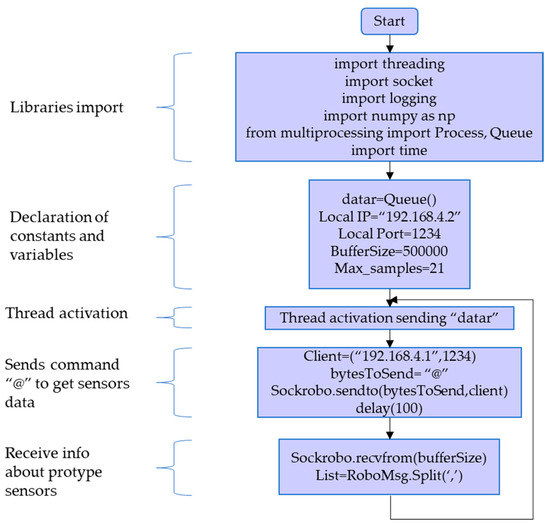
Figure 5.
Flowchart of sending and receiving data between computer and prototype.
4. Results
This section is divided in three parts: First, the mathematical model based on physical characteristics of the prototype; second, the manual controller operated by graphical interface; and third, automatic controllers that uses fuzzy logic techniques.
4.1. Mathematical Model of the Prototype
The mathematical model developed here takes into account the electromechanical model of the DC motor connected to the load. In this case, the load is a closed rack pinion system. This system has its own characteristics related to the equivalent inertia present in two wheels, which are connected using track links and a static axle, as shown in Figure 6.
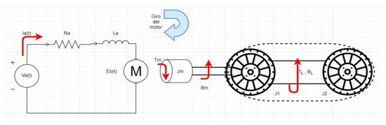
Figure 6.
Graphic representation of the dynamic model of the wheelchair prototype.
The model of the Figure 6 is described applying equations, where Equation (1) represents the voltage in the electrical circuit of the DC motors. Equation (2) relates the torque in the motor and the equivalent inertia of the track wheels. Equation (3) associates the armature current and torque in the motor. Finally, Equation (4) relates voltage motor to angular velocity motor.
Equivalent inertia is represented as:
Replacing in Equation (2), the equation is:
The inertia of the wheel 1 is the same as the inertia of the wheel 2, and for that reason, it will be called “Jo”, representing two inertias. Therefore, the equations of the second order system are:
The state space representation of the system is:
The mathematical model theory developed in this research allows knowing the dynamic of the system in order to establish parameters of position, speed, and orientation of the fuzzy controllers, besides recognizing dynamic characteristics of the controllers to make comparisons between classic and intelligent control.
4.2. Manual Control
Manual control was carried out considering the instrumentation of the system by sending commands (see Table 1) to drive the prototype. In addition, a graphical interface was designed to interact with the user through buttons and a speed setting. The main window is shown in Figure 7a, where the user can manually operate the system with buttons. Figure 7b shows the window that is generated when the user clicks an automatic controller button of the main window (left buttons).
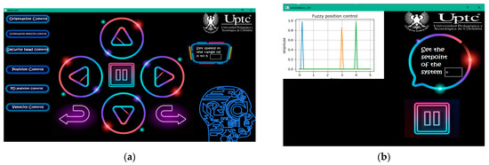
Figure 7.
Graphical interface designed in Qt Creator: (a) Main window of the application; (b) new window displayed after clicking the automatic controller buttons.
4.3. Automatic Control
The automatic control of this research is based on intelligent control techniques. Then, the position, speed, and orientation control using fuzzy logic is developed.
4.3.1. Fuzzy Position Control
Position control establishes a reference, which is determined by the user depending on nearby obstacles located in front of the prototype. The block diagram of the fuzzy position controller is shown in Figure 8, in which there is a physical input called distance, and an output named system position.
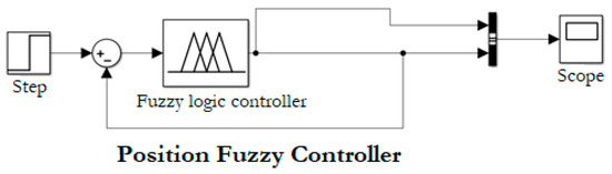
Figure 8.
Block diagram of position fuzzy controller designed in “Simulink” of MATLAB®.
Linguistic variables allow establishing ranges in which the error will be in the desired range. The input variables are: “Big Negative Error” (BNE), when the difference between setpoint and measured value by the ultrasonic module is negative; “Big Positive Error” (BPE), when the difference is positive; and “Zero Error” (ZE), when the error equals to zero. The output variables to send commands to the prototype are “forward” (forw), “Stop” (stop), and “Come back” (back). In Figure 9a, the error established in the discourse universe is exposed. This value changes with the user input using the graphical interface. In Figure 9b, the output observed corresponds to speed commands sent to the prototype.
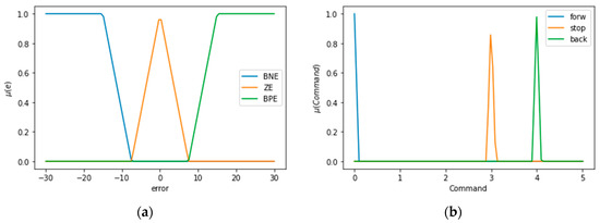
Figure 9.
Linguistic variables for the error and controller output made in Google Colab: (a) linguistic variables of position error; (b) linguistic variables of output controller.
Figure 10 shows the simulation of fuzzy rules and control surface using “FuzzyLogicDesigner” by MATLAB®. Table 2 shows the fuzzy rules table based on linguistic variables.
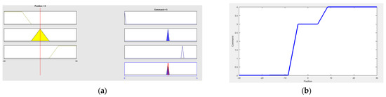
Figure 10.
Position fuzzy control simulation using “FuzzyLogicDesigner” by MATLAB®: (a) Output fuzzy rules simulation; (b) Control surface.
Table 2.
Fuzzy rules based on linguistic variables for position controller.
The fuzzification process is carried out employing membership functions in which the user enters a value, and the membership error is found in each fuzzy input set, obtaining the membership value. The defuzzification is implemented based on the centroid method, which takes the fuzzy output function and finds the central value of this function.
4.3.2. Fuzzy Speed Control
Fuzzy speed control is executed utilizing a speed measure sent via optical encoder. The controller generates an output in revolutions per minute (rpm), which is measured within speed ranges stablished in Table 1. The ranges are related to speed commands and rpm on Table 3.
Table 3.
Speed ranges in RPM and speed commands relationship.
Based on Table 3, the speed is parameterized for the fuzzy velocity control with respect to output controller command. The block diagram of the fuzzy speed controller has the same structure of the fuzzy position controller because both have one input and one output. The input error functions are shown in Figure 11a, which are: “Big Negative (BN), “Medium Negative” (MN), “Small Negative” (SN), “Small Positive” (SP), “Medium Positive” (MP), and “Big Positive” (BP). The output variables are observed in Figure 11b: “Small Increase” (SI), “Medium Increase” (MI), “Total Increase” (TI), “Small Decrease” (SD), “Medium Decrease” (MD), and “Total Decrease” (TD). The speed control simulated the cruising speed of cars.
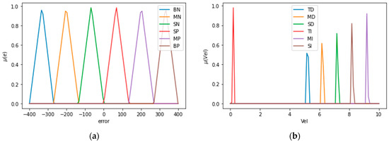
Figure 11.
Linguistic variables for input error and output speed controller made in Google Colab: (a) Linguistic variables of speed input error; (b) linguistic variables of output speed controller.
Table 4 shows fuzzy rules. The response time of the controller was 335 ms.
Table 4.
Fuzzy rules based on linguistic variables for speed controller.
4.3.3. Fuzzy Orientation Controller with Constant Speed
Fuzzy orientation control uses IMOCAP-GIS system. The instrumentation of the motion capture system located in the cap allows sending Euler angles (pitch and roll), which are the input of the fuzzy controller. The block diagram of the controller is shown in Figure 12 from a MATLAB® simulation.
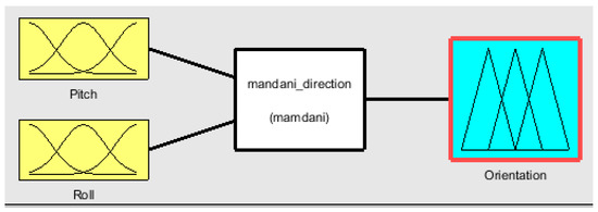
Figure 12.
Block diagram for the fuzzy orientation controller.
Figure 13a shows the membership functions for pitch angle. Figure 13b shows the membership functions for roll angle. Figure 13c describes the output membership functions, which is the prototype orientation.
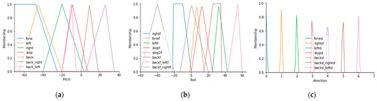
Figure 13.
Membership functions for the inputs and outputs of the fuzzy orientation controller with constant speed: (a) Membership functions for pitch angle; (b) membership functions for roll angle; (c) membership functions for the output controller.
In this case, the conditionals use the structure: “IF …. AND…THEN…”. Figure 14 shows the fuzzy rules construction, inputs and outputs display, and the control orientation surface.
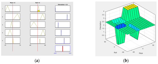
Figure 14.
Fuzzy controller configuration employing “FuzzyLogicDesigner” by MATLAB®: (a) Fuzzy rules graphic; (b) control surface.
4.3.4. Fuzzy Orientation Controller with Variable Speed
Fuzzy orientation controller with variable speed uses membership functions for three operating speeds taking into account head tilt angles. Figure 15a exhibits the functions for pitch angle. Figure 15b shows roll angle functions. Figure 15c shows the output controller where the system has three velocities for each direction: Forward, left, right, and back. The directions left-back and right-back run at full speed.
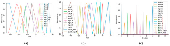
Figure 15.
Membership functions for inputs and output of the orientation controller with variable speed: (a) Membership functions for the pitch angle; (b) membership functions for the roll angle; (c) membership functions for the output controller.
Table 5 shows the set of measurements of the tilt head angles for the orientation controller.
Table 5.
Roll and Pitch angles for head orientation.
4.3.5. Safety Control
The orientation control that was developed in the last section uses ultrasonic sensors to avoid nearby obstacles. The controller was implemented using conditionals in the code. Safety ranges are defined depending on the prototype location and considering the sensor measurements. Figure 16 shows a route inside a room with walls as obstacles. The algorithm is written when the prototype runs clockwise and counterclockwise. Two static obstacles were placed in the center of the route, representing areas in which the prototype can only be driven forward or backwards.
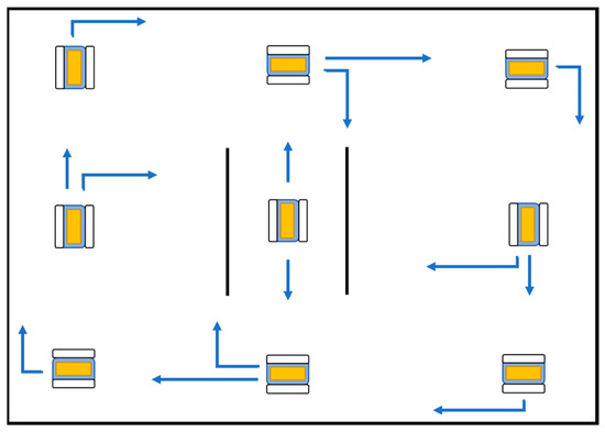
Figure 16.
Room route with static obstacles.
5. Discussion
The developed system has two aspects to be commented in this section. First, the performance of the electronic controllers based on system validation and compliance with design specifications. Second, user experience in terms of level of satisfaction with the system and recommendations.
5.1. Electronic System Response
The discussion in this section addresses details of the position, speed, and orientation controller designed here. The system has several elements in common with the research developed by Fall and Latour [33], such as communication systems through a WiFi module, whereas the graphical interface has similitudes with the works developed by Ruzaij et al. [8,29,30,31].
Marins et al. [34] developed data processing utilizing Arduino. In this case, the microcontroller was programmed using Teensy®, which is compatible with Arduino libraries. Emergency buttons were implemented in the system to disable controllers. On the other hand, distance sensors were used to ensure user safety, such as suggested by Prasad et al. [35].
The system used inertial sensors and distance sensors to be operated by the user of the prototype wheelchair; however, the ultrasonic range modules used in the system can be replaced by laser sensors to improve the accuracy of the measurements. On the other hand, the validation method of electronic controllers was analyzed using closed circuits that evaluate dynamic characteristics of the prototype. The inertial system was used due to its adaptability with the user, specifically users with disabilities in their lower and upper limbs.
It is worth commenting that although other systems used eye movements or brain signals to command a wheelchair, such as in [46,47], respectively, their response time is longer (about 2 s) compared to the system developed here (average of 100 ms). For instance, the route described by Gomes et al. [47] indicated a time lapse with an average of 1.56 s. In this research, the time used to make the route (shown in Table 7) had a variation between 22 and 62 s, with a distance of 10 m.
5.1.1. Position Control
The stability of the systems is verified by the adequate operation of the controllers and satisfied design features, and the response time depends on parallelism used for sending and receiving data. The response time of the position controller was 225 ms, which was not possible to compare with results from the literature, as the authors of the literature reviewed did not quantitatively described the execution time of their controllers.
Njah and Jallouli [48] developed a fuzzy controller employing ultrasonic sensors with the aim of detecting obstacles. However, the response time of their system is unknown, and a specific environment is shown with randomly located obstacles.
Cui et al. [49] developed a fuzzy position system; however, their structure is different compared with this research, as their device operation is autonomous, meaning that it does not require user interaction at all, and involves angular variations when nearby obstacles are detected [49].
5.1.2. Orientation Control
The response time of the orientation controllers is shown in Table 6. The fuzzy controller has a lower response time than the classic controller. The temporal response of the system was made using temporal measurement for each loop.
Table 6.
Response time of orientation controllers designed.
Saruchi et al. [50] developed a fuzzy orientation controller to drive their prototype, which has linguistic variables related to the input error and output error. In contrast, this research has Euler angles as inputs of the system and direction as output.
Yang et al. [51] designed a wheelchair control that also has Euler angles as inputs sent by a motion sensor, and their system outputs are directions of the wheelchair. However, their system has a test protocol to recognize motor intention of the user, calculating a recognition rate. In this research, the system is evaluated with user experience and response time of the controllers. The controller validation was carried out with a person with null mobility in lower limbs as shown in Figure 17.
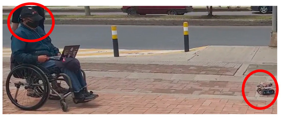
Figure 17.
Validation test for the fuzzy variable speed orientation controller.
5.2. User Satisfaction with the Developed System
A route circuit was designed and carried out by 10 participants using the prototype with orientation controllers at constant and variable speed. The circuit was realized four times by each user to analyze the system performance, obstacle detection, and user experience. Figure 18 shows the four routes made by User 1. The first two routes were used for the system understanding and its interface. It was observed that in the latest tests, the user demonstrated a better control of the system executing movements.
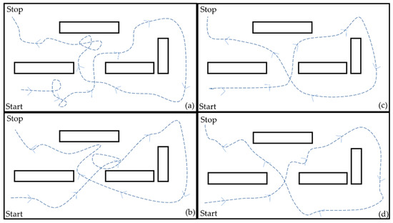
Figure 18.
Routes carried out by User 1: (a) Route 1; (b) Route 2; (c) Route 3; (d) Route 4.
Table 7 shows the execution time of the routes for the three controllers: Manual control, orientation controller with constant speed, and orientation controller with variable speed, obtaining different results in each case.
Table 7.
Response time of controllers in each participant.
Figure 19 shows the users manipulating the system with manual control and head movement function.
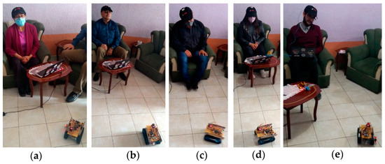
Figure 19.
Participants utilizing orientation control: (a) Stop command (central head position); (b) backward command; (c) right command; (d) forward command; (e) left command.
To measure the system usability, the literature describes different methodologies that analyzes the user experiences, such as the System Usability Scale (SUS) [43], that was used in this research. The SUS qualitative ranges are: From 0 to 25, worse; from 25 to 50, poor; between 50 and 70, good; from 70 to 80, very good; between 80 and 90, excellent; and greater than 90, unmatched. The users answered 10 questions, and each one was analyzed using an algorithm established for this measurement. The mean of the scores represents the SUS rate. The results of the survey are shown in Table 8. The statements are:
- I think that I would like to use this feature frequently.
- I found the feature unnecessarily complex.
- I thought the feature was easy to use.
- I think that I would need the support of a technical person to be able to use this feature.
- I found the various functions in this feature were well integrated.
- I thought there was too much inconsistency in this feature.
- I would imagine that most people would learn to use this feature very quickly.
- I found the feature very cumbersome to use.
- I felt very confident using the feature.
Table 8.
Application of System Usability Scale in participants.
Table 8.
Application of System Usability Scale in participants.
| User | Q1 | Q2 | Q3 | Q4 | Q5 | Q6 | Q7 | Q8 | Q9 | Q10 | Total |
|---|---|---|---|---|---|---|---|---|---|---|---|
| 1 | 4 | 2 | 4 | 2 | 3 | 4 | 5 | 1 | 4 | 2 | 72.5 |
| 2 | 4 | 3 | 5 | 2 | 5 | 4 | 5 | 1 | 4 | 1 | 80 |
| 3 | 5 | 2 | 5 | 3 | 4 | 4 | 5 | 1 | 4 | 3 | 72.5 |
| 4 | 5 | 1 | 5 | 4 | 5 | 1 | 5 | 1 | 5 | 1 | 90 |
| 5 | 3 | 1 | 5 | 2 | 5 | 1 | 5 | 1 | 2 | 1 | 85 |
| 6 | 4 | 4 | 5 | 3 | 5 | 3 | 5 | 1 | 4 | 2 | 75 |
| 7 | 4 | 2 | 5 | 2 | 4 | 2 | 5 | 1 | 2 | 2 | 77.5 |
| 8 | 3 | 4 | 5 | 2 | 4 | 3 | 3 | 1 | 3 | 2 | 65 |
| 9 | 5 | 1 | 5 | 4 | 4 | 2 | 5 | 1 | 3 | 2 | 80 |
| 10 | 5 | 2 | 5 | 2 | 5 | 4 | 5 | 1 | 4 | 2 | 82.5 |
I needed to learn a lot of things before I could get going with this feature.
The results indicate that the SUS rates the system as “very good”, obtaining a mean score of 78. The system is accepted because the results are above 70. This qualitative rating was obtained from the analysis of the responses of all users, and taking into account the rating scale for the data provided by the questionnaire. In comparison, another study [52] implemented a SUS for rating a controller system of a wheelchair that incorporates a virtual hand to reach objects, and obtained a score of 65.3, which represents a qualitative rating of “good”. Despite having different instrumentation system and control, the scoring method is the same for both.
On the other hand, Montesano et al. [53] carried out an evaluation based on two perspectives: First, performance of the system and second, user experience. The system usability was evaluated quantitatively with four participants, unlike this research, conducted with 10 participants. Lastly, Onyango et al. [54] validated the prototype implementing an evaluation system that differs of the used in this research. The system had static obstacles and they evaluated the system safety when avoiding obstacles, such as in this research.
It is worth mentioning that in our experiments, the users referred to the system as “very good”, mentioning the importance of the manual controls to operate the prototype. The speed control option with constant speed allowed the users to drive long distances without manipulating the interface, making the prototype more autonomous. On the other hand, the orientation control developed here allowed the users to have control over the prototype without using their upper or lower limbs. The users mentioned that it is essential to have distance sensors activated all the time, as well as a safety control to avoid obstacles or accidents.
6. Conclusions
A position, speed, and orientation control system that implements head movements using a graphical interface was developed here. The position controller obtained a response time of 225 ms, and the speed control simulated the cruising speed of cars. The fuzzy orientation controllers responded in less time than on/off control, allowing the prototype to run in seven directions based on head movements. The participants had a high user experience, rating the system as “very good”, with a score of 78 out of 100 possible points. One test included the participation of a person with physical disability.
The users highlighted the use of distance sensors to detect nearby obstacles as a safety measure. However, the system cannot be used for long periods of time, as it can generate tiredness by the execution of several head movements. It is worth noting that our system can be used both by means of manual control (using the graphical interface) or processing head movements and tilt angles. The manual control was developed to be used by people with zero mobility in lower limbs whereas the processing of head movements is adequate to be used by people with zero mobility in lower and upper limbs.
The contribution of our system to the state of the art is based on the electronic development, executing the system in real time, and allowing setting parameters to be taken into account to validate it in a physical wheelchair.
Author Contributions
Conceptualization, M.C.-C. and A.X.G.-C.; methodology, M.C.-C. and A.X.G.-C.; software, A.X.G.-C.; validation, M.C.-C., A.X.G.-C., and T.B.-F.; formal analysis, M.C.-C. and A.X.G.-C.; investigation, M.C.-C., A.X.G.-C., and T.B.-F.; resources, M.C.-C.; data curation, M.C.-C., A.X.G.-C., and T.B.-F.; writing—original draft preparation, M.C.-C. and A.X.G.-C.; writing—review and editing: M.C.-C., A.X.G.-C., and T.B.-F.; visualization, A.X.G.-C.; supervision, M.C.-C., A.X.G.-C., and T.B.-F.; project administration, M.C.-C.; funding acquisition, M.C.-C. All authors have read and agreed to the published version of the manuscript.
Funding
This study was funded by Universidad Pedagógica y Tecnológica de Colombia (project number SGI 2657) and the APC was funded by the same institution.
Institutional Review Board Statement
The study was conducted according to the guidelines of the Declaration of Helsinki, and approved by the Ethics Committee of Universidad Pedagógica Y Tecnológica De Colombia in the context of announcement 4 of 2019, of the SGI 2657 project, which began on 23 May 2019.
Informed Consent Statement
Informed consent was obtained from all subjects involved in the study.
Data Availability Statement
Informed consent of the participants are available writing to: aura.gonzalez@uptc.edu.co.
Acknowledgments
This work was supported by the Software Research Group GIS from the School of Computer Science, Engineering Department, Universidad Pedagógica y Tecnológica de Colombia (UPTC).
Conflicts of Interest
The authors declare no conflict of interest.
References
- World Health Organization. World Report on Disability. Available online: https://www.who.int/disabilities/world_report/2011/report.pdf (accessed on 17 April 2021).
- Ganz, F.; Hammam, N.; Pritchard, L. Sedentary behavior and children with physical disabilities: A scoping review. Disabil. Rehabil. 2020, 1–13. [Google Scholar] [CrossRef] [PubMed]
- Sol, M.E.; Verschuren, O.; de Groot, L.; de Groot, J.F. Development of a wheelchair mobility skills test for children and adolescents: Combining evidence with clinical expertise. BMC Pediatr. 2017, 17, 1–18. [Google Scholar] [CrossRef] [PubMed][Green Version]
- Wai, E.K.; Owen, J.; Fehlings, D.; Wright, J.G. Assessing Physical Disability in Children with Spina Bifida and Scoliosis. J. Pediatr. Orthop. 2000, 20, 765–770. [Google Scholar] [CrossRef] [PubMed]
- Busby, A.; Abramsky, L.; Dolk, H.; Armstrong, B.; Addor, M.-C.; Anneren, G.; Armstrong, N.; Baguette, A.; Barisic, I.; Berghold, A.; et al. Preventing neural tube defects in Europe: A missed opportunity. Reprod. Toxicol. 2005, 20, 393–402. [Google Scholar] [CrossRef] [PubMed]
- World Health Organization. Disability and Health. Available online: https://www.who.int/news-room/fact-sheets/detail/disability-and-health (accessed on 3 January 2021).
- Jang, W.A.; Lee, S.M.; Lee, D.H. Development BCI for individuals with severely disability using EMOTIV EEG headset and robot. In Proceedings of the 2014 International Winter Workshop on Brain-Computer Interface (BCI), Gangwon, Korea, 17–19 February 2014; IEEE: Piscataway, NJ, USA, 2014; pp. 1–3. [Google Scholar]
- Ruzaij, M.F.; Neubert, S.; Stoll, N.; Thurov, K. Auto Calibrated Head Orientation Controller for Robotic-Wheelchair Using MEMS Sensors and Embedded Technologies. In Proceedings of the Sensors Application Symposium (SAS 2016), Catania, Italy, 20–22 April 2016; pp. 433–438. [Google Scholar]
- Kader, M.A.; Alam, M.E.; Jahan, N.; Bhuiyan, A.B.; Alam, M.S.; Sultana, Z. Design and implementation of a head motion- controlled semi-autonomous wheelchair for quadriplegic patients based on 3-axis accelerometer. In Proceedings of the 2019 22nd International Conference on Computer and Information Technology (ICCIT 2019), Dhaka, Bangladesh, 18–20 December 2019; pp. 1–6. [Google Scholar]
- Rohmer, E.; Pinheiro, P.; Cardozo, E.; Bellone, M.; Reina, G. Laser based Driving Assistance for Smart Robotic Wheelchairs. In Proceedings of the 2015 IEEE 20th Conference on Emerging Technologies & Factory Automation (ETFA), Luxembourg, 8–11 September 2015; pp. 1–4. [Google Scholar]
- Chocoteco, J.; Morales, R.; Feliu, V.; Sánchez, L. Trajectory Planning for a Stair-Climbing Mobility System Using Laser Distance Sensors. IEEE Syst. J. 2016, 10, 944–956. [Google Scholar] [CrossRef]
- Kim, K.T.; Lee, S.W. Steady-state somatosensory evoked potentials for brain-controlled wheelchair. In Proceedings of the 2014 International Winter Workshop on Brain-Computer Interface (BCI), Gangwon, Korea, 17–19 February 2014. [Google Scholar]
- Turnip, A.; Hidayat, T.; Kusumandari, D.E. Development of brain-controlled wheelchair supported by raspicam image processing based Raspberry pi. In Proceedings of the 2017 2nd Conference on Automation, Cognitive Science, Optics, Micro Electro-Mechanical System and Information Technology (ICACOMIT), Jakarta, Indonesia, 23–24 October 2017; pp. 7–11. [Google Scholar]
- Borges, L.R.; Martins, F.R.; Naves, E.L.; Bastos, T.F.; Lucena, V.F. Multimodal System for Training at Distance in a Virtual or Augmented Reality. In Proceedings of the 4th IFAC Symposium on Telematics Applications TA 2016, Porto Alegre, Brazil, 6–9 November 2016; pp. 156–160. [Google Scholar]
- Lu, T. A motion control method of intelligent wheelchair based on hand gesture recognition. In Proceedings of the IEEE 8th conference on Industrial Electronics and Applications (ICIEA), Melbourne, Australia, 19–21 June 2013; pp. 957–962. [Google Scholar]
- Postolache, O.; Viegas, V.; Dias, J.M.; Vinhas, D.; Silva, P.; Postolache, G. Toward developing a smart wheelchair for user physiological stress and physical activity monitoring. In Proceedings of the 2014 IEEE International Symposium on Medical Measurements and Applications (MeMeA), Lisbon, Portugal, 11–12 June 2014; pp. 1–6. [Google Scholar]
- Dobrea, M.C.; Dobrea, D.M.; Severin, I.C. A new wearable system for head gesture recognition designed to control an intelligent wheelchair. In Proceedings of the 2019 E.Health and Bioengineering Conference (EHB), Iasi, Romania, 21–23 November 2019; pp. 1–5. [Google Scholar]
- Jang, G.; Choi, Y. EMG-based continuous control method for electric wheelchair. In Proceedings of the 2014 IEEE/RSJ International Conference on Intelligent Robots and Systems, Chicago, IL, USA, 14–18 September 2014; pp. 3549–3554. [Google Scholar]
- Küçükyildiz, G.; Ocak, H.; Şayli, Ö.; Karakaya, S. Real time control of a wheelchair based on EMG and Kinect for the disabled people. In Proceedings of the 2015 Medical Technologies National Conference (TIPTEKNO), Bodrum, Turkey, 15–18 October 2015; pp. 1–4. [Google Scholar]
- Fortune, E.; Cloud-Biebl, B.A.; Madansingh, S.I.; Ngufor, C.G.; Van Straaten, M.G.; Goodwin, B.M.; Murphree, D.H.; Zhao, K.D.; Morrow, M.M. Estimation of manual wheelchair-based activities in the free-living environment using a neural network model with inertial body-worn sensors. J. Electromyogr. Kinesiol. 2019, 102337. [Google Scholar] [CrossRef] [PubMed]
- Taniue, H.; Kaneko, J.; Kojima, K. Development of automatic barrier detection system for wheelchair. In Proceedings of the 2015 IEEE 4th Global Conference on Consumer Electronics (GCCE), Osaka, Japan, 27–30 October 2015; pp. 374–376. [Google Scholar]
- Lee, Y.T.; Chiu, C.S.; Kuo, I.T. Fuzzy wall-following control of a wheelchair. In Proceedings of the 2017 Joint 17th World Congress of International Fuzzy Systems Association and 9th International Conference on Soft Computing and Intelligent Systems (IFSA-SCIS), Otsu, Japan, 27–30 June 2017; pp. 1–6. [Google Scholar]
- Maatoug, K.; Njah, M.; Jalloulli, M. Multisensor data fusion for electrical wheelchair localization using extended Kalman Filter. In Proceedings of the 2017 18th International Conference on Sciences and Techniques of Automatic Control and Computer Engineering (STA), Monastir, Tunisia, 21–23 December 2017; pp. 257–260. [Google Scholar]
- Zhao, J.; Huang, X.; Massoud, Y. An efficient real-time FPGA implementation for object detection. In Proceedings of the 2014 IEEE 12th International New Circuits and Systems Conference (NEWCAS), Trois-Rivieres, QC, Canada, 22–25 June 2014; pp. 313–316. [Google Scholar]
- Wu, B.F.; Jen, C.L.; Tsou, T.Y.; Chen, P.Y. Accompanist recognition and tracking for intelligent wheelchairs. In Proceedings of the 2014 IEEE International Conference on Systems, Man and Cybernetics (SMC), San Diego, CA, USA, 5–8 October 2014; pp. 2138–2143. [Google Scholar]
- Manta, L.; Cojocaru, D.; Vladu, I.; Dragomir, A.; Marin, A. Wheelchair control by head motion using a noncontact method in relation to the pacient. In Proceedings of the 2019 20th International Carpathian Control Conference (ICCC), Krakow-Wieliczka, Poland, 26–29 May 2019; pp. 1–6. [Google Scholar]
- Callejas, M.; González, A.X.; Bastos, T.F. Control systems and electronic instrumentation applied to autonomy in wheelchair mobility: The state of the art. Sensors 2020, 20, 6326. [Google Scholar] [CrossRef] [PubMed]
- Bastos, T.F.; Dinesh, K.; Arjunan, S. Devices for Mobility and Manipulation for People with Reduced Abilities, 1st ed.; CRC Press: Boca Raton, FL, USA, 2014; pp. 1–232. ISBN 9780429102714. [Google Scholar]
- Ruzaij, M.F.; Neubert, S.; Stoll, N.; Thurov, K. Design and implementation of low-cost intelligent wheelchair controller for quadriplegias and paralysis patient. In Proceedings of the 2017 IEEE 15th International Symposium on Applied Machine Intelligence and Informatics (SAMI), Herl’any, Slovakia, 26–28 January 2017; pp. 000399–000404. [Google Scholar]
- Ruzaij, M.F.; Neubert, S.; Stoll, N.; Thurov, K. A speed compensation algorithm for a head tilts controller used for wheelchairs and rehabilitation applications. In Proceedings of the 2017 IEEE 15th International Symposium on Applied Machine Intelligence and Informatics (SAMI), Herl’any, Slovakia, 26–28 January 2017; pp. 000497–000502. [Google Scholar]
- Ruzaij, M.F.; Neubert, S.; Stoll, N.; Thurov, K. Multi-sensor Robotic-wheelchair controller for Handicap and Quadriplegia patients using embedded technologies. In Proceedings of the 2016 9th International Conference on Human System Interactions (HSI), Portsmouth, UK, 6–8 July 2016; pp. 103–109. [Google Scholar]
- Nasif, S.; Khan, M.A.G. Wireless head gesture-controlled wheel chair for disable persons. In Proceedings of the 2017 IEEE Region 10 Humanitarian Technology Conference (R10-HTC), Dhaka, Bangladesh, 21–23 December 2017; pp. 156–161. [Google Scholar]
- Fall, C.L.; Quevillon, F.; Blouin, M.; Latour, S.; Campeau-Lecours, A.; Gosselin, C.; Gosselin, B. A Multimodal Adaptive Wireless Control Interface for People with Upper-Body Disabilities. IEEE Trans. Biomed. Circuits Syst. 2018, 12, 564–575. [Google Scholar] [CrossRef] [PubMed]
- Marins, G.; Carvalho, D.; Marcato, A.; Junior, I. Development of a control system for electric wheelchairs based on head movements. In Proceedings of the 2017 Intelligent Systems Conference (IntelliSys), London, UK, 7–8 September 2017; pp. 996–1001. [Google Scholar]
- Prasad, S.; Sakpal, D.; Rakhe, P.; Rawool, S. Head-motion controlled wheelchair. In Proceedings of the 2017 2nd IEEE International Conference on Recent Trends in Electronics, Information & Communication Technology (RTEICT), Bangalore, India, 19–20 May 2017; pp. 1636–1640. [Google Scholar]
- Errico, V.; Ricci, M.; Palloti, A.; Giannini, F.; Saggio, G. Ambient assisted living for tetraplegic people by means of an electronic system based on a novel sensory headwear: Increased possibilities for reduced abilities. In Proceedings of the 2018 IEEE International Symposium on Medical Measurements and Applications (MeMeA), Rome, Italy, 11–13 June 2018; pp. 1–6. [Google Scholar]
- Dey, P.; Hasan, M.M.; Mostofa, S.; Rana, A.I. Smart wheelchair integrating head gesture navigation. In Proceedings of the 2019 International Conference on Robotics, Electrical and Signal Processing Techniques (ICREST), Dhaka, Bangladesh, 10–12 June 2019; pp. 329–334. [Google Scholar]
- Ayman, A.; Attalah, O.; Shaban, H. Smart system for recognizing daily human activities based on wrist IMU sensors. In Proceedings of the 2019 International Conference on Advances in the Emerging Computing Technologies (AECT), Al Madinah Al Munawwarah, Saudi Arabia, 10 February 2020; pp. 1–6. [Google Scholar]
- Philpott, L.; Weaver, S.; Gordon, D.; Conway, P.; West, A. Assessing wireless inertia measurement units for monitoring athletics sprint performance. Sensors 2014, 17, 2199–2202. [Google Scholar]
- Setiawan, A.; Muhammad, F.; Vincent Hidayat, A. Development of an web-based wearable gait recognition system using gyroscope and accelerometer sensors. In Proceedings of the 2020 International Seminar on Application for Technology of Information and Communication (iSemantic), Semarang, Indonesia, 19–20 September 2020; pp. 370–373. [Google Scholar]
- Gómez, A.; Espinosa, N.; Valdés, B. Foot-mounted inertial measurement units-based device for ankle rehabilitation. J. Appl. Sci. 2018, 8, 2032. [Google Scholar] [CrossRef]
- Gujarathi, T.; Bhole, K. Gait Analysis Using Imu Sensor. In Proceedings of the 2019 10th International Conference on Computing, Communication and Networking Technologies (ICCCNT), Kanpur, India, 6–8 July 2019; pp. 1–5. [Google Scholar]
- Callejas, M.; Gutierrez, R.M.; Hernandez, A.I. Joint amplitude MEMS based measurement platform for low cost and high accessibility telerehabilitation: Elbow case study. J. Bodyw. Mov. Ther. 2017, 21, 574–581. [Google Scholar] [CrossRef] [PubMed]
- Callejas, M.; Alvarez, J.C.; Alvarez, D. Capture and analysis of biomechanical signals with inertial and magnetic sensors as support in physical rehabilitation processes. In Proceedings of the 2016 IEEE 13th International Conference on Wearable and Implantable Body Sensor Networks (BSN), San Francisco, CA, USA, 14–17 June 2016; pp. 119–123. [Google Scholar]
- Callejas, M. (Universidad Pedagógica y Tecnológica de Colombia, Tunja, Colombia); Images Repository of the Software Research Group. Personal communication, 2021.
- Louis, C.S.; Jia, P.; Gan, J.; Hu, H.; Yuan, K. EMG-based Hands-Free Wheelchair Control with EOG. In Proceedings of the 2007 IEEE International Conference on Robotics and Biomimetics (ROBIO), Sanya, China, 15–18 December 2017; pp. 1266–1271. [Google Scholar]
- Gomes, D.; Fernandes, F.; Castro, E.; Pires, G. Head-movement interface for wheelchair driving based on inertial sensors. In Proceedings of the 2019 IEEE 6th Portuguese Meeting on Bioengineering (ENBENG), Lisbon, Portugal, 22–23 February 2019; pp. 1–4. [Google Scholar]
- Njah, M.; Jallouli, M. Wheelchair obstacle avoidance based on fuzzy controller and ultrasonic sensors. In Proceedings of the 2013 International Conference on computer Applications Technology (ICCAT), Sousse, Tunisia, 20–22 January 2013; pp. 1–5. [Google Scholar]
- Cui, S.; Su, X.; Zhao, L.; Bing, Z.; Yang, G. Study on Ultrasonic Obstacle Avoidance of Mobile Robot Based on Fuzzy Controller. In Proceedings of the 2010 International Conference on Computer Application and System Modeling (ICCASM), Taiyuan, China, 22–24 October 2010; pp. 233–237. [Google Scholar]
- Saruchi, S.; Ariff, M.H.; Zamzuri, H.; Amer, N.H.; Wahid, N.; Hassan, N.; Kadhir, Z.A. Lateral control strategy based on head movement responses for motion sickness mitigation in autonomous vehicle. J. Braz. Soc. Mech. Sci. Eng. 2020, 5, 223–237. [Google Scholar] [CrossRef]
- Yang, J.; Yu, C.; Wang, R.; Donghui, Z. A directional identification method based on position and posture of head for an omni-directional mobile wheelchair robot. In Proceedings of the International Conference on Intelligent Robotics and Applications (ICIRA), Wuhan, China, 16–18 August 2017; pp. 230–241. [Google Scholar]
- Morita, K.; Hiraki, T.; Matsukura, H.; Iwai, D.; Sato, K. Extension of Projection Area using Head Orientation in Projected Virtual Hand Interface for Wheelchair Users. In Proceedings of the 2020 59th Annual Conference of the Society of Instrument and Control Engineers of Japan (SICE), Chiang Mai, Thailand, 23–26 September 2020; pp. 421–426. [Google Scholar]
- Montesano, L.; Díaz, M.; Bhaskar, S.; Minguez, J. Towards an intelligent wheelchair system for users with cerebral palsy. IEEE Trans. Neural Syst. Rehabil. Eng. 2010, 18, 193–202. [Google Scholar] [CrossRef]
- Onyango, S.O.; Hamam, Y.; Djouani, K.; Daachi, B. Identification of wheelchair user steering behaviour within indoor environments. In Proceedings of the 2015 IEEE International Conference on Robotics and Biomimetics (ROBIO), Zhuhai, China, 6–9 December 2015; pp. 2283–2288. [Google Scholar]


Publisher’s Note: MDPI stays neutral with regard to jurisdictional claims in published maps and institutional affiliations. |
© 2021 by the authors. Licensee MDPI, Basel, Switzerland. This article is an open access article distributed under the terms and conditions of the Creative Commons Attribution (CC BY) license (https://creativecommons.org/licenses/by/4.0/).