
Application of Phase-Reversal Fresnel Zone Plates for High-Resolution Robotic Ultrasonic Non-Destructive Evaluation

 , , , and
Abstract
:1. Introduction
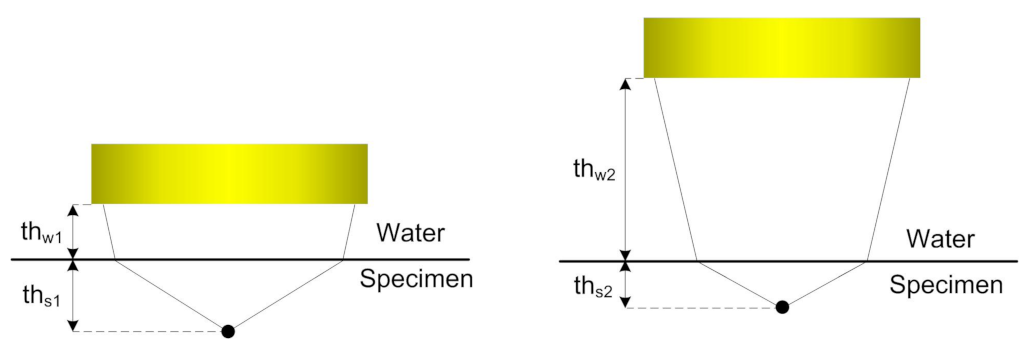
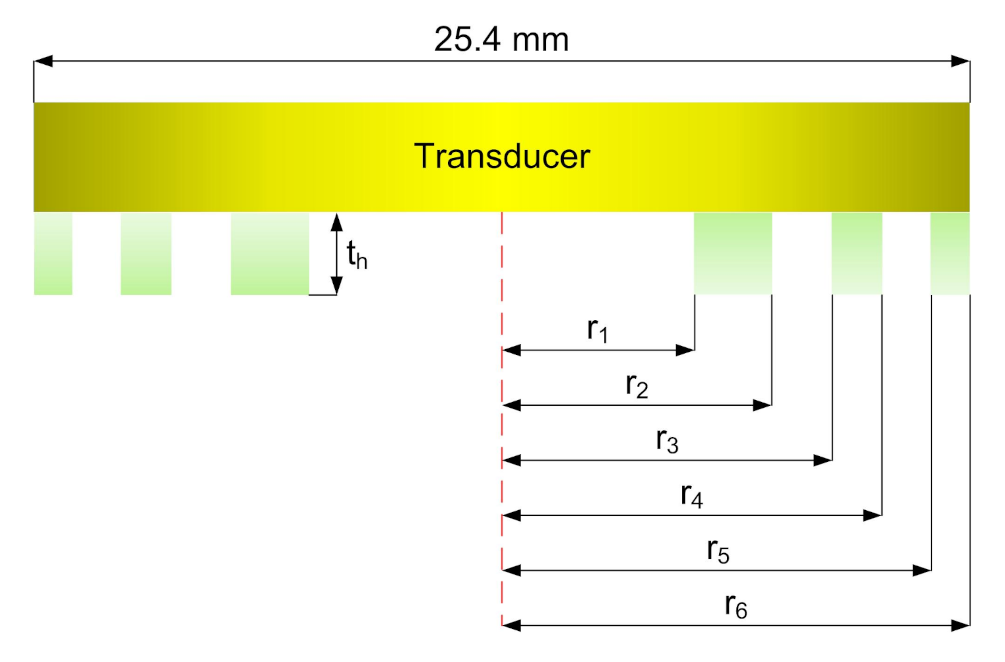
2. Theory and Determination of Design Parameters of the Lens
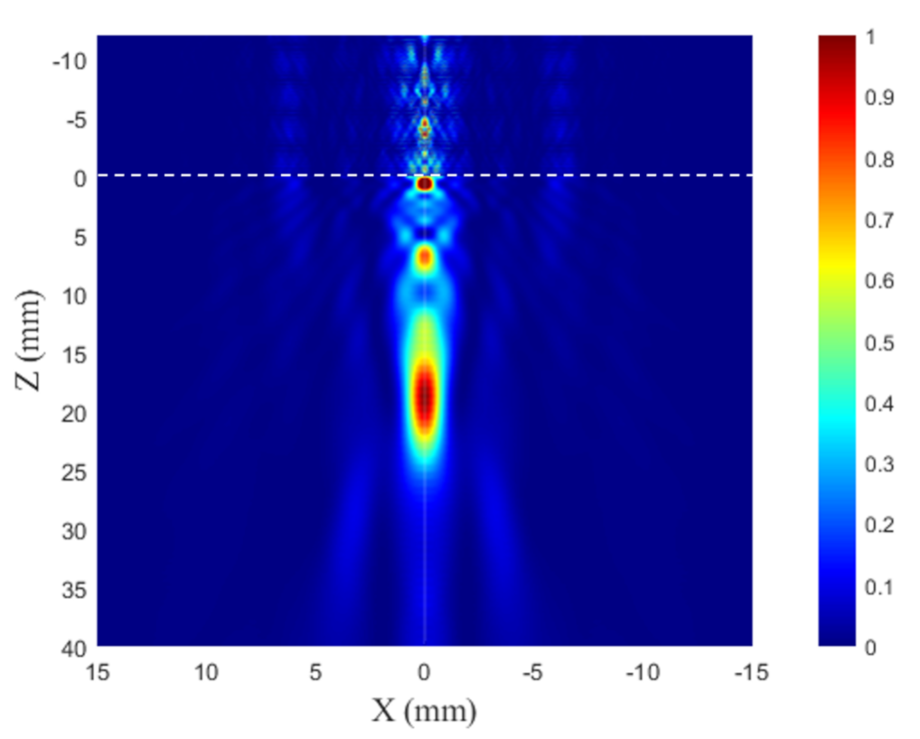
Lens Efficiency Verification through Numerical Model
3. Experimental Set-Up
4. Results and Discussion
5. Conclusions
Author Contributions
Funding
Institutional Review Board Statement
Informed Consent Statement
Data Availability Statement
Acknowledgments
Conflicts of Interest
References
- Cuevas, E.; Hernandez, S.; Cabellos, E. Robot-based solutions for NDT inspections: Integration of laser ultrasonics and air coupled ultrasounds for aeronautical components. In Proceedings of the 25th ASNT Research Symposium, New Orleans, LA, USA, 11–14 April 2016; pp. 39–46. [Google Scholar]
- Mineo, C.; Pierce, S.; Wright, B.; Cooper, I.; Nicholson, P. PAUT inspection of complex-shaped composite materials through six DOFs robotic manipulators. Insight-Non Test. Cond. Monit. 2015, 57, 161–166. [Google Scholar] [CrossRef] [Green Version]
- Acebes, M.; Bueno, R.G.; De, R.D.; Giacchetta, R. SITAU TRITON: High Speed Ultrasound Inspection System for Complex Geometry Composites. In Proceedings of the 10th International Symposium on NDT in Aerospace, Dresden, Germany, 24–26 October 2018. [Google Scholar]
- Mineo, C.; Herbert, D.; Morozov, M.; Pierce, S.; Nicholson, P.; Cooper, I. Robotic non-destructive inspection. In Proceedings of the 51st Annual Conference of the British Institute of Non-Destructive Testing, Northamptonshire, UK, 11–13 September 2012; pp. 345–352. [Google Scholar]
- Riise, J.; Mineo, C.; Pierce, S.G.; Nicholson, P.I.; Cooper, I. Adapting robot paths for automated NDT of complex structures using ultrasonic alignment. AIP Conf. Proc. 2019, 2102, 040006. [Google Scholar]
- Zhen, X.; Yong, Y.; Guang, X.C.; Guo, X.D.; Fang, L.F.; Liang, L.X. Profile tracking with ultrasonic alignment for automatic non-destructive testing of complex structures. Robot. Comput.-Integr. Manuf. 2018, 49, 134–142. [Google Scholar] [CrossRef]
- Xiao, Z.; Xu, C.; Xiao, D.; Liu, F.; Yin, M. An optimized robotic scanning scheme for ultrasonic NDT of complex structures. Exp. Tech. 2017, 41, 389–398. [Google Scholar] [CrossRef]
- Mineo, C.; Pierce, S.G.; Wright, B.; Nicholson, P.I.; Cooper, I. Robotic path planning for non-destructive testing of complex shaped surfaces. AIP Conf. Proc. 2015, 1650, 1977–1987. [Google Scholar]
- Mineo, C.; MacLeod, C.; Morozov, M.; Pierce, S.G.; Lardner, T.; Summan, R.; Powell, J.; McCubbin, P.; McCubbin, C.; Munro, G.; et al. Fast ultrasonic phased array inspection of complex geometries delivered through robotic manipulators and high speed data acquisition instrumentation. In Proceedings of the 2016 IEEE International Ultrasonics Symposium (IUS), Tours, France, 18–21 September 2016; pp. 1–4. [Google Scholar]
- Su, R.; Mineo, C.; MacLeod, C.N.; Pierce, S.G.; Gachagan, A. Multi-aperture beamforming for automated large structure inspection using ultrasonic phased arrays. AIP Conf. Proc. 2019, 2102, 100009. [Google Scholar]
- Fuentes, R.; Worden, K.; Antoniadou, I.; Mineo, C.; Pierce, S.; Cross, E.J. Compressive sensing for direct time of flight estimation in ultrasound-based NDT. In Proceedings of the 11th International Workshop on Structural Health Monitoring, Stanford, CA, USA, 12–14 September 2017. [Google Scholar]
- Mineo, C.; Summan, R.; Riise, J.; MacLeod, C.N.; Pierce, S.G. Introducing a new method for efficient visualization of complex shape 3D ultrasonic phased-array C-scans. In Proceedings of the 2017 IEEE International Ultrasonics Symposium (IUS), Washington, DC, USA, 6–9 September 2017; pp. 1–4. [Google Scholar]
- Mineo, C.; Riise, J.; Summan, R.; MacLeod, C.N.; Pierce, S.G. Index-based triangulation method for efficient generation of large three-dimensional ultrasonic C-scans. Insight-Non Test. Cond. Monit. 2018, 60, 183–189. [Google Scholar] [CrossRef] [Green Version]
- Hu, H.; Ye, C.; Wang, X.; Xu, N. Multi-angle spatial compound imaging in ultrasonic immersion testing using a single transducer. J. Instrum. 2018, 13, P07004. [Google Scholar] [CrossRef]
- Dolmatov, D.; Zhvyrblya, V.; Filippov, G.; Salchak, Y.; Sedanova, E. Advanced ultrasonic testing of complex shaped composite structures. IOP Conf. Ser. Mater. Sci. Eng. 2016, 135, 012010. [Google Scholar] [CrossRef] [Green Version]
- Stetson, J.T.; De Odorico, W. Robotic inspection of fiber reinforced composites using phased array UT. In AIP Conf. Proc. 2014, 1581, 1889–1895. [Google Scholar]
- Bulavinov, A.; Pinchuk, R.; Gurieva, T.; Lyanzberg, D.; Lider, A.; Demyanuk, D.; Sednev, D.; Zhvyrblya, V.; Filippov, G. Robot-based in-process examination of ITER dome and first-wall panels based on novel ultrasonic tomography approach. In Proceedings of the 19th World Conference on Non-Destructive Testing, Munich, Germany, 13–17 June 2016. [Google Scholar]
- Mohammadkhani, R.; Zanotti Fragonara, L.; Padiyar M, J.; Petrunin, I.; Raposo, J.; Tsourdos, A.; Gray, I. Improving depth resolution of ultrasonic phased array imaging to inspect aerospace composite structures. Sensors 2020, 20, 559. [Google Scholar] [CrossRef] [PubMed] [Green Version]
- Mineo, C.; MacLeod, C.; Su, R.; Lines, D.; Davì, S.; Cowan, B.; Pierce, S.G.; Paton, S.; Munro, G.; McCubbin, C.; et al. Robotic geometric and volumetric inspection of high value and large scale aircraft wings. In Proceedings of the 2019 IEEE 5th International Workshop on Metrology for AeroSpace (MetroAeroSpace), Turin, Italy, 19–21 June 2019; pp. 82–86. [Google Scholar]
- Pribanic, T.; McDaniel, D.; Musaramthota, V.; Zhou, X.; Zhou, J.; Cai, S. Effect of surface contamination on composite bond integrity and durability. In Proceedings of the 2012 Joint Advanced Materials Structures Center of Excellence 8th Annual Technical Meeting, Baltimore, MD, USA, 5 April 2012. [Google Scholar]
- Datla, N.; Papini, M.; Ulicny, J.; Carlson, B.; Spelt, J. The effects of test temperature and humidity on the mixed-mode fatigue behavior of a toughened adhesive aluminum joint. Eng. Fract. Mech. 2011, 78, 1125–1139. [Google Scholar] [CrossRef]
- Lozak, A.; Boller, C.; Bulavinov, A.; Pinchuk, R.; Kurz, J.; Sednev, D. Phase statistics and spectral analysis of ultrasonic signals for CFRP component assessment. In Proceedings of the EWSHM-7th European Workshop on Structural Health Monitoring, IFFSTTAR, Nantes, France, 8–11 July 2014. [Google Scholar]
- Olympus-IMS. RollerFORM Specifications. 2018. Available online: https://www.olympus-ims.com/en/rollerform/ (accessed on 18 November 2021).
- Tarrazó-Serrano, D.; Pérez-López, S.; Candelas, P.; Uris, A.; Rubio, C. Acoustic focusing enhancement in fresnel zone plate lenses. Sci. Rep. 2019, 9, 7067. [Google Scholar] [CrossRef] [PubMed] [Green Version]
- Xia, X.; Li, Y.; Cai, F.; Zhou, H.; Ma, T.; Zheng, H. Ultrasonic tunable focusing by a stretchable phase-reversal Fresnel zone plate. Appl. Phys. Lett. 2020, 117, 021904. [Google Scholar] [CrossRef]
- Calvo, D.C.; Thangawng, A.L.; Nicholas, M.; Layman, C.N. Thin Fresnel zone plate lenses for focusing underwater sound. Appl. Phys. Lett. 2015, 107, 014103. [Google Scholar] [CrossRef]
- Bazulin, E.; Rukhailo, N. Determination of the profile of the surface of a test object during automated nondestructive ultrasonic testing in the immersion mode and reconstruction of flaw images using the SAFT method. Russ. J. Nondestruct. Test. 2012, 48, 457–467. [Google Scholar] [CrossRef]
- Zhang, J.; Drinkwater, B.W.; Wilcox, P.D.; Hunter, A.J. Defect detection using ultrasonic arrays: The multi-mode total focusing method. NDT E Int. 2010, 43, 123–133. [Google Scholar] [CrossRef]
- Fan, C.; Caleap, M.; Pan, M.; Drinkwater, B.W. A comparison between ultrasonic array beamforming and super resolution imaging algorithms for non-destructive evaluation. Ultrasonics 2014, 54, 1842–1850. [Google Scholar] [CrossRef] [PubMed] [Green Version]


| Parameter | Value |
|---|---|
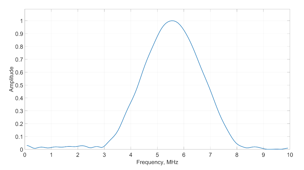
| The central frequency of ultrasonic transducer | 5.55 MHz |
| The diameter of ultrasonic transducer | 25.4 mm |
| Thickness of coupling media | 12 mm |
| Required depth of the focusing in testing specimen | 20 mm |
| Speed of longitudinal waves in testing object | 5900 m/s |
| Speed of longitudinal waves in coupling media | 1500 m/s |
| Speed of longitudinal waves in PR-FZP material | 2220 m/s |
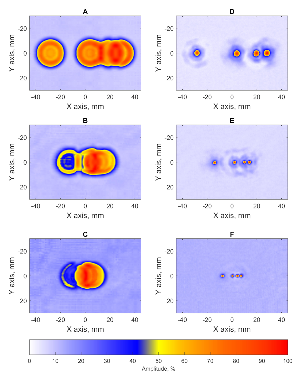
| Block | A | B | C |
|---|---|---|---|
| Diameter of FBH in the block (mm) | 5 | 3 | 2 |
| Estimated size of the flaw for the cases without PR-FZP application (mm) | 22.5 | 22 | 21.75 |
| SNR for the cases without PR-FZP application (dB) | 18.9 | 13.6 | 11.1 |
| Estimated size of the flaw for the cases with PR-FZP application (mm) | 5.13 | 3 | 1.87 |
| SNR for the cases with PR-FZP application (dB) | 26.6 | 20.7 | 17.6 |
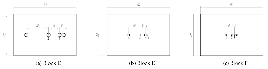
| Block | D | E | F | |||||||||
|---|---|---|---|---|---|---|---|---|---|---|---|---|
| FBH Diameter (mm) | 5 | 3 | 2 | |||||||||
| Defect number | 1 | 2 | 3 | 4 | 1 | 2 | 3 | 4 | 1 | 2 | 3 | 4 |
| FBH Size using PR-FZP (mm) | 5.1 | 5.2 | 5.1 | 5 | 3 | 3.1 | 3.1 | 3 | 1.9 | 1.9 | 1.9 | 2 |
| SNR using PR-FZP (dB) | 25.7 | 25.9 | 26.6 | 26 | 20.7 | 21 | 20.6 | 21.1 | 17.1 | 17.1 | 17.5 | 17.3 |
Publisher’s Note: MDPI stays neutral with regard to jurisdictional claims in published maps and institutional affiliations. |
© 2021 by the authors. Licensee MDPI, Basel, Switzerland. This article is an open access article distributed under the terms and conditions of the Creative Commons Attribution (CC BY) license (https://creativecommons.org/licenses/by/4.0/).
Share and Cite
Dolmatov, D.O.; Tarrazó-Serrano, D.; Filippov, G.A.; Uris, A.; Sednev, D.A. Application of Phase-Reversal Fresnel Zone Plates for High-Resolution Robotic Ultrasonic Non-Destructive Evaluation. Sensors 2021, 21, 7792. https://doi.org/10.3390/s21237792
Dolmatov DO, Tarrazó-Serrano D, Filippov GA, Uris A, Sednev DA. Application of Phase-Reversal Fresnel Zone Plates for High-Resolution Robotic Ultrasonic Non-Destructive Evaluation. Sensors. 2021; 21(23):7792. https://doi.org/10.3390/s21237792
Chicago/Turabian StyleDolmatov, Dmitry O., Daniel Tarrazó-Serrano, German A. Filippov, Antonio Uris, and Dmitry A. Sednev. 2021. "Application of Phase-Reversal Fresnel Zone Plates for High-Resolution Robotic Ultrasonic Non-Destructive Evaluation" Sensors 21, no. 23: 7792. https://doi.org/10.3390/s21237792
APA StyleDolmatov, D. O., Tarrazó-Serrano, D., Filippov, G. A., Uris, A., & Sednev, D. A. (2021). Application of Phase-Reversal Fresnel Zone Plates for High-Resolution Robotic Ultrasonic Non-Destructive Evaluation. Sensors, 21(23), 7792. https://doi.org/10.3390/s21237792