
Robustness and Tracking Performance Evaluation of PID Motion Control of 7 DoF Anthropomorphic Exoskeleton Robot Assisted Upper Limb Rehabilitation


Abstract
:1. Introduction
2. Smart Robotic Exoskeleton (SREx)
3. Kinematics of SREx
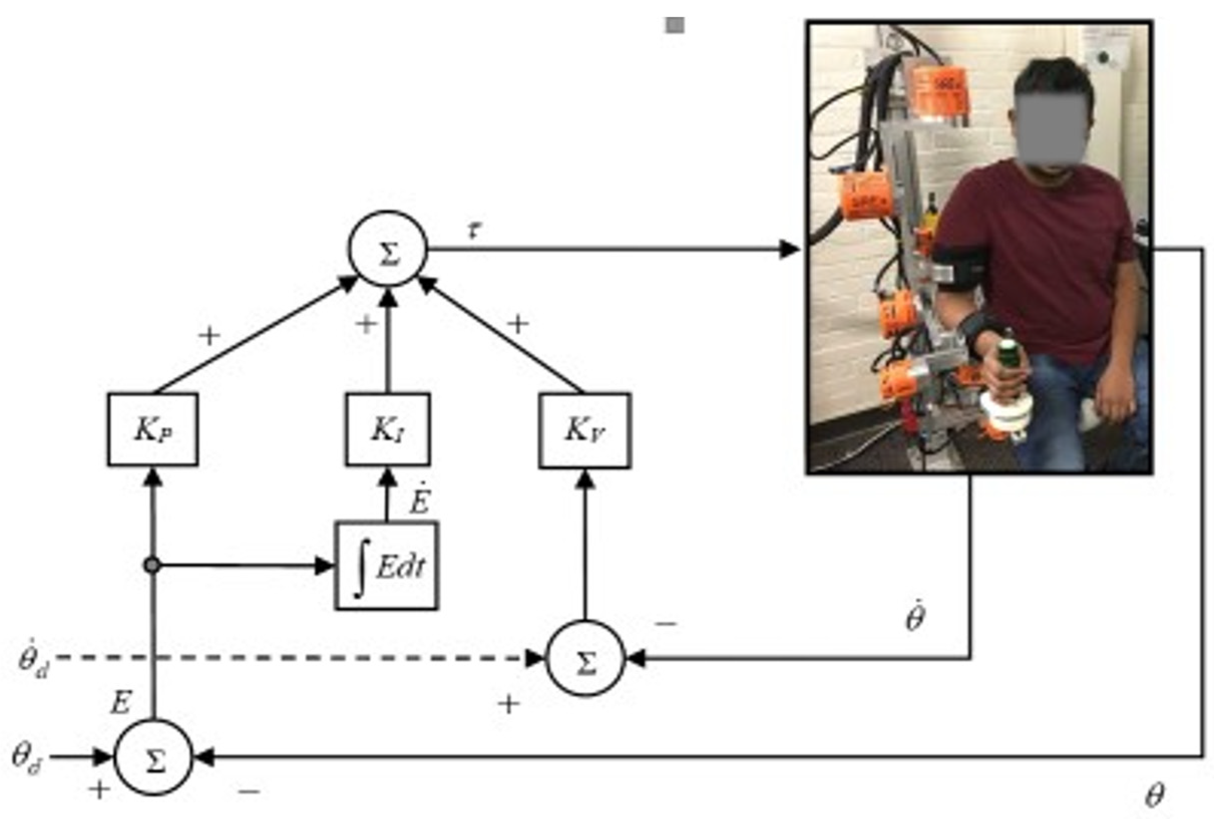
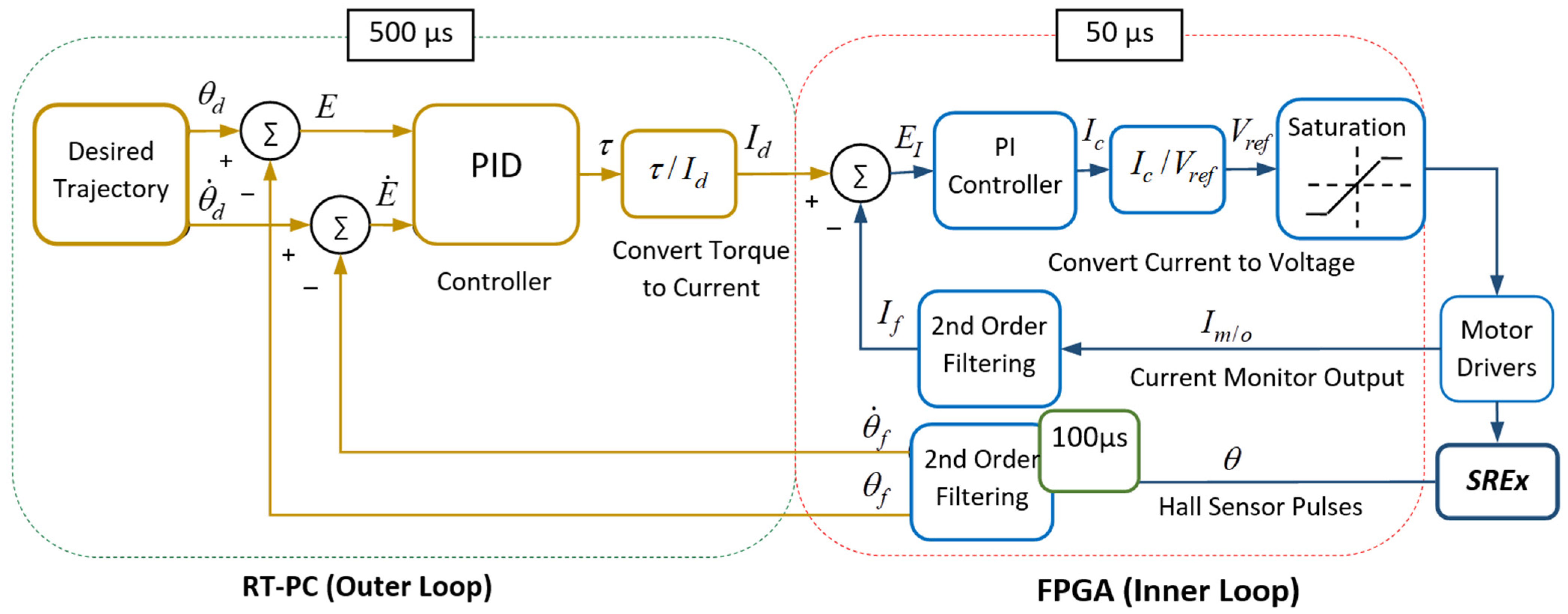
4. Control
5. Experiments and Results
5.1. Experimental Setup
5.2. Experiments and Results Analysis
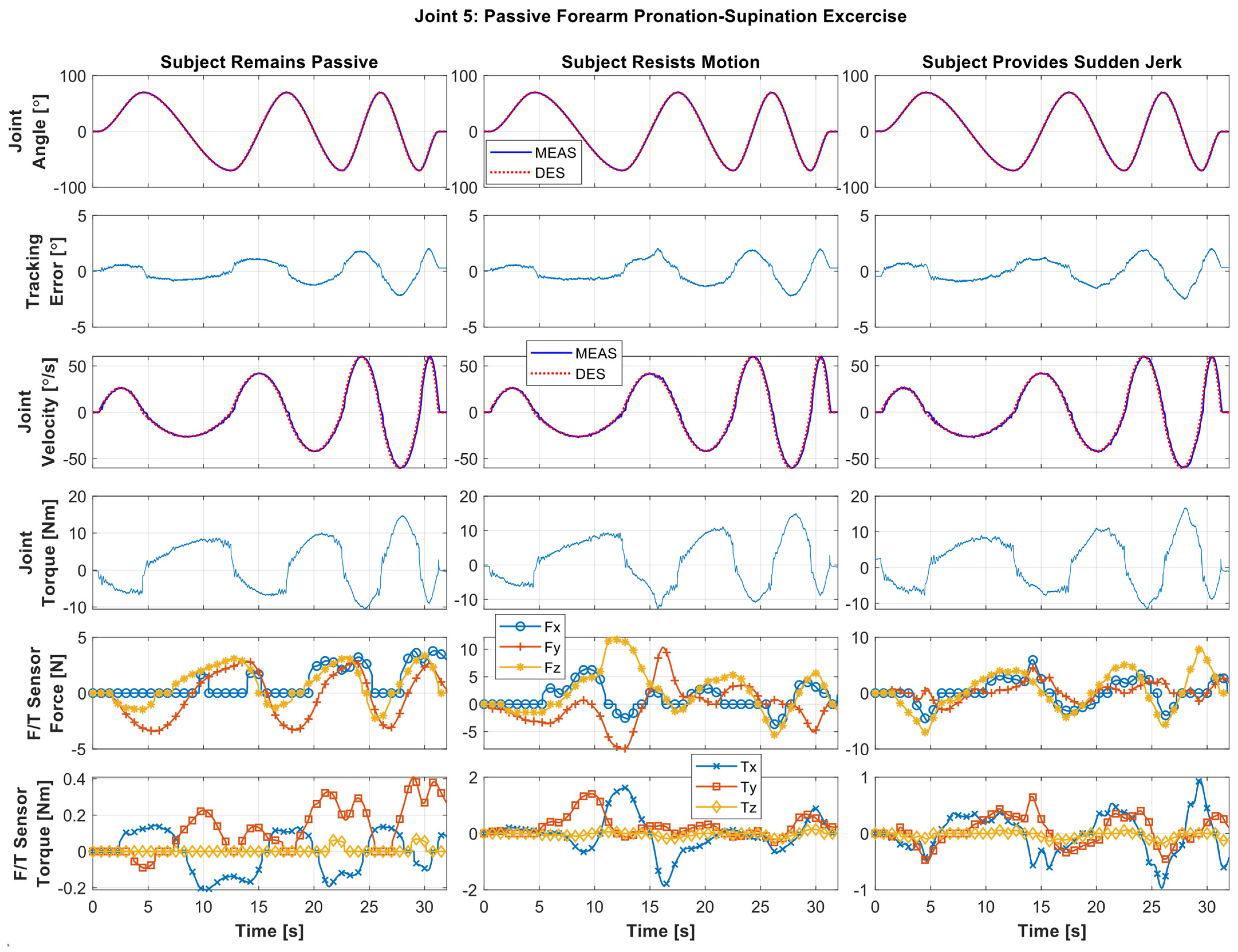
5.2.1. Individual Joint Movement Passive Exercise
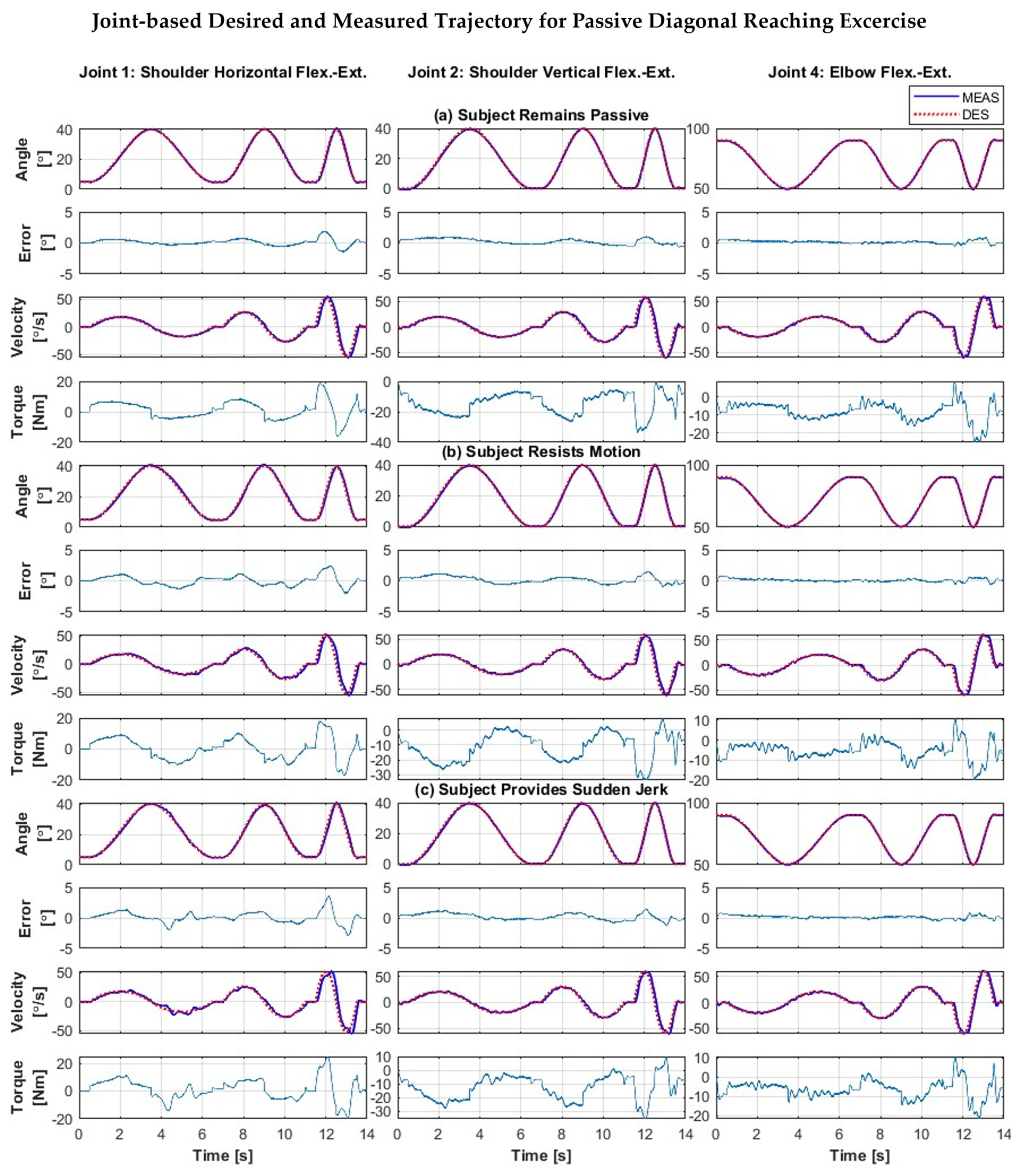
5.2.2. Composite Passive Joint Movement Exercises (Diagonal Reaching Motion)
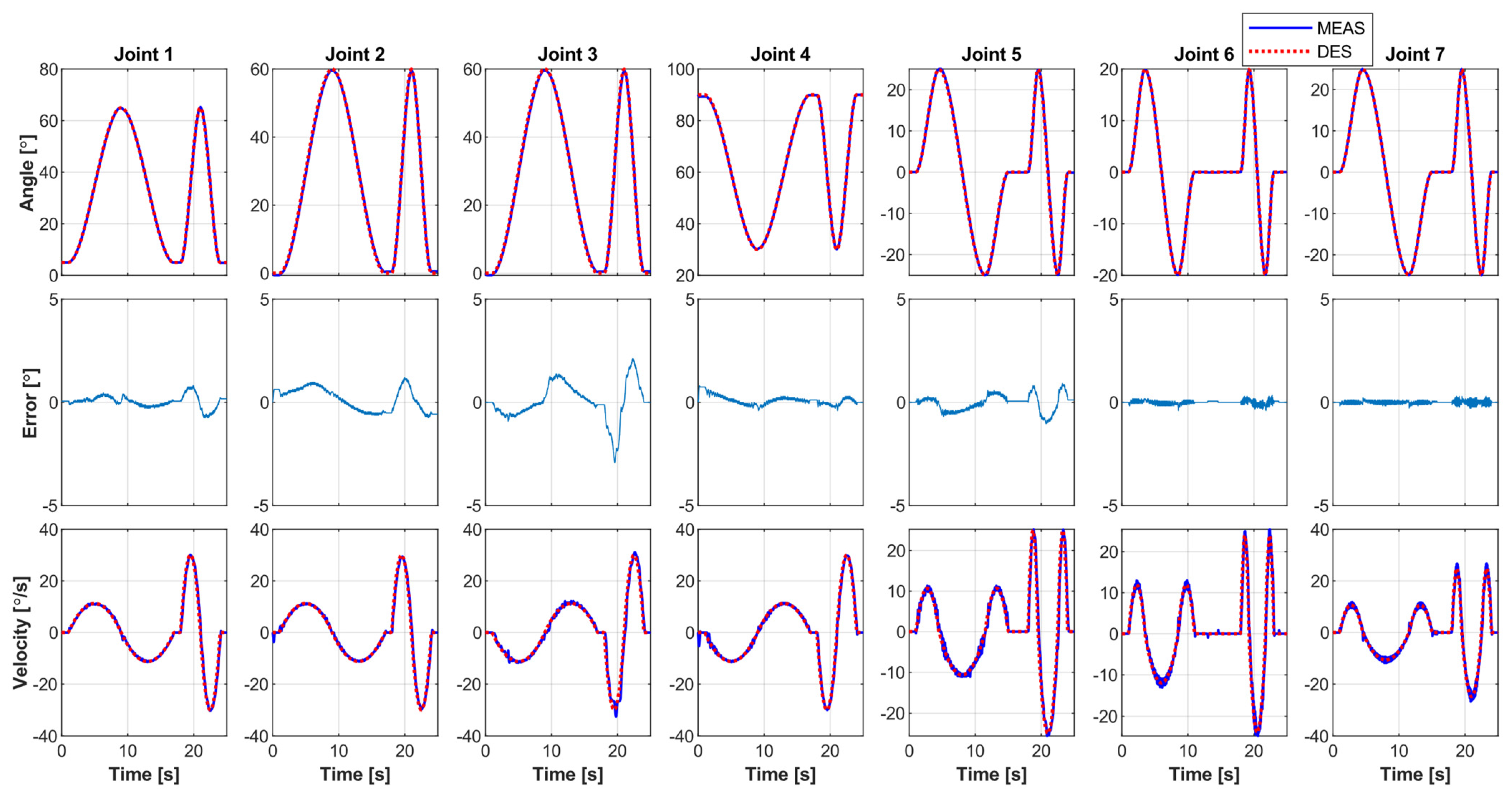
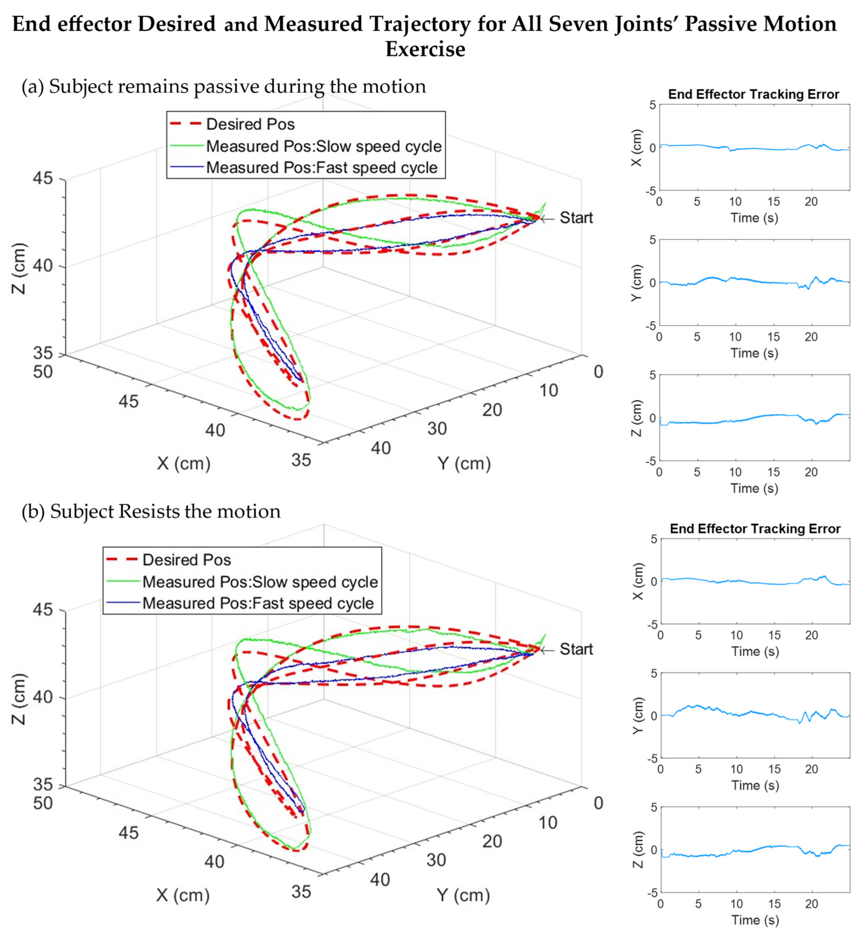
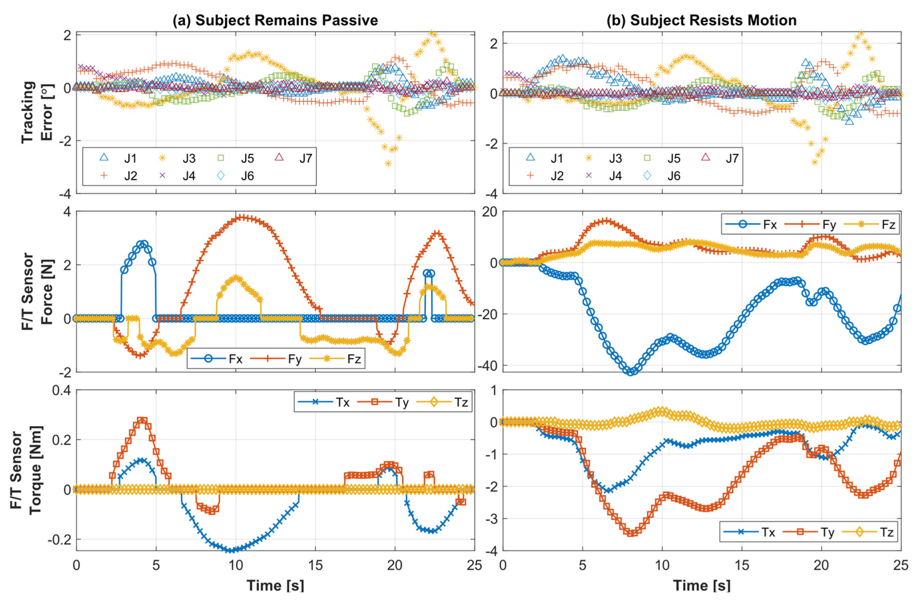
5.2.3. All Joints Simultaneous Motion (Passive)
5.2.4. Statistical Comparison
6. Conclusions
Author Contributions
Funding
Institutional Review Board Statement
Informed Consent Statement
Data Availability Statement
Conflicts of Interest
Appendix A

References
- Benjamin, E.J.; Muntner, P.; Alonso, A.; Bittencourt, M.S.; Callaway, C.W.; Carson, A.P.; Chamberlain, A.M.; Chang, A.R.; Cheng, S.; Das, S.R.; et al. Heart Disease and Stroke Statistics-2019 Update: A Report from the American Heart Association. Circulation 2019, 139, e56–e528. [Google Scholar] [CrossRef] [PubMed]
- Islam, M.R.; Spiewak, C.; Rahman, M.H.; Fareh, R. A Brief Review on Robotic Exoskeletons for Upper Extremity Rehabilitation to Find the Gap between Research Porotype and Commercial Type. Adv. Robot. Autom. 2017, 6, 3. [Google Scholar] [CrossRef]
- Louie, D.R.; Eng, J.J. Powered Robotic Exoskeletons in Post-Stroke Rehabilitation of Gait: A Scoping Review. J. Neuroeng. Rehabil. 2016, 13, 53. [Google Scholar] [CrossRef] [PubMed] [Green Version]
- Maciejasz, P.; Eschweiler, J.; Gerlach-Hahn, K.; Jansen-Troy, A.; Leonhardt, S. A Survey on Robotic Devices for Upper Limb Rehabilitation. J. Neuroeng. Rehabil. 2014, 11, 3. [Google Scholar] [CrossRef] [Green Version]
- Mozaffarian, D.; Benjamin, E.J.; Go, A.S.; Arnett, D.K.; Blaha, M.J.; Cushman, M.; de Ferranti, S.; Despres, J.P.; Fullerton, H.J.; Howard, V.J.; et al. Heart Disease and Stroke Statistics—2015 Update: A Report from the American Heart Association. Circulation 2015, 131, e29–e322. [Google Scholar] [CrossRef] [Green Version]
- Bai, S.; Christensen, S.; Islam, M.R.U. An Upper-Body Exoskeleton with a Novel Shoulder Mechanism for Assistive Applications. In Proceedings of the 2017 IEEE International Conference on Advanced Intelligent Mechatronics (AIM), Munich, Germany, 3–7 July 2017. [Google Scholar]
- Gopura, R.A.R.C.; Kiguchi, K.; Li, Y. Sueful-7: A 7dof Upper-Limb Exoskeleton Robot with Muscle-Model-Oriented Emg-Based Control. In Proceedings of the 2009 IEEE/RSJ International Conference on Intelligent Robots and Systems, St. Louis, MO, USA, 10–15 October 2009. [Google Scholar]
- Islam, M.R.; Assad-Uz-Zaman, M.; Brahmi, B.; Bouteraa, Y.; Wang, I.; Rahman, M.H. Design and Development of an Upper Limb Rehabilitative Robot with Dual Functionality. Micromachines 2021, 12, 870. [Google Scholar] [CrossRef]
- Liu, L.; Shi, Y.Y.; Xie, L. A Novel Multi-Dof Exoskeleton Robot for Upper Limb Rehabilitation. J. Mech. Med. Biol. 2016, 16, 1640023. [Google Scholar] [CrossRef] [Green Version]
- Xiao, F.Y.; Gao, Y.S.; Wang, Y.; Zhu, Y.H.; Zhao, J. Design and Evaluation of a 7-Dof Cable-Driven Upper Limb Exoskeleton. J. Mech. Sci. Technol. 2018, 32, 855–864. [Google Scholar] [CrossRef]
- Colombo, R.; Pisano, F.; Micera, S.; Mazzone, A.; Delconte, C.; Carrozza, M.C.; Dario, P.; Minuco, G. Robotic Techniques for Upper Limb Evaluation and Rehabilitation of Stroke Patients. IEEE Trans. Neural Syst. Rehabil. Eng. 2005, 13, 311–324. [Google Scholar] [CrossRef]
- Hesse, S.; Schulte-Tigges, G.; Konrad, M.; Bardeleben, A.; Werner, C. Robot-Assisted Arm Trainer for the Passive and Active Practice of Bilateral Forearm and Wrist Movements in Hemiparetic Subjects 1 1 an Organization with Which 1 or More of the Authors Is Associated Has Received or Will Receive Financial Benefits from a Commercial Party Having a Direct Financial Interest in the Results of the Research Supporting This Article. Arch. Phys. Med. Rehabil. 2003, 84, 915–920. [Google Scholar]
- Hogan, N.; Krebs, H.I.; Charnnarong, J.; Srikrishna, P.; Sharon, A. Mit-Manus: A Workstation for Manual Therapy and Training. I. In Proceedings of the IEEE International Workshop on Robot and Human Communication, Tokyo, Japan, 1–3 September 1992. [Google Scholar]
- Krebs, H.I.; Volpe, B.T.; Williams, D.; Celestino, J.; Charles, S.K.; Lynch, D.; Hogan, N. Robot-Aided Neurorehabilitation: A Robot for Wrist Rehabilitation. IEEE Trans. Neural Syst. Rehabil. Eng. 2007, 15, 327–335. [Google Scholar] [CrossRef] [PubMed] [Green Version]
- Kwakkel, G.; Kollen, B.J.; van der Grond, J.; Prevo, A.J. Probability of Regaining Dexterity in the Flaccid Upper Limb: Impact of Severity of Paresis and Time since Onset in Acute Stroke. Stroke 2003, 34, 2181–2186. [Google Scholar] [CrossRef] [PubMed] [Green Version]
- Sanchez, R.; Reinkensmeyer, D.; Shah, P.; Liu, J.; Rao, S.; Smith, R.; Cramer, S.; Rahman, T.; Bobrow, J. Monitoring Functional Arm Movement for Home-Based Therapy after Stroke. In Proceedings of the 26th Annual International Conference of the IEEE Engineering in Medicine and Biology Society, San Francisco, CA, USA, 1–5 September 2004. [Google Scholar]
- Amabile, C.; Bull, A.M.J.; Kedgley, A.E. The Centre of Rotation of the Shoulder Complex and the Effect of Normalisation. J. Biomech. 2016, 49, 1938–1943. [Google Scholar] [CrossRef] [PubMed] [Green Version]
- Balasubramanian, S.; He, J.P. Adaptive Control of a Wearable Exoskeleton for Upper-Extremity Neurorehabilitation. Appl. Bionics Biomech. 2012, 9, 99–115. [Google Scholar] [CrossRef]
- Islam, M.; Assad-Uz-Zaman, M.; Rahman, M.H. Design and Control of an Ergonomic Robotic Shoulder for Wearable Exoskeleton Robot for Rehabilitation. Int. J. Dyn. Control 2019, 8, 312–325. [Google Scholar] [CrossRef]
- Islam, M.R.; Rahmani, M.; Rahman, M.H. A Novel Exoskeleton with Fractional Sliding Mode Control for Upper Limb Rehabilitation. Robotica 2020, 38, 2099–2120. [Google Scholar] [CrossRef]
- Jarrett, C.; McDaid, A.J. Robust Control of a Cable-Driven Soft Exoskeleton Joint for Intrinsic Human-Robot Interaction. IEEE Trans. Neural Syst. Rehabil. Eng. 2017, 25, 976–986. [Google Scholar] [CrossRef]
- Kiguchi, K.; Hayashi, Y. An Emg-Based Control for an Upper-Limb Power-Assist Exoskeleton Robot. IEEE Trans. Syst. Man Cybern. Part B 2012, 42, 1064–1071. [Google Scholar] [CrossRef]
- Kim, B.; Deshpande, A.D. An Upper-Body Rehabilitation Exoskeleton Harmony with an Anatomical Shoulder Mechanism: Design, Modeling, Control, and Performance Evaluation. Int. J. Robot. Res. 2017, 36, 414–435. [Google Scholar] [CrossRef]
- Rahman, M.H.; Rahman, M.J.; Cristobal, O.L.; Saad, M.; Kenné, J.P.; Archambault, P.S. Development of a Whole Arm Wearable Robotic Exoskeleton for Rehabilitation and to Assist Upper Limb Movements. Robotica 2014, 33, 19–39. [Google Scholar] [CrossRef] [Green Version]
- Razzaghian, A.; Moghaddam, R.K. Fuzzy Sliding Mode Control of 5 Dof Upper-Limb Exoskeleton Robot. In Proceedings of the 2015 International Congress on Technology, Communication and Knowledge (ICTCK), Mashhad, Iran, 11–12 November 2015. [Google Scholar]
- Takaiwa, M.; Noritsugu, T. Wrist Rehabilitaion Equipment Using Pneumatic Parallel Manipulator. In Proceedings of the 2010 World Automation Congress, Kobe, Japan, 19–23 September 2010. [Google Scholar]
- Zhang, L.G.; Guo, S.A.; Sun, Q. Development and Assist-as-Needed Control of an End-Effector Upper Limb Rehabilitation Robot. Appl. Sci. 2020, 10, 6684. [Google Scholar] [CrossRef]
- Dalla Gasperina, S.; Roveda, L.; Pedrocchi, A.; Braghin, F.; Gandolla, M. Review on Patient-Cooperative Control Strategies for Upper-Limb Rehabilitation Exoskeletons. Front. Robot. AI 2021, 8, 745018. [Google Scholar] [CrossRef] [PubMed]
- Babaiasl, M.; Goldar, S.N.; Barhaghtalab, M.H.; Meigoli, V. Sliding Mode Control of an Exoskeleton Robot for Use in Upper-Limb Rehabilitation. In Proceedings of the 2015 3rd RSI International Conference on Robotics and Mechatronics (ICROM), Tehran, Iran, 7–9 October 2015. [Google Scholar]
- Brahmi, B.; Rahman, M.; Saad, M.; Luna, C.O.; Islam, M.R. Sliding Mode-Backstepping Control for Upper-Limb Rehabilitation with the Ets-Marse Exoskeleton Robot; RESNA: Arlington, VA, USA, 2016. [Google Scholar]
- Cui, X.; Chen, W.; Jin, X.; Agrawal, S.K. Design of a 7-Dof Cable-Driven Arm Exoskeleton (Carex-7) and a Controller for Dexterous Motion Training or Assistance. IEEE/ASME Trans. Mechatron. 2017, 22, 161–172. [Google Scholar] [CrossRef]
- Fellag, R.; Benyahia, T.; Drias, M.; Guiatni, M.; Hamerlain, M. Sliding Mode Control of a 5 Dofs Upper Limb Exoskeleton Robot. In Proceedings of the 2017 5th International Conference on Electrical Engineering—Boumerdes (ICEE-B), Boumerdes, Algeria, 29–31 October 2017. [Google Scholar]
- Mushage, B.O.; Chedjou, J.C.; Kyamakya, K. Fuzzy Neural Network and Observer-Based Fault-Tolerant Adaptive Nonlinear Control of Uncertain 5-Dof Upper-Limb Exoskeleton Robot for Passive Rehabilitation. Nonlinear Dyn. 2017, 87, 2021–2037. [Google Scholar] [CrossRef]
- Han, S.S.; Wang, H.P.; Tian, Y. Model-Free Based Adaptive Nonsingular Fast Terminal Sliding Mode Control with Time-Delay Estimation for a 12 Dof Multi-Functional Lower Limb Exoskeleton. Adv. Eng. Softw. 2018, 119, 38–47. [Google Scholar] [CrossRef]
- Wang, X.F.; Li, X.; Wang, J.H.; Fang, X.K.; Zhu, X.F. Data-Driven Model-Free Adaptive Sliding Mode Control for the Multi Degree-of-Freedom Robotic Exoskeleton. Inf. Sci. 2016, 327, 246–257. [Google Scholar] [CrossRef]
- Rahmani, M.; Rahman, M.H. An Upper-Limb Exoskeleton Robot Control Using a Novel Fast Fuzzy Sliding Mode Control. J. Intell. Fuzzy Syst. 2019, 36, 2581–2592. [Google Scholar] [CrossRef]
- Teng, L.; Bai, S. Fuzzy Sliding Mode Control of an Upper-Limb Exoskeleton Robot. In Proceedings of the 2019 IEEE International Conference on Cybernetics and Intelligent Systems (CIS) and IEEE Conference on Robotics, Automation and Mechatronics (RAM), Bangkok, Thailand, 18–20 November 2019. [Google Scholar]
- Alt Murphy, M.; Willen, C.; Sunnerhagen, K.S. Kinematic Variables Quantifying Upper-Extremity Performance after Stroke During Reaching and Drinking from a Glass. Neurorehabilit. Neural Repair 2011, 25, 71–80. [Google Scholar] [CrossRef]
- Thielman, G.T.; Dean, C.M.; Gentile, A.M. Rehabilitation of Reaching after Stroke: Task-Related Training Versus Progressive Resistive Exercise. Arch. Phys. Med. Rehabil 2004, 85, 1613–1618. [Google Scholar] [CrossRef]
- Liang, G.; Ye, W.; Xie, Q. Pid Control for the Robotic Exoskeleton Arm: Application to Rehabilitation. In Proceedings of the 31st Chinese Control Conference, Hefei, China, 25–27 July 2012. [Google Scholar]
- Wu, Q.C.; Wang, X.S.; Du, F.P.; Zhang, X.B. Design and Control of a Powered Hip Exoskeleton for Walking Assistance. Int. J. Adv. Robot. Syst. 2015, 12, 18. [Google Scholar] [CrossRef] [Green Version]
- Wu, Q.; Wang, X.; Chen, B.; Wu, H. Patient-Active Control of a Powered Exoskeleton Targeting Upper Limb Rehabilitation Training. Front. Neurol. 2018, 9, 817. [Google Scholar] [CrossRef] [PubMed]
- Hasan, S.K.; Dhingra, A.K. Performance Verification of Different Control Schemes in Human Lower Extremity Rehabilitation Robot. Results Control Optim. 2021, 4, 100028. [Google Scholar] [CrossRef]
- Lenarčič, J.; Klopčar, N. Positional Kinematics of Humanoid Arms. Robotica 2005, 24, 105–112. [Google Scholar] [CrossRef]
- Craig, J.J. Introduction to Robotics: Mechanics and Control; Pearson Educacion: London, UK, 2005. [Google Scholar]
- Kelly, R.; Davila, V.S.; Perez, J.A.L. Control of Robot Manipulators in Joint Space; Springer Science & Business Media: Berlin, Germany, 2005. [Google Scholar]
- Wu, Q.; Wu, H. Development, Dynamic Modeling, and Multi-Modal Control of a Therapeutic Exoskeleton for Upper Limb Rehabilitation Training. Sensors 2018, 18, 3611. [Google Scholar] [CrossRef] [PubMed] [Green Version]


| Actuators (Brushless), maxon precision motors, Inc., Taunton, USA | ||||
| Specification | EC 90 Flat 160 W (Joints 1 and 2) | EC 45 Flat 70 W (Joint 3) | EC 90, Flat 90 W (Joint 4) | EC 45, Flat 30 W (Joints 5, 6, and 7) |
| Nominal Voltage (V) | 24 | 24 | 24 | 24 |
| Nominal Speed (rpm) | 2720 | 4860 | 2590 | 2940 |
| Torque Constant (mNm/A) | 71.2 | 36.9 | 70.5 | 51 |
| Weight (g) | 630 | 141 | 600 | 75 |
| Strain wave Gear, Harmonic Drive LLC, Beverly, USA | ||||
| Specification: CSF | 17-100-2UH-LW (Joints 1 and 2) | 14-100-2XH-F (Joint 4) | 11-100-2XH-F (Joints 3 and 5–7) | |
| Torque at 2000 rpm (Nm) | 24 | 7.8 | 5 | |
| Momentary Peak Torque (Nm) | 108 | 54 | 25 | |
| Repeated Peak Torque (Nm) | 54 | 28 | 11 | |
| Gear Ratio | 100 | 100 | 100 | |
| Anti-Backlash Gear and Ring Gear (Pressure angle: 20°, Pitch: 32), Sterling Instrument, Hicksville, USA | ||||
| Specification | Anti-Backlash Spur Gear, S1A86A-C032A062 (Joints 3 and 5) | Ring Spur Gear (custom) | ||
| Joint 3 | Joint 5 | |||
| Number of teeth | 62 | 186 | 143 | |
| Bore Diameter (mm) | 6.35 | 120 | 85 | |
| F/T Sensor: RFT60-HA01 with EtherCAT Adapter: RFTEC-02, Robotus, Seongnam-si, South Korea | ||||
| Parameters | Fx, Fy | Fz | Tx, Ty, Tz | |
| Load Capacity | 150 N | 200 N | 4 Nm | |
| Resolution | 100 mN | 150 mN | 5 mNm | |
| Link | Joints | Link Mass (kg) | Center of Gravity, CG (m) | Moment of Inertia, I (kg·m2) | Segment Length (m) | |||||
|---|---|---|---|---|---|---|---|---|---|---|
| CGx | CGy | CGz | Ixx | Iyy | Izz | |||||
| 1 | 1–2 | 2.9 | 0.0003 | 0.1290 | −0.0428 | 0.0208 | 0.0136 | 0.0111 | Base frame to Shoulder joint | 0.146 |
| 2 | 2–3 | 1.2 | −0.0356 | −0.1419 | 0.0772 | 0.0056 | 0.0033 | 0.0065 | ||
| 3 | 3–4 | 1.9 | −0.0040 | 0.1111 | −0.0213 | 0.0091 | 0.0060 | 0.0071 | Shoulder joint to Elbow joint | 0.281 ± 0.033 |
| 4 | 4–5 | 0.9 | −0.0443 | −0.1319 | 0.0417 | 0.0037 | 0.0029 | 0.0039 | ||
| 5 | 5–6 | 0.8 | −0.0074 | 0.0942 | −0.0362 | 0.0057 | 0.0018 | 0.0046 | Elbow joint to Wrist Joint | 0.281 ± 0.035 |
| 6 | 6–7 | 0.6 | 0.0003 | −0.1060 | 0.0469 | 0.0036 | 0.0024 | 0.0014 | ||
| 7 | 7-Tip | 0.4 | 0.0777 | −0.0001 | −0.0658 | 0.0007 | 0.0011 | 0.0006 | Wrist joint to the tip | 0.083 ± 0.041 |
| Joint Motion and Workspace | DH Parameters | |||||
|---|---|---|---|---|---|---|
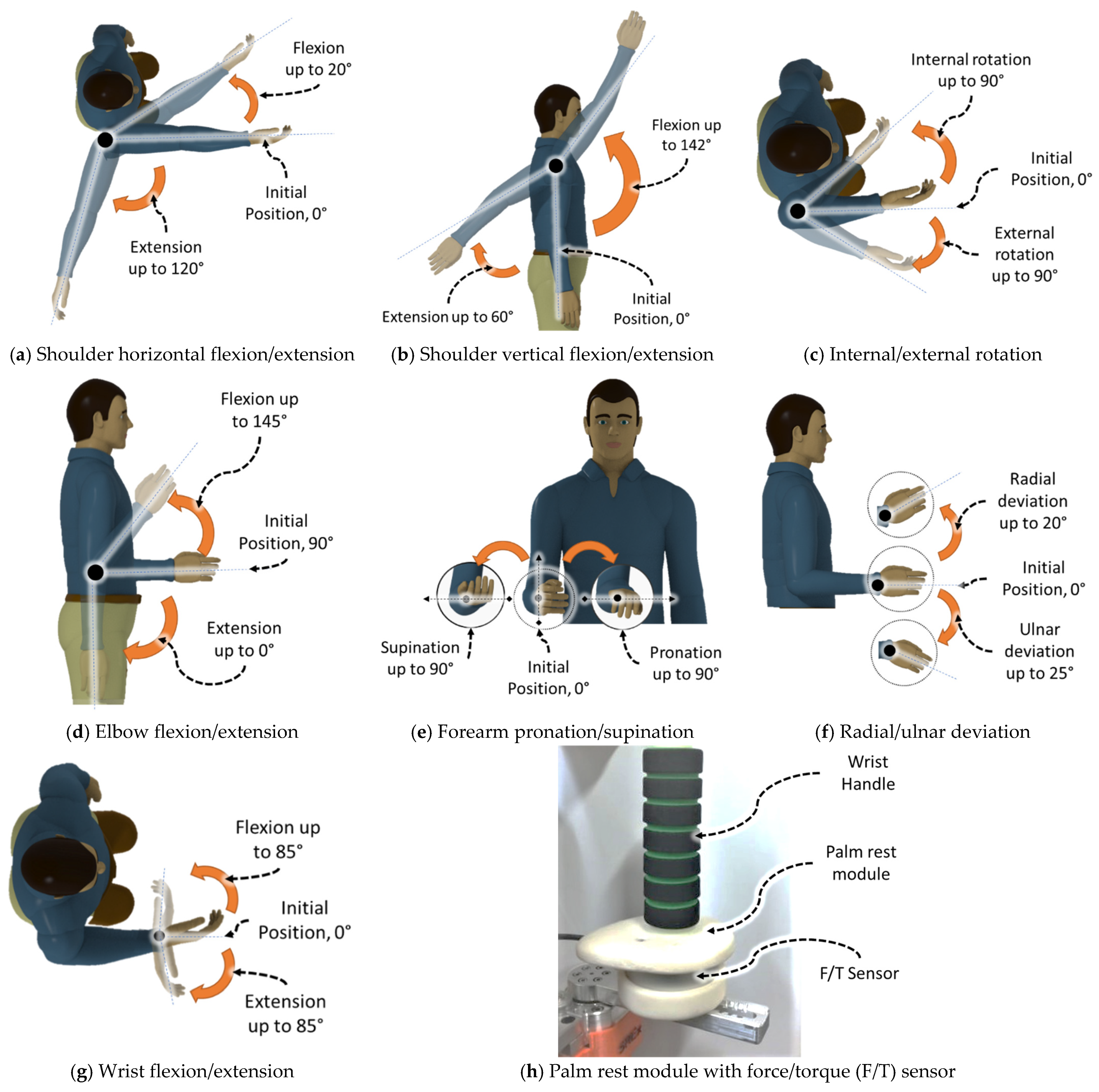
| Joints | Motion | Joint Angles | αi−1 | di | ai−1 | θi |
| 1 | Shoulder joint horizontal flexion/extension | 20/120° | 0 | ds | 0 | θ1 |
| 2 | Shoulder joint vertical flexion/extension | 142/60° | −π/2 | 0 | 0 | θ2 |
| 3 | Shoulder joint internal/external rotation | 90/90° | π/2 | de | 0 | θ3 |
| 4 | Elbow joint flexion/extension | 145/0° | −π/2 | 0 | 0 | θ4 |
| 5 | Forearm joint pronation/supination | 90/90° | π/2 | dw | 0 | θ5 |
| 6 | Wrist joint radial/ulnar deviation | 20/25° | −π/2 | 0 | 0 | θ6 − π/2 |
| 7 | Wrist joint flexion/extension | 85/85° | −π/2 | 0 | 0 | θ7 |
| Tip | Wrist handle with Force/Torque Sensor | N/A | 0 | 0 | atip | N/A |
| Age (years) | Height (cm) | Weight (kg) | |
|---|---|---|---|
| Subject A | 25 | 172.7 | 80 |
| Subject B | 28 | 177.8 | 82 |
| Subject C | 26 | 175.2 | 78 |
| Subject D | 44 | 161.5 | 63 |
| Subject E | 30 | 162.5 | 68 |
| Mode of Exercise | Subject A * | Subject B | Subject C | ||||||||||
|---|---|---|---|---|---|---|---|---|---|---|---|---|---|
| Sensor: Force/Torque, F/T (N/Nm) | RMS F/T | Peak F/T | RMS Error e4 (°) | Peak Error e4 (°) | RMS F/T | Peak F/T | RMS Error e4 (°) | Peak Error e4 (°) | RMS F/T | Peak F/T | RMS Error e4 (°) | Peak Error e4 (°) | |
| Passive | Fx | 2.08 | 3.76 | 0.42 | 1.49 | 2.86 | 6.75 | 0.38 | 1.49 | 3.16 | 7.67 | 0.43 | 1.60 |
| Fy | 0.46 | 1.01 | 0.49 | 1.23 | 0.98 | 2.01 | |||||||
| Fz | 1.83 | 3.95 | 1.58 | 3.16 | 1.19 | 3.78 | |||||||
| Tx | 0.02 | 0.06 | 0.07 | 0.18 | 0.08 | 0.16 | |||||||
| Ty | 0.11 | 0.24 | 0.20 | 0.52 | 0.28 | 0.75 | |||||||
| Tz | 0 | 0 | 0 | 0 | 0.01 | 0.06 | |||||||
| Resistance | Fx | 4.21 | 10.16 | 0.64 | 1.95 | 6.97 | 20.41 | 0.51 | 2.06 | 4.09 | 11.86 | 0.50 | 1.72 |
| Fy | 1.34 | 3.91 | 3.40 | 10.37 | 1.70 | 5.53 | |||||||
| Fz | 9.94 | 21.03 | 8.63 | 24.38 | 3.85 | 10.75 | |||||||
| Tx | 0.12 | 0.36 | 0.32 | 1.17 | 0.14 | 0.54 | |||||||
| Ty | 0.42 | 1.19 | 0.60 | 2.47 | 0.37 | 1.24 | |||||||
| Tz | 0.01 | 0.05 | 0.05 | 0.18 | 0.02 | 0.07 | |||||||
| Sudden Jerk | Fx | 2.77 | 6.01 | 0.55 | 2.06 | 5.15 | 16.72 | 0.41 | 1.60 | 3.47 | 9.38 | 0.47 | 1.78 |
| Fy | 1.05 | 2.09 | 2.77 | 9.74 | 1.09 | 2.01 | |||||||
| Fz | 5.96 | 12.27 | 4.94 | 14.80 | 2.62 | 9.41 | |||||||
| Tx | 0.08 | 0.16 | 0.28 | 1.16 | 0.08 | 0.22 | |||||||
| Ty | 0.28 | 0.66 | 0.36 | 0.85 | 0.32 | 0.97 | |||||||
| Tz | 0.02 | 0.11 | 0.03 | 0.12 | 0.02 | 0.07 | |||||||
| Mode of Exercise | Subject A | Subject B | Subject C * | ||||||||||
|---|---|---|---|---|---|---|---|---|---|---|---|---|---|
| Sensor: Force/Torque, F/T (N/Nm) | RMS F/T | Peak F/T | RMS Error e5 (°) | Peak Error e5 (°) | RMS F/T | Peak F/T | RMS Error e5 (°) | Peak Error e5 (°) | RMS F/T | Peak F/T | RMS Error e5 (°) | Peak Error e5 (°) | |
| Passive | Fx | 0.25 | 1.77 | 0.87 | 2.06 | 0.38 | 1.98 | 0.83 | 2.06 | 1.67 | 3.8 | 0.94 | 2.18 |
| Fy | 1.55 | 2.77 | 1.46 | 2.77 | 2.12 | 3.42 | |||||||
| Fz | 1.17 | 2.39 | 1.10 | 2.28 | 1.8 | 3.37 | |||||||
| Tx | 0.09 | 0.15 | 0.12 | 0.29 | 0.11 | 0.21 | |||||||
| Ty | 0.05 | 0.13 | 0.09 | 0.25 | 0.18 | 0.41 | |||||||
| Tz | 0 | 0 | 0 | 0 | 0.02 | 0.07 | |||||||
| Resistance | Fx | 7.79 | 17.13 | 1.05 | 2.35 | 9.46 | 19.55 | 1.07 | 2.69 | 2.40 | 6.46 | 1.01 | 2.23 |
| Fy | 5.15 | 13.39 | 5.39 | 15.03 | 3.48 | 10.37 | |||||||
| Fz | 3.22 | 7.02 | 6.74 | 16.77 | 4.63 | 12.19 | |||||||
| Tx | 1 | 2.44 | 1.24 | 3.77 | 0.65 | 1.85 | |||||||
| Ty | 0.56 | 1.24 | 0.65 | 1.45 | 0.45 | 1.41 | |||||||
| Tz | 0.14 | 0.37 | 0.13 | 0.36 | 0.08 | 0.2 | |||||||
| Sudden Jerk | Fx | 3.2 | 14.68 | 0.94 | 2.58 | 3.93 | 12.06 | 0.95 | 2.64 | 2.21 | 5.99 | 1.00 | 2.52 |
| Fy | 2.84 | 13.90 | 2.96 | 8.44 | 1.5 | 4.51 | |||||||
| Fz | 2.39 | 6.19 | 4.38 | 14.11 | 3.43 | 8.13 | |||||||
| Tx | 0.48 | 1.78 | 0.82 | 2.41 | 0.37 | 0.97 | |||||||
| Ty | 0.23 | 0.86 | 0.30 | 0.94 | 0.26 | 0.66 | |||||||
| Tz | 0.04 | 0.15 | 0.05 | 0.21 | 0.06 | 0.19 | |||||||
| Mode of Exercise | Subject A | Subject B * | Subject C | ||||||||||
|---|---|---|---|---|---|---|---|---|---|---|---|---|---|
| Sensor: Force/Torque, F/T (N/Nm) | RMS F/T | Peak F/T | Mean RMS Error e124 (°) | Mean Peak Error e124 (°) | RMS F/T | Mean Peak F/T | RMS Error e124 (°) | Mean Peak Error e124 (°) | RMS F/T | Peak F/T | Mean RMS Error e124(°) | Mean Peak Error e124 (°) | |
| Passive | Fx | 1.52 | 3.42 | 0.47 | 1.30 | 1.20 | 3.04 | 0.44 | 1.26 | 1.48 | 3.30 | 0.52 | 1.38 |
| Fy | 0.89 | 1.36 | 1.16 | 2.77 | 0.95 | 1.75 | |||||||
| Fz | 0.88 | 1.63 | 1.64 | 2.94 | 1.34 | 2.39 | |||||||
| Tx | 0.09 | 0.14 | 0.07 | 0.21 | 0.06 | 0.11 | |||||||
| Ty | 0.14 | 0.31 | 0.08 | 0.20 | 0.15 | 0.28 | |||||||
| Tz | 0 | 0 | 0 | 0 | 0 | 0 | |||||||
| Resistance | Fx | 5.03 | 10.78 | 0.63 | 1.49 | 8.49 | 18.45 | 0.55 | 1.53 | 2.37 | 6.15 | 0.61 | 1.45 |
| Fy | 3.14 | 5.62 | 4.11 | 8.34 | 1.99 | 4.56 | |||||||
| Fz | 1.03 | 1.87 | 5.52 | 10.86 | 2.11 | 5.18 | |||||||
| Tx | 0.31 | 0.55 | 0.36 | 0.75 | 0.22 | 0.52 | |||||||
| Ty | 0.50 | 1.13 | 0.61 | 1.29 | 0.19 | 0.49 | |||||||
| Tz | 0 | 0 | 0.05 | 0.16 | 0 | 0 | |||||||
| Sudden Jerk | Fx | 5.95 | 11.60 | 0.65 | 1.62 | 4.19 | 12.18 | 0.59 | 1.91 | 4.19 | 10.98 | 0.60 | 1.57 |
| Fy | 3.04 | 6.45 | 3.83 | 7.93 | 1.69 | 4.44 | |||||||
| Fz | 1.05 | 2.37 | 3.65 | 10.10 | 2.02 | 6.10 | |||||||
| Tx | 0.30 | 0.59 | 0.39 | 0.81 | 0.20 | 0.55 | |||||||
| Ty | 0.61 | 1.30 | 0.30 | 0.83 | 0.42 | 1.08 | |||||||
| Tz | 0 | 0 | 0.02 | 0.07 | 0 | 0 | |||||||
| Joints | Slow Cycle (~1 to ~17 s) | Fast Cycle (~18 to ~24 s) | ||||||
|---|---|---|---|---|---|---|---|---|
| Subject D * | Subject E | Subject D * | Subject E | |||||
| RMS Error ei (°) | Peak Velocity (°/s) | RMS Error ei (°) | Peak Velocity (°/s) | RMS Error ei (°) | Peak Velocity (°/s) | RMS Error ei (°) | Peak Velocity (°/s) | |
| 1 | 0.1660 | 11.4 | 0.2323 | 11.4 | 0.4776 | 30.3 | 0.5244 | 30.3 |
| 2 | 0.5538 | 11.3 | 0.5484 | 11.3 | 0.6143 | 29.4 | 0.6031 | 29.6 |
| 3 | 0.5957 | 12.1 | 0.5201 | 11.9 | 1.4149 | 32.5 | 1.4130 | 31.9 |
| 4 | 0.2710 | 11.5 | 0.2545 | 11.5 | 0.1365 | 30.0 | 0.1572 | 29.9 |
| 5 | 0.2908 | 11.2 | 0.2772 | 11.6 | 0.5898 | 25.6 | 0.5465 | 25.6 |
| 6 | 0.0616 | 13.1 | 0.0616 | 12.9 | 0.1107 | 25.4 | 0.1180 | 25.4 |
| 7 | 0.0521 | 11.8 | 0.0541 | 11.9 | 0.0947 | 26.7 | 0.1035 | 27.3 |
| Joints | Slow Cycle (~1 to ~17 s) | Fast Cycle (~18 to ~24 s) | ||||||
|---|---|---|---|---|---|---|---|---|
| Subject D * | Subject E | Subject D * | Subject E | |||||
| RMS Error ei (°) | Peak Velocity (°/s) | RMS Error ei (°) | Peak Velocity (°/s) | RMS Error ei (°) | Peak Velocity (°/s) | RMS Error ei (°) | Peak Velocity (°/s) | |
| 1 | 0.5647 | 11.8 | 0.2346 | 11.5 | 0.6027 | 31.2 | 0.3703 | 30.5 |
| 2 | 0.7123 | 11.4 | 0.5742 | 11.4 | 0.7475 | 29.7 | 0.7053 | 29.5 |
| 3 | 0.5995 | 11.7 | 0.5823 | 12.4 | 1.4478 | 31.9 | 1.5938 | 30.2 |
| 4 | 0.2583 | 11.6 | 0.2772 | 11.6 | 0.1598 | 29.9 | 0.2278 | 29.8 |
| 5 | 0.3195 | 11.6 | 0.3393 | 11.5 | 0.5807 | 25.5 | 0.7222 | 25.6 |
| 6 | 0.0679 | 12.9 | 0.0786 | 13.0 | 0.1044 | 25.4 | 0.1819 | 25.4 |
| 7 | 0.0487 | 11.7 | 0.0782 | 12.0 | 0.0986 | 27.1 | 0.1659 | 27.6 |
Publisher’s Note: MDPI stays neutral with regard to jurisdictional claims in published maps and institutional affiliations. |
© 2022 by the authors. Licensee MDPI, Basel, Switzerland. This article is an open access article distributed under the terms and conditions of the Creative Commons Attribution (CC BY) license (https://creativecommons.org/licenses/by/4.0/).
Share and Cite
Ahmed, T.; Islam, M.R.; Brahmi, B.; Rahman, M.H. Robustness and Tracking Performance Evaluation of PID Motion Control of 7 DoF Anthropomorphic Exoskeleton Robot Assisted Upper Limb Rehabilitation. Sensors 2022, 22, 3747. https://doi.org/10.3390/s22103747
Ahmed T, Islam MR, Brahmi B, Rahman MH. Robustness and Tracking Performance Evaluation of PID Motion Control of 7 DoF Anthropomorphic Exoskeleton Robot Assisted Upper Limb Rehabilitation. Sensors. 2022; 22(10):3747. https://doi.org/10.3390/s22103747
Chicago/Turabian StyleAhmed, Tanvir, Md Rasedul Islam, Brahim Brahmi, and Mohammad Habibur Rahman. 2022. "Robustness and Tracking Performance Evaluation of PID Motion Control of 7 DoF Anthropomorphic Exoskeleton Robot Assisted Upper Limb Rehabilitation" Sensors 22, no. 10: 3747. https://doi.org/10.3390/s22103747
APA StyleAhmed, T., Islam, M. R., Brahmi, B., & Rahman, M. H. (2022). Robustness and Tracking Performance Evaluation of PID Motion Control of 7 DoF Anthropomorphic Exoskeleton Robot Assisted Upper Limb Rehabilitation. Sensors, 22(10), 3747. https://doi.org/10.3390/s22103747