
Validation of an RF Image System for Real-Time Tracking Neurosurgical Tools

 , ,
, ,  ,
,  , ,
, ,  and
and 
Abstract
:1. Introduction
2. Materials and Methods
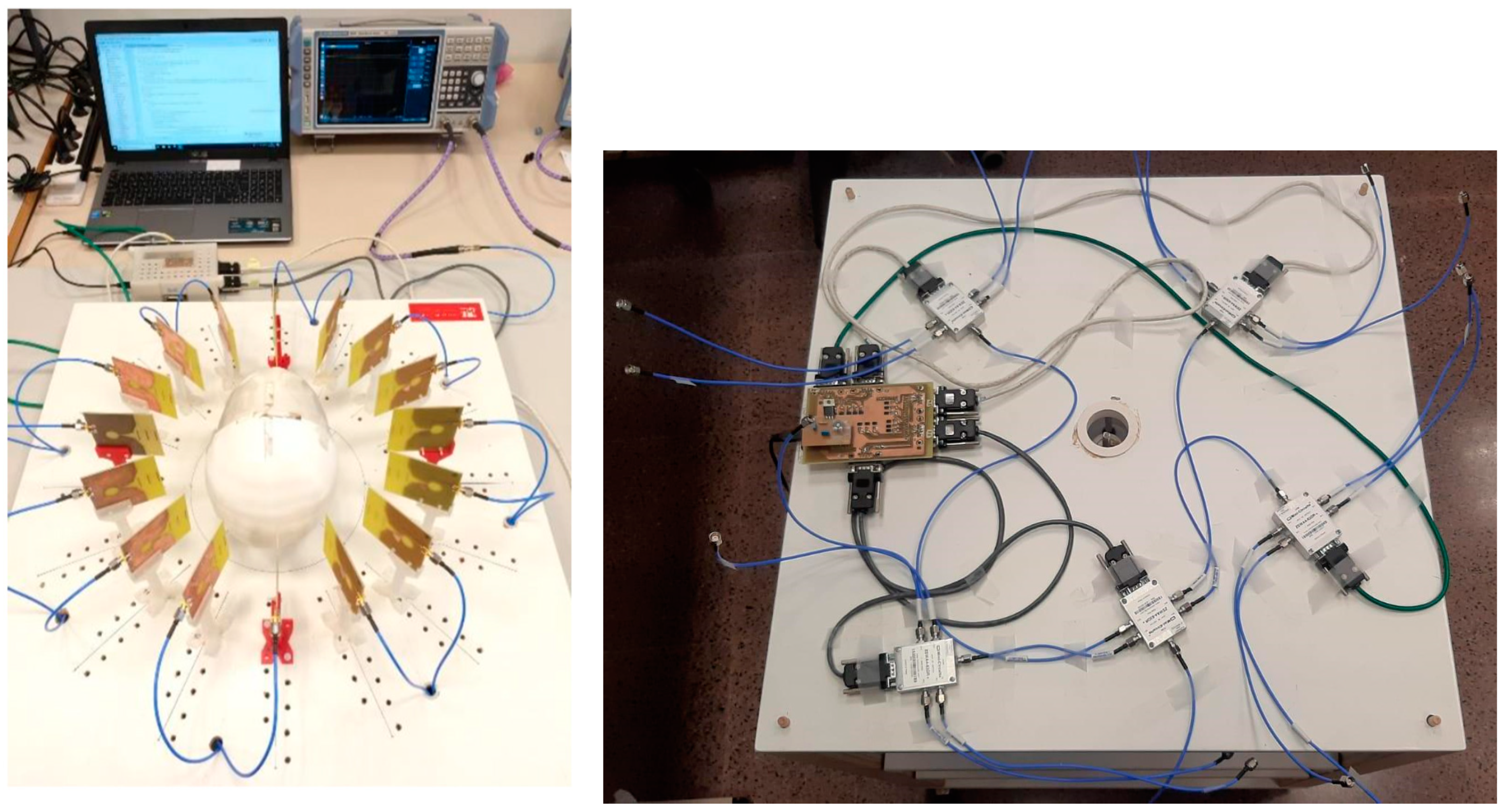
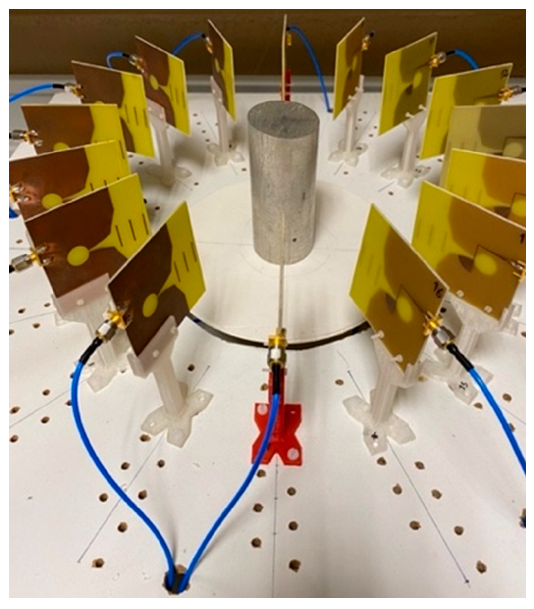
2.1. System Hardware
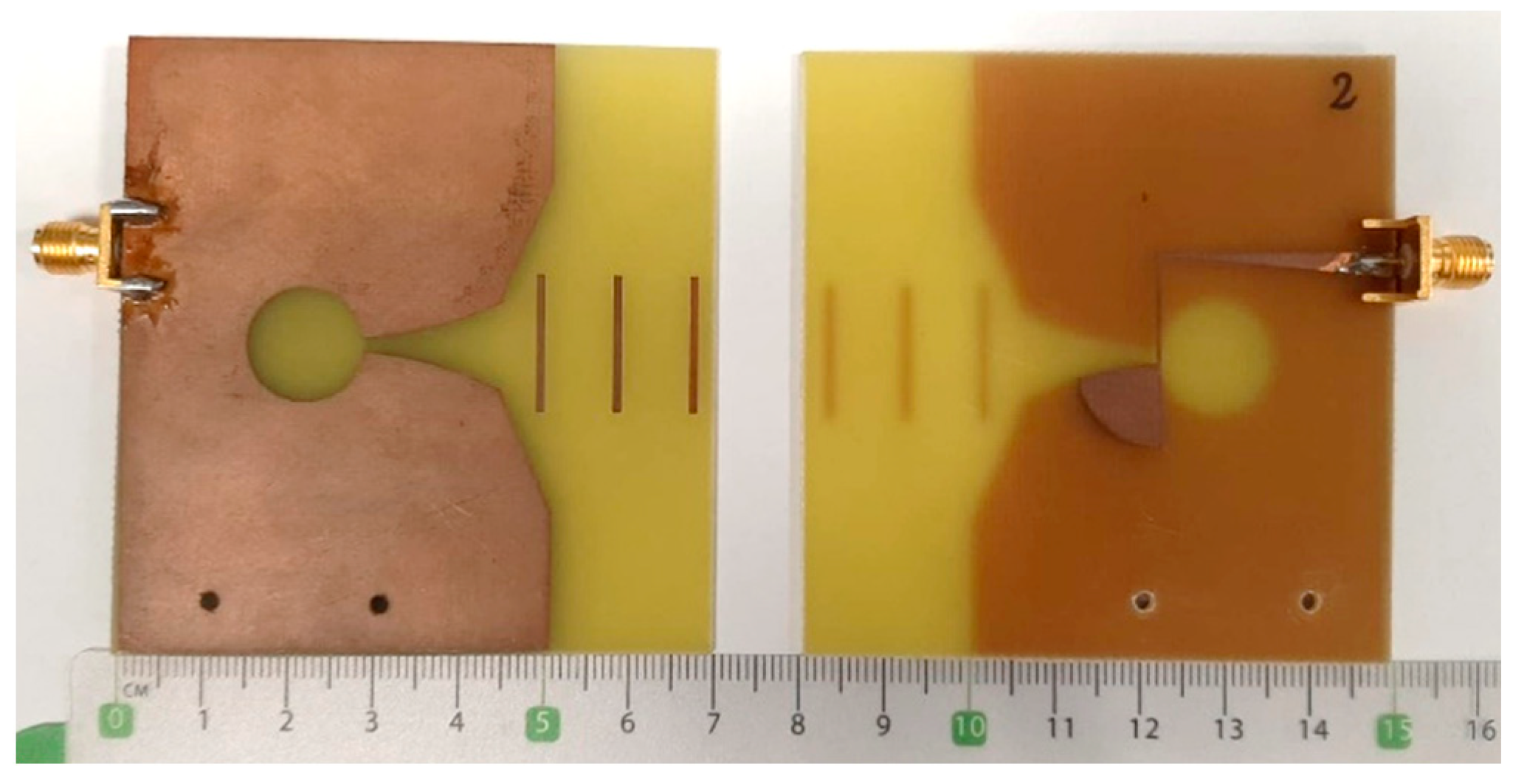
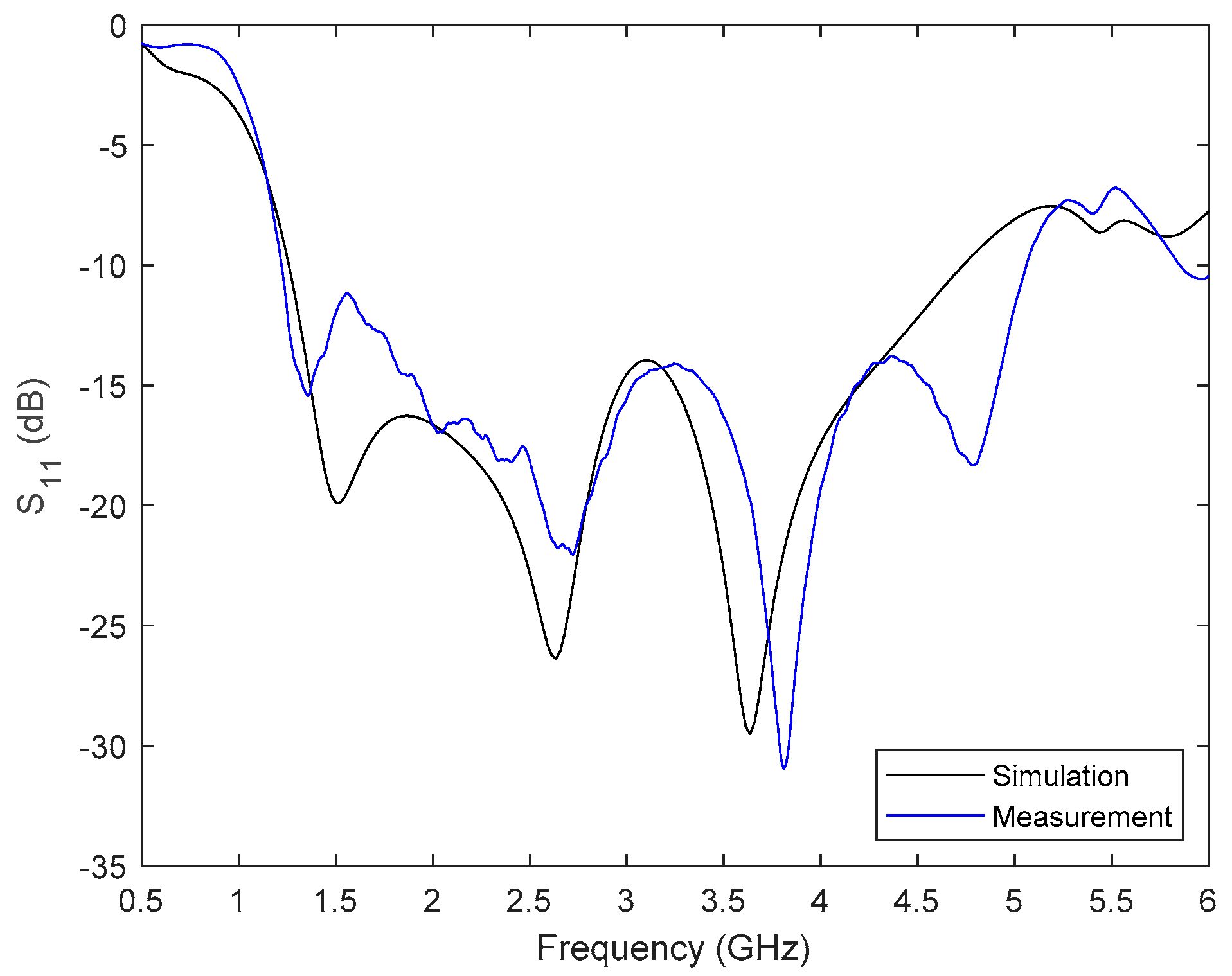
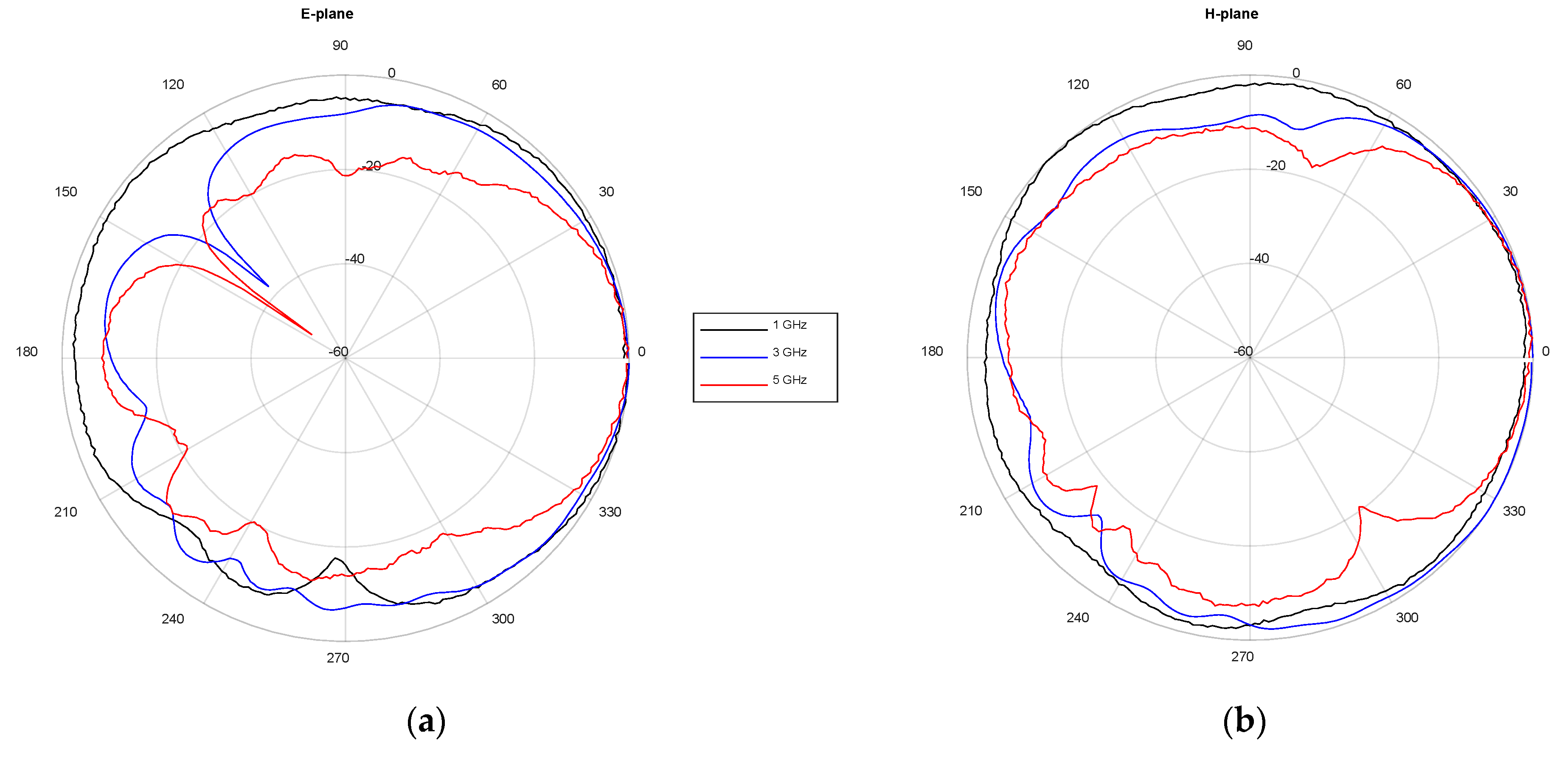
2.1.1. Antenna Design and Standard Characterization in the Frequency Domain
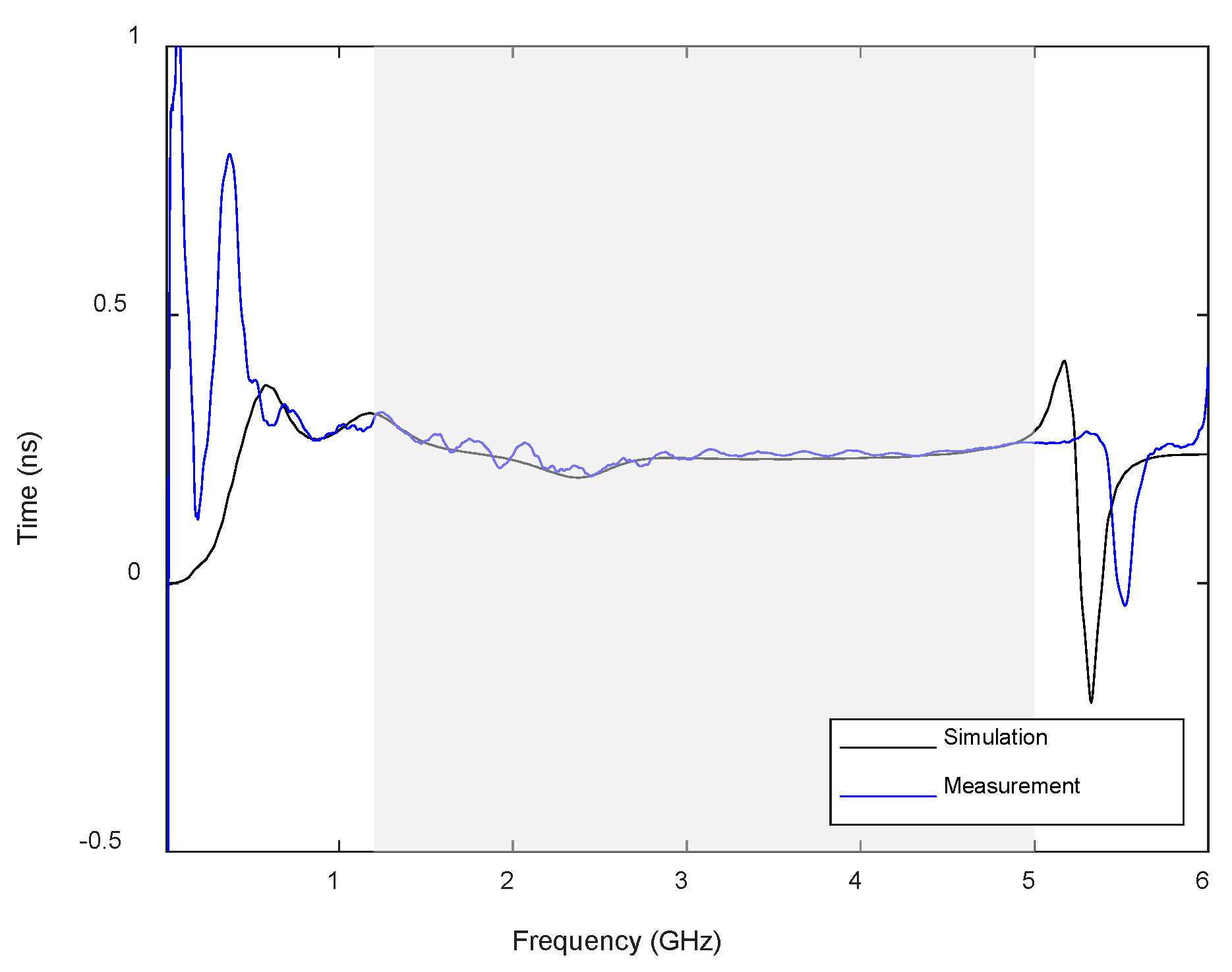
2.1.2. Antenna Time Domain Analysis
2.2. Signal Processing for Imaging
2.2.1. Delay and Sum
2.2.2. Delay Multiply and Sum
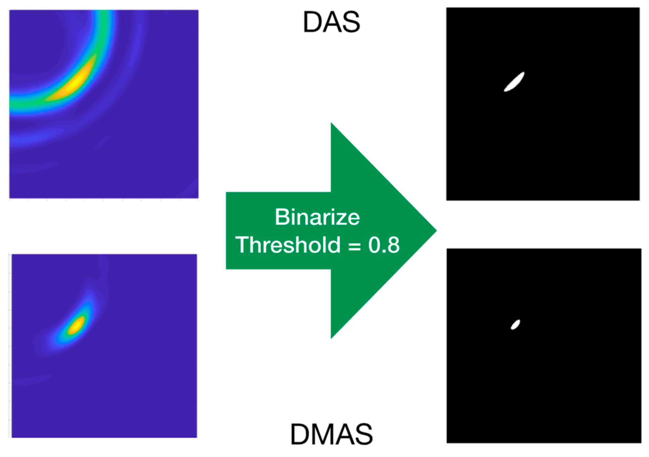
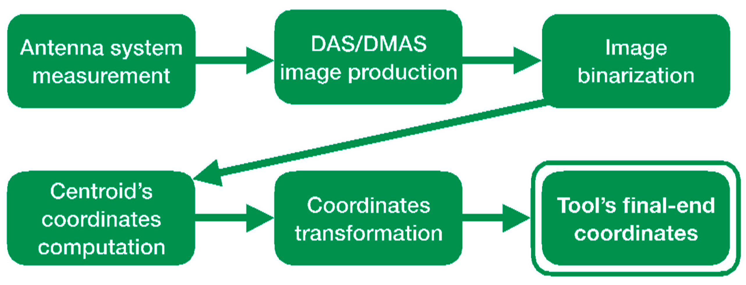
2.3. Calibration of the Imaging System
3. Experimental Validation and Results
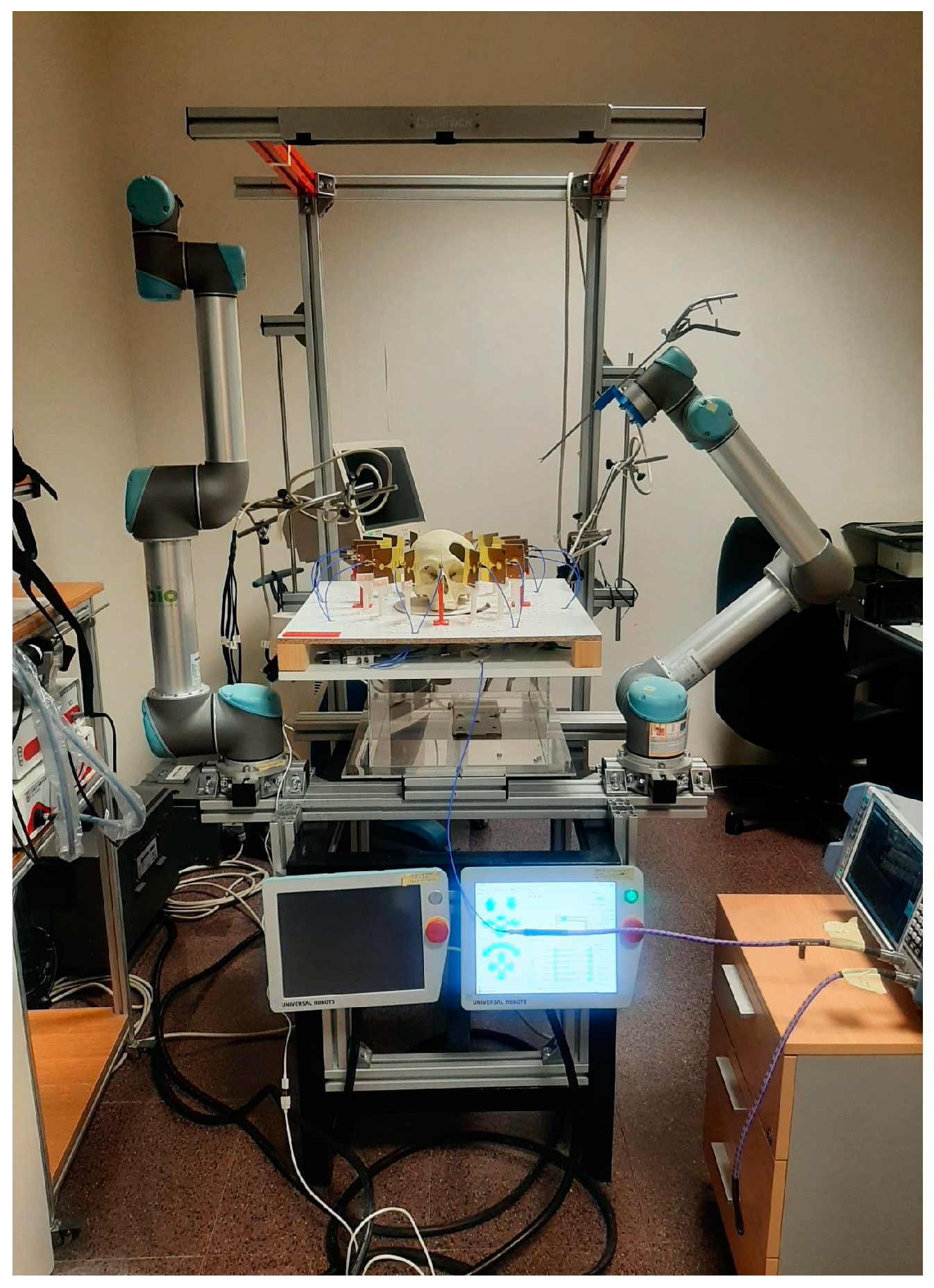
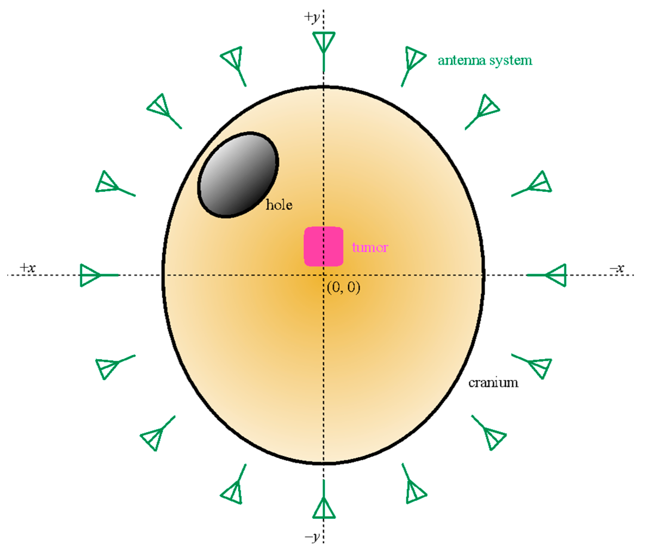
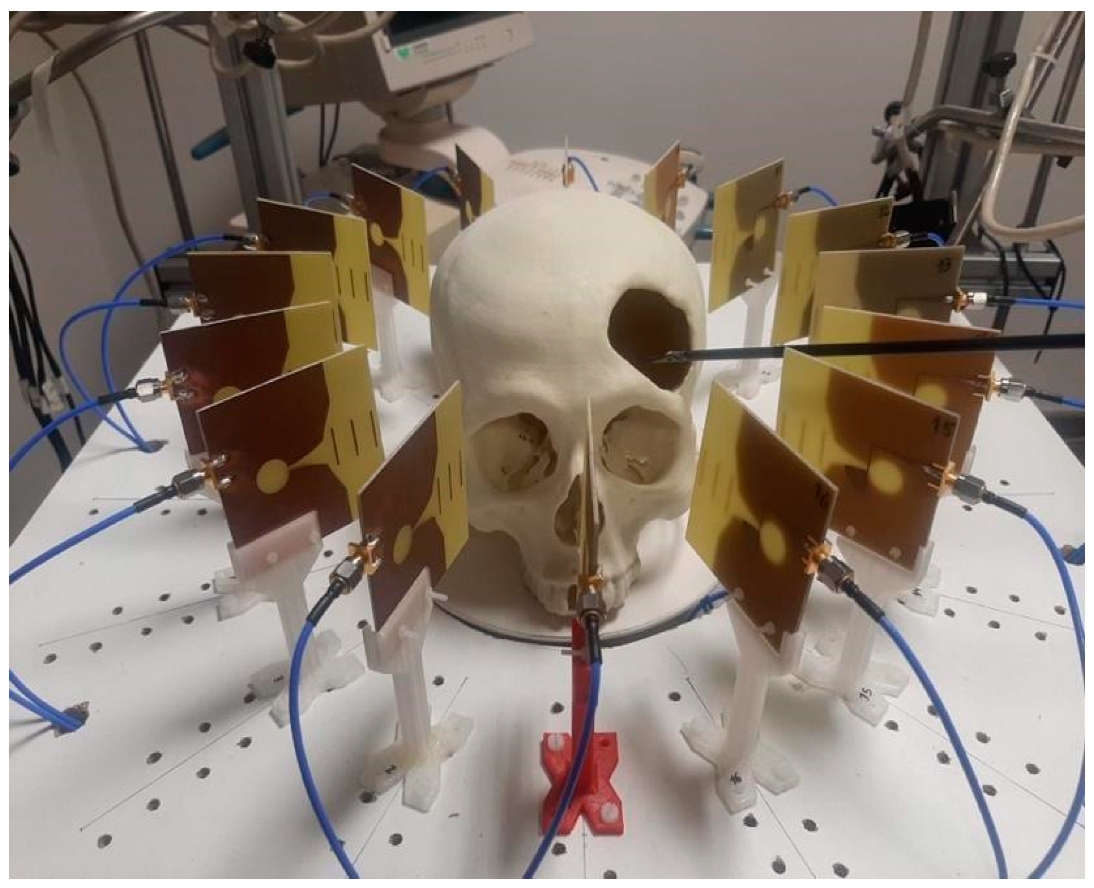
3.1. Experimental Setup
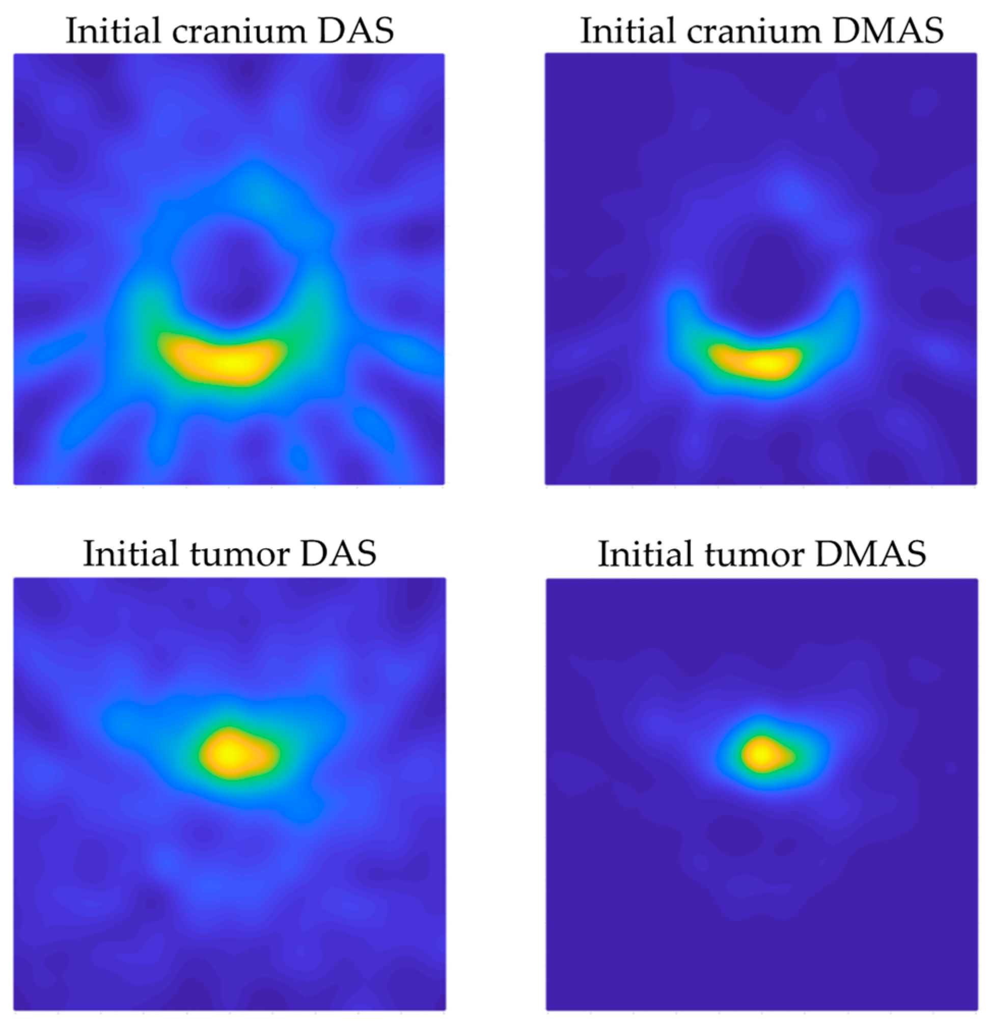
3.2. Image Acquisition
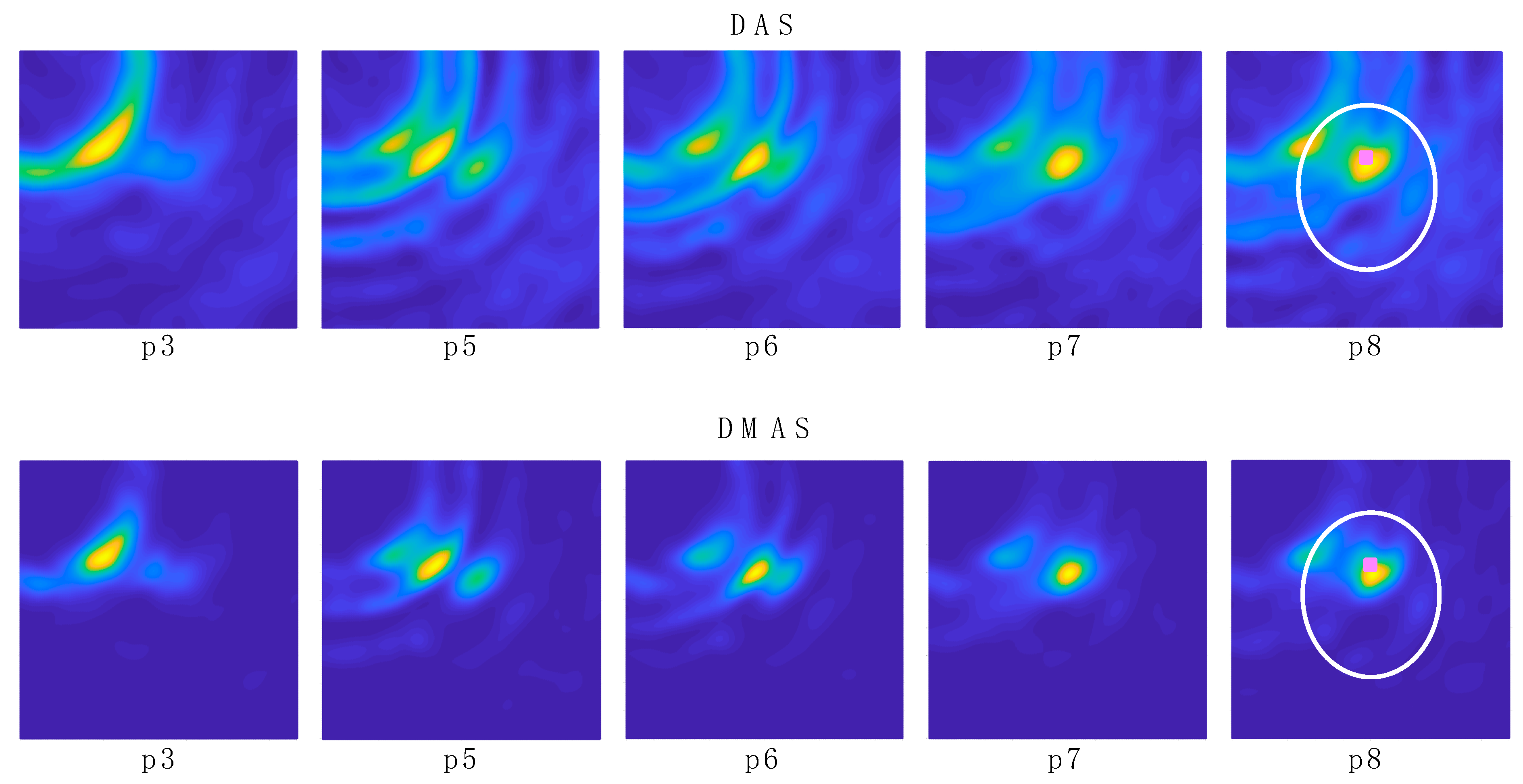
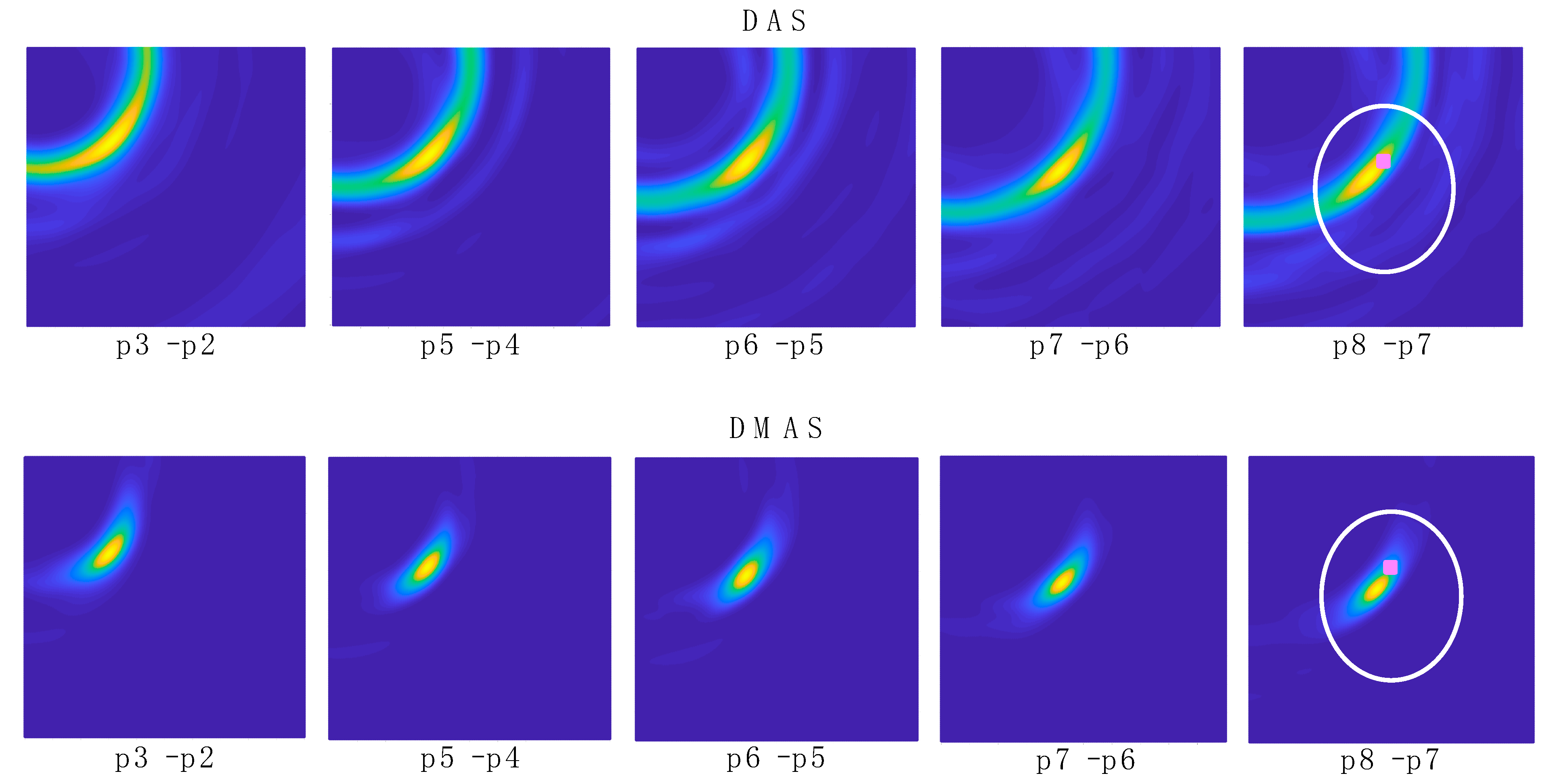
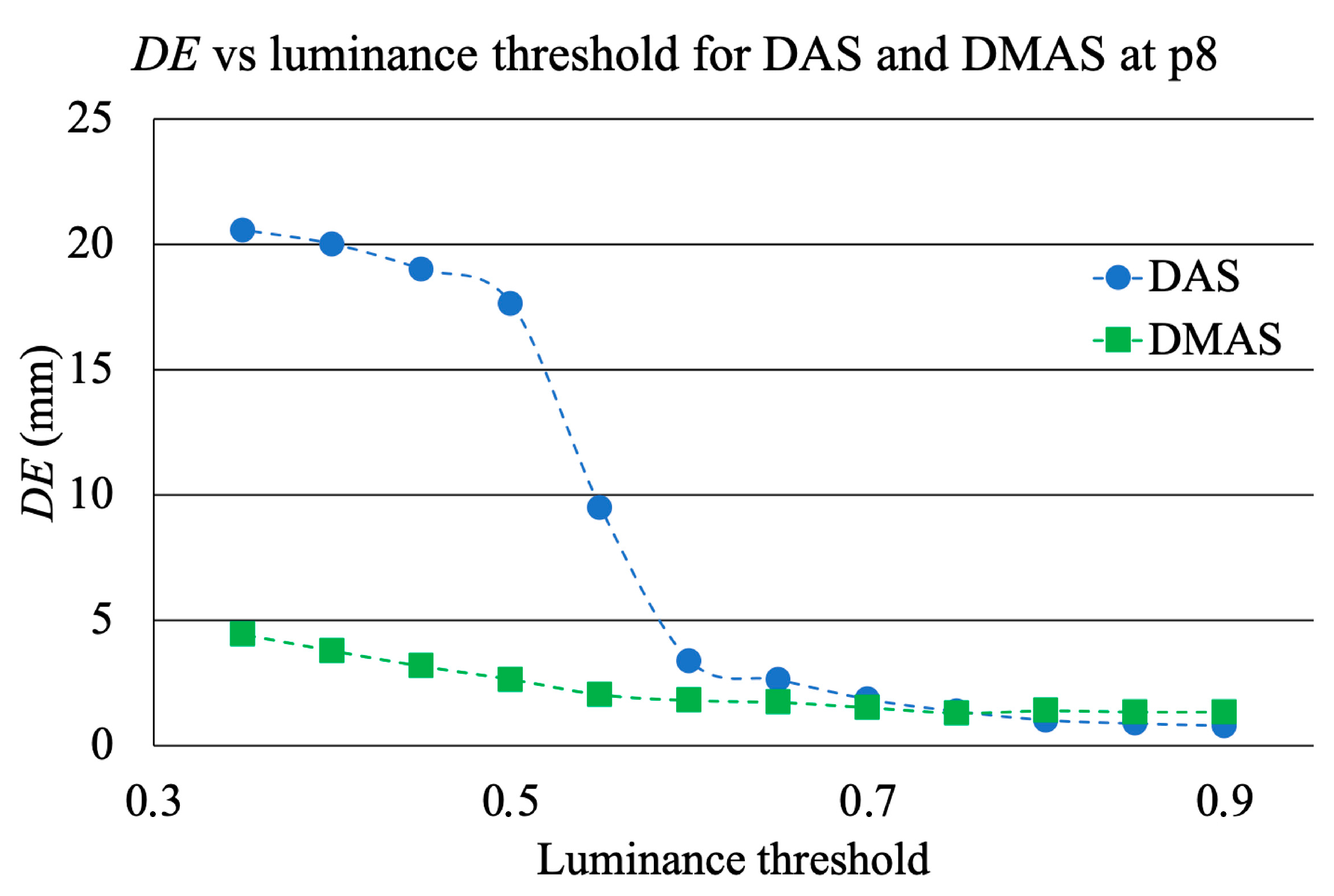
3.3. Data Extraction and Results
4. Discussion
5. Conclusions
Author Contributions
Funding
Conflicts of Interest
References
- Waelkens, P.; van Oosterom, M.N.; van den Berg, N.S.; Navab, N.; van Leeuwen, F.W.B. Surgical navigation: An overview of the state-of-the-art clinical applications. In Radioguided Surgery; Herrmann, K., Nieweg, O., Povoski, S., Eds.; Springer: Cham, Switzerland, 2016; pp. 57–73. [Google Scholar] [CrossRef]
- Chen, L.; Day, T.W.; Tang, W.; John, N.W. Recent developments and future challenges in medical Mixed Reality. In Proceedings of the 2017 IEEE International Symposium on Mixed and Augmented Reality (ISMAR), Nantes, France, 9–13 October 2017; pp. 123–135. [Google Scholar] [CrossRef] [Green Version]
- von Atzigen, M.; Liebmann, F.; Hoch, A.; Bauer, D.E.; Snedeker, J.G.; Farshad, M.; Fürnstahl, P. HoloYolo: A proof-of-concept study for marker-less surgical navigation of spinal rod implants with augmented reality and on-device machine learning. Int. J. Med. Robot. Comput. Assist. Surg. 2021, 17, e2184. [Google Scholar] [CrossRef] [PubMed]
- Sun, Q.; Mai, Y.; Yang, R.; Ji, T.; Jiang, X.; Chen, X. Fast and accurate online calibration of optical see-through head-mounted display for AR-based surgical navigation using Microsoft HoloLens. Int. J. Comput. Assist. Radiol. Surg. 2020, 15, 1907–1919. [Google Scholar] [CrossRef] [PubMed]
- Teatini, A.; Pelanis, E.; Aghayan, D.L.; Kumar, R.P.; Palomar, R.; Fretland, Å.A.; Edwin, B.; Elle, O.J. The effect of intraoperative imaging on surgical navigation for laparoscopic liver resection surgery. Sci. Rep. 2019, 9, 18687. [Google Scholar] [CrossRef] [PubMed]
- Aurand, A.A.; Dufour, J.S.; Marras, W.S. Accuracy map of an optical motion capture system with 42 or 21 cameras in a large measurement volume. J. Biomech. 2017, 58, 237–240. [Google Scholar] [CrossRef] [PubMed]
- Marinetto, E.; García-Mato, D.; García, A.; Martínez, S.; Desco, M.; Pascau, J. Multicamera optical tracker assessment for computer aided surgery applications. IEEE Access 2018, 6, 64359–64370. [Google Scholar] [CrossRef]
- Nafis, C.; Jensen, V.; Beauregard, L.; Anderson, P. Method for estimating dynamic EM tracking accuracy of surgical navigation tools. In Proceedings of the Medical Imaging 2006: Visualization, Image-Guided Procedures, and Display, San Diego, CA, USA, 11–16 February 2006; Cleary, K.R., Galloway, R.L., Jr., Eds.; SPIE: San Diego, CA, USA, 2006; Volume 6141. [Google Scholar] [CrossRef]
- Paydarfar, J.A.; Wu, X.; Halter, R.J. Initial experience with image-guided surgical navigation in transoral surgery. Head Neck 2019, 41, E1–E10. [Google Scholar] [CrossRef] [Green Version]
- Krücker, J.; Xu, S.; Venkatesan, A.; Locklin, J.K.; Amalou, H.; Glossop, N.; Wood, B.J. Clinical utility of real-time fusion guidance for biopsy and ablation. J. Vasc. Interv. Radiol. 2011, 22, 515–524. [Google Scholar] [CrossRef] [Green Version]
- Polaris NDI-Digital. Available online: https://www.ndigital.com/products/polaris-vega/ (accessed on 18 May 2022).
- OptiTrack Motion Capture. Available online: https://optitrack.com (accessed on 18 May 2022).
- Vaccarella, A.; De Momi, E.; Enquobahrie, A.; Ferrigno, G. Unscented Kalman filter based sensor fusion for robust optical and electromagnetic tracking in surgical navigation. IEEE Trans. Instrum. Meas. 2013, 62, 2067–2081. [Google Scholar] [CrossRef]
- Andria, G.; Attivissimo, F.; Di Nisio, A.; Lanzolla, A.M.L.; Ragolia, M.A. Assessment of position repeatability error in an electromagnetic tracking system for surgical navigation. Sensors 2020, 20, 961. [Google Scholar] [CrossRef] [Green Version]
- Wu, X.; Taylor, R.H. A framework for calibration of electromagnetic surgical navigation systems. In Proceedings of the 2003 IEEE/RSJ International Conference on Intelligent Robots and Systems (IROS 2003), Las Vegas, NV, USA, 27–31 October 2003; pp. 547–552. [Google Scholar] [CrossRef]
- Aurora NDI-Digital. Available online: https://www.ndigital.com/products/aurora/ (accessed on 18 May 2022).
- Ma, L.; Zhao, Z.; Zhang, B.; Jiang, W.; Fu, L.; Zhang, X.; Liao, H. Three-dimensional augmented reality surgical navigation with hybrid optical and electromagnetic tracking for distal intramedullary nail interlocking. Int. J. Med. Robot. Comput. Assist. Surg 2018, 14, e1909. [Google Scholar] [CrossRef]
- Chandra, R.; Zhou, H.; Balasingham, I.; Narayanan, R.M. On the opportunities and challenges in microwave medical sensing and imaging. IEEE Trans. Biomed. Eng. 2015, 62, 1667–1682. [Google Scholar] [CrossRef] [PubMed]
- Alibakhshikenari, M.; Virdee, B.S.; Shukla, P.; Parchin, N.O.; Azpilicueta, L.; See, C.H.; Abd-Alhameed, R.A.; Falcone, F.; Huynen, I.; Limiti, E. Metamaterial-inspired antenna array for application in microwave breast imaging systems for tumor detection. IEEE Access 2020, 8, 174667–174678. [Google Scholar] [CrossRef]
- Shao, W.; McCollough, T. Advances in microwave near-field imaging. IEEE Microw. Mag. 2020, 21, 94–119. [Google Scholar] [CrossRef]
- Fass, L. Imaging and cancer: A review. Mol. Oncol. 2008, 2, 115–152. [Google Scholar] [CrossRef] [PubMed]
- Benny, R.; Anjit, T.A.; Mythili, P. An overview of microwave imaging for breast tumor detection. Prog. Electromagn. Res. B 2020, 87, 61–91. [Google Scholar] [CrossRef]
- Mobashsher, A.T.; Bialkowski, K.S.; Abbosh, A.M.; Crozier, S. Design and experimental evaluation of a non-invasive microwave head imaging system for intracranial haemorrhage detection. PLoS ONE 2016, 11, e0152351. [Google Scholar] [CrossRef]
- Yngvesson, K.S.; Korzeniowski, T.L.; Kim, Y.-S.; Kollberg, E.L.; Johansson, J.F. The tapered slot antenna—A new integrated element for millimeter-wave applications. IEEE Trans. Microw. Theory Tech. 1989, 37, 365–374. [Google Scholar] [CrossRef]
- Wu, J.; Zhao, Z.; Nie, Z.; Liu, Q.-H. A printed UWB Vivaldi antenna using stepped connection structure between slotline and tapered patches. IEEE Antennas Wirel. Propag. Lett. 2014, 13, 698–701. [Google Scholar] [CrossRef]
- Martínez-Lozano, A.; Blanco-Angulo, C.; García-Martínez, H.; Gutiérrez-Mazón, R.; Torregrosa-Penalva, G.; Ávila-Navarro, E.; Sabater-Navarro, J.M. UWB-printed rectangular-based monopole antenna for biological tissue analysis. Electronics 2021, 10, 304. [Google Scholar] [CrossRef]
- Hagness, S.C.; Taflove, A.; Bridges, J.E. Two-dimensional FDTD analysis of a pulsed microwave confocal system for breast cancer detection: Fixed-focus and antenna-array sensors. IEEE Trans. Biomed. Eng. 1998, 45, 1470–1479. [Google Scholar] [CrossRef] [Green Version]
- Lim, H.B.; Nhung, N.T.T.; Li, E.-P.; Thang, N.D. Confocal microwave imaging for breast cancer detection: Delay-Multiply-and-Sum image reconstruction algorithm. IEEE Trans. Biomed. Eng. 2008, 55, 1697–1704. [Google Scholar] [CrossRef] [PubMed]
- Jovanovic, D.; Bragard, G.; Picard, D.; Chauvin, S. Mobile telephones: A comparison of radiated power between 3G VoIP calls and 3G VoCS calls. J. Expo. Sci. Environ. Epidemiol. 2015, 25, 80–83. [Google Scholar] [CrossRef] [PubMed]
- Komune, N.; Matsushima, K.; Matsuo, S.; Safavi-Abbasi, S.; Matsumoto, N.; Rhoton, A.L., Jr. The accuracy of an electromagnetic navigation system in lateral skull base approaches. Laryngoscope 2017, 127, 450–459. [Google Scholar] [CrossRef] [PubMed]
- Mohammed, B.J.; Abbosh, A.M.; Mustafa, S.; Ireland, D. Microwave system for head imaging. IEEE Trans. Instrum. Meas. 2014, 63, 117–123. [Google Scholar] [CrossRef]
- Raihan, R.; Bhuiyan, M.S.A.; Hasan, R.R.; Chowdhury, T.; Farhin, R. A wearable microstrip patch antenna for detecting brain cancer. In Proceedings of the 2017 IEEE 2nd International Conference on Signal and Image Processing (ICSIP), Singapore, 4–6 August 2017; pp. 432–436. [Google Scholar] [CrossRef]
- Alagee, R.; Assalemb, A. Brain cancer detection using U-shaped slot VIVALDI antenna and confocal radar based microwave imaging algorithm. Am. Sci. Res. J. Eng. Technol. Sci. 2020, 66, 1–13. [Google Scholar]
- Byrne, D.; Craddock, I.J. Time-domain wideband adaptive beamforming for radar breast imaging. IEEE Trans. Antennas Propag. 2015, 63, 1725–1735. [Google Scholar] [CrossRef]
- Mehranpour, M.; Jarchi, S.; Keshtkar, A.; Ghorbani, A.; Araghi, A.; Yurduseven, O.; Khalily, M. Robust breast cancer imaging based on a Hybrid Artifact Suppression method for early-stage tumor detection. IEEE Access 2020, 8, 206790–206805. [Google Scholar] [CrossRef]


| Positions | DAS | DMAS | Robot | |||
|---|---|---|---|---|---|---|
| x | y | x | y | x | y | |
| Tumor | −0.6342 | 26.1538 | 0.0961 | 26.3117 | — | — |
| p2 | 80.6823 | 0.4284 | 111.0871 | −13.9562 | 90.4000 | 96.2000 |
| p3 | 47.4907 | 47.0544 | 47.4907 | 44.3263 | 67.0000 | 70.8000 |
| p4 | 42.3399 | 37.4496 | 41.8595 | 36.3899 | 58.6000 | 61.7000 |
| p5 | 36.3243 | 32.8501 | 36.1898 | 31.7679 | 45.8000 | 47.9000 |
| p6 | 26.1574 | 25.5000 | 26.1189 | 24.0119 | 29.5000 | 30.2000 |
| p7 | 17.7778 | 17.4735 | 17.8162 | 16.4589 | 19.6000 | 19.5000 |
| p8 | 11.9544 | 10.9576 | 12.4925 | 10.5743 | 11.1000 | 10.4000 |
| Position Range | DAS | DMAS | ||||||
|---|---|---|---|---|---|---|---|---|
| σx | σy | σx | σy | |||||
| p3 to p8 | 8.2593 | 11.5358 | 8.2550 | 11.0136 | 8.2721 | 12.8285 | 8.4759 | 11.5053 |
| p5 to p8 | 3.4465 | 5.3047 | 4.3779 | 6.8422 | 3.3456 | 6.2968 | 4.6237 | 7.0526 |
| p6 to p8 | 1.4368 | 2.0563 | 2.1249 | 2.6289 | 1.2575 | 3.0183 | 2.4299 | 3.1812 |
Publisher’s Note: MDPI stays neutral with regard to jurisdictional claims in published maps and institutional affiliations. |
© 2022 by the authors. Licensee MDPI, Basel, Switzerland. This article is an open access article distributed under the terms and conditions of the Creative Commons Attribution (CC BY) license (https://creativecommons.org/licenses/by/4.0/).
Share and Cite
Blanco-Angulo, C.; Martínez-Lozano, A.; Juan, C.G.; Gutiérrez-Mazón, R.; Arias-Rodríguez, J.; Ávila-Navarro, E.; Sabater-Navarro, J.M. Validation of an RF Image System for Real-Time Tracking Neurosurgical Tools. Sensors 2022, 22, 3845. https://doi.org/10.3390/s22103845
Blanco-Angulo C, Martínez-Lozano A, Juan CG, Gutiérrez-Mazón R, Arias-Rodríguez J, Ávila-Navarro E, Sabater-Navarro JM. Validation of an RF Image System for Real-Time Tracking Neurosurgical Tools. Sensors. 2022; 22(10):3845. https://doi.org/10.3390/s22103845
Chicago/Turabian StyleBlanco-Angulo, Carolina, Andrea Martínez-Lozano, Carlos G. Juan, Roberto Gutiérrez-Mazón, Julia Arias-Rodríguez, Ernesto Ávila-Navarro, and José M. Sabater-Navarro. 2022. "Validation of an RF Image System for Real-Time Tracking Neurosurgical Tools" Sensors 22, no. 10: 3845. https://doi.org/10.3390/s22103845
APA StyleBlanco-Angulo, C., Martínez-Lozano, A., Juan, C. G., Gutiérrez-Mazón, R., Arias-Rodríguez, J., Ávila-Navarro, E., & Sabater-Navarro, J. M. (2022). Validation of an RF Image System for Real-Time Tracking Neurosurgical Tools. Sensors, 22(10), 3845. https://doi.org/10.3390/s22103845