Article

Adaptive Fault-Tolerant Formation Control of Heterogeneous Multi-Agent Systems under Directed Communication Topology

1
College of Automation Engineering, Nanjing University of Aeronautics and Astronautics, Nanjing 211106, China
2
Jiangsu Key Laboratory of Internet of Things and Control Technologies, Nanjing University of Aeronautics and Astronautics, Nanjing 211106, China
*
Author to whom correspondence should be addressed.
Sensors 2022, 22(16), 6212; https://doi.org/10.3390/s22166212
Submission received: 15 July 2022 / Revised: 9 August 2022 / Accepted: 16 August 2022 / Published: 18 August 2022

Abstract

:
This paper investigates the adaptive fault-tolerant formation control scheme for heterogeneous multi-agent systems consisting of unmanned aerial vehicles (UAVs) and unmanned surface vehicles (USVs) with actuator faults, parameter uncertainties and external disturbances under directed communication topology. Firstly, the dynamic models of UAVs and USVs are introduced, and a unified heterogeneous multi-agent system model with actuator faults is established. Then, a distributed fault-tolerant formation controller is proposed for the unified model of UAVs and USVs in the X Y plane by using adaptive updating laws and radial basis function neural network. After that, a decentralized formation-tracking controller is designed for the altitude control system of UAVs. Based on the Lyapunov stability theory, it can be proved that the formation errors and tracking errors are uniformly ultimately bounded which means that the expected time-varying formation is achieved. Finally, a simulation study is given to demonstrate the effectiveness of the proposed scheme.

1. Introduction

In the last three decades, the formation control of multi-agent systems (MASs) has drawn lots of researchers’ attention in both theoretical research and practical applications, such as forest fire monitoring, power grid inspection, search and rescue, and so on [1,2,3,4,5,6]. The purpose of formation control is to form a specific formation to complete the tasks. One of the fundamental problem in MASs is consensus problem. Consensus problems of MASs have been investigated extensively and results have been achieved [7,8,9,10,11,12,13]. Based on the consensus theory, the formation control problem of MASs can be solved. In [14], the output-feedback formation control protocol of tracking a desired trajectory for a set of UAVs is developed. In [15], a distributed time-varying output formation control scheme is introduced for general linear MASs with directed topology. In [16], a distributed leader-following formation control for multiple quadrotors is studied by using nonsmooth backstepping method. In [17], a distributed relative position-based formation control by using backstepping approach is studied for leader–follower MASs.
However, the above results for formation control are used for homogeneous multi-agent systems. In the actual applications, for the heterogeneous multi-agent systems (HMASs) in which each agent may have different structures, dynamics and even the information perceptions and decision-making capabilities are considered. The time-varying formation-containment control for homogeneous and heterogeneous MASs is studied in [18]. In [19], the time-varying output formation-tracking scheme for linear HMASs is developed with directed topologies. In [20], the coherent formation control for HMASs is introduced. The distributed cooperative synchronization control problem for a networked HMASs is developed in [21]. The HMASs can achieve more complex and variable tasks through information interaction. For example, the HMASs consisting of multiple UAVs and USVs have a larger search radius and attack range, which is of great significance in both military and civil fields. Due to the heterogeneous characteristics of UAVs and USVs, as well as the influence of parameter uncertainties and external environment, the air–sea heterogeneous formation faces several important challenges which are shown as follows:
  • UAVs and USVs differ notably in structure, model parameters, and state dimensions. Furthermore, the task changing is random, making it difficult to complete air–sea coordinated formation tasks.
  • During the process of formation, the UAVs and USVs may inevitably be subjected to internal and external uncertainties, such as parameter uncertainties and external disturbances caused by modeling techniques and external environment.
  • Unsatisfactory faults caused by a lot of damage to the actuator of the multiple UAVs and USVs system may affect the tracking performance.
In practical applications, faults may occur in the MASs. Faults may lead to system performance degradation, or even more serious consequences. Fault-tolerant control (FTC) is a useful method that has drawn wide attention [22,23,24,25]. In [26], a distributed adaptive leader-following formation control problem is studied for nonlinear second-order MASs in the presence of actuator faults. The distributed fault-tolerant time-varying formation control scheme for second-order MASs is presented subject to actuator faults in [27]. In [28], the active FTC problem is illustrated for the high-order HMASs with network disconnections and actuator faults. In [29], an adaptive FTC strategy by using a virtual actuator framework is presented for nonlinear HMASs with actuator faults. In addition, external disturbances and parameter uncertainties can also impact the performance of the systems. In [30], the time-varying formation tracking control scheme for the linear MASs is presented with external disturbances under directed graph. In [31], the time-varying anti-disturbance formation control scheme is introduced for nonlinear MASs under switched directed topologies. An adaptive tracking controller by adjusting the coupling weight is designed for the leader–follower linear MASs with external disturbances in [32]. In [33], an internal model approach is studied for the leader-following rendezvous with external disturbances and parameter uncertainties. During the process of formation, unmanned vehicles inevitably suffer from actuator faults, parameter uncertainties, and external disturbances. For example, due to modeling techniques and unpredictable marine environments, USVs are subject to internal and external uncertainties consisting of parameter uncertainties, nonparametric uncertainties, and external disturbances [34]. In addition, the actuator faults and uncertainties in a single vehicle can spread unevenly to neighboring vehicles through the directed communication topology in the process of formation. Hence, it is necessary to study the fault-tolerant formation control for HMASs consisting of multiple UAVs and USVs with parameter uncertainties and external disturbances. Although the research on FTC of MASs has achieved some results, the adaptive fault-tolerant formation control under directed communication topology for air-sea systems is still open, and needs to be further studied.
Motivated by the abovementioned results, this paper presents the adaptive fault-tolerant formation control scheme for multiple UAVs and USVs with actuator faults, parameter uncertainties, and external disturbances under directed communication topology. In order to handle the problems, a unified dynamic model of UAVs and USVs, which includes the X Y plane and Z axis, are presented. To deal with the parameter uncertainties and external disturbances, a distributed fault-tolerant formation controller by combining adaptive control method and the radial basis function neural network is proposed in the X Y plane and a decentralized formation-tracking controller is designed for the altitude control system of UAVs in the Z axis. The main contributions of this paper are summarized as
  • The adaptive fault-tolerant formation control is developed for the HMASs with parameter uncertainties, external disturbances, and actuator faults including loss of effectiveness and bias under directed communication topology. Some existing results have been researched for time-varying formation control, such as [16,34,35,36,37]. However, these results only consider the formation control of single vehicle or the HMASs consisting of a UAV and a USV. In this paper, the fault-tolerant time-varying formation for multiple UAVs and USVs can be achieved.
  • In order to handle parameter uncertainties and external disturbances, the adaptive control method and the radial basis function neural network (RBFNN) are combined to ensure that the formation errors and tracking errors of the closed-loop system are uniformly ultimately bounded.
  • Compared with the works [20,38], in which the height of each UAV is the same and time-invariant, this paper presents a decentralized tracking controller for the altitude control system of UAVs to track the reference signal to meet the requirements of practical tasks.
The rest of this paper is organized as follows. In Section 2, some preliminaries and problem formulation are given. In Section 3, the distributed adaptive fault-tolerant formation control scheme is introduced for multiple UAVs and USVs in the presence of actuator faults, parameter uncertainties and external disturbances. In Section 4, a decentralized formation tracking controller is proposed for the altitude control system of UAVs. In Section 5, a simulation study is given and some conclusions are drawn in Section 6.
Notation 1.
denotes the Euclidean norm. For a matrix A, λ max ( A ) represents the maximum eigenvalue of matrix A, λ 2 ( A ) represents the minimum nonzero eigenvalue, and A F denotes the Frobenius norm of the matrix. Let 1 denote 1 = col { 1 , , 1 } R N .

2. Preliminaries and Problem Formulation

2.1. Graph Theory

Let G = ( V , E ) be a directed graph, in which V = { 1 , 2 , , N } represents the set of nodes and E V × V represents the set of edges. The neighbour set of node i is denoted by N i = { j V | ( j , i ) E } . If there exists a directed path between two arbitrary nodes, the graph G is strongly connected. A = [ a i j ] R N × N denotes the adjacency matrix of G , where a i j = 1 if ( j , i ) E and a i j = 0 otherwise. D = diag { d 1 , d 2 , , d N } denotes the degree matrix of G , where d i = j = 1 N a i j . The Laplacian matrix of G is defined as L = D A .
Lemma 1
([39,40]).If the graph G is strongly connected, the following statements hold.
  • There exists a vector φ = [ φ 1 , φ 2 , , φ N ] with i = 1 N φ i = 1 and φ i > 0 , such that φ L = 0 .
  • Define a symmetric matrix L ¯ = Ψ L + L Ψ with Ψ = diag { φ 1 , φ 2 , , φ N } . Then L ¯ can be treated as Laplacian matrix associated with an undirected graph. Let ϖ ( t ) R N × 1 , the following inequality holds
    min ϖ ( t ) L ¯ ϖ ( t ) > λ 2 ( L ¯ ) N ϖ ( t ) ϖ ( t ) .

2.2. Problem Formulation

In this subsection, the HMASs consisting of M UAVs and N M USVs are considered. The dynamic models of the UAVs and USVs are given firstly. Based on them, a unified dynamic model for the HMASs is demonstrated. For convenience, let Π 1 = { 1 , 2 , , M } , Π 2 = { M + 1 , M + 2 , , N } and Π = Π 1 Π 2 .
Unmanned aerial vehicle model.The structure of the quadrotor UAV is shown in Figure 1. The dynamic model of the i-th ( i Π 1 ) quadrotor UAV is given as [41]
p ¨ a i x = ( cos ϕ i sin θ i cos ψ i + sin ϕ i sin ψ i ) u p i m a i d i x p ˙ a i x m a i + Δ a i x , p ¨ a i y = ( cos ϕ i sin θ i sin ψ i + sin ϕ i cos ψ i ) u p i m a i d i y p ˙ a i y m a i + Δ a i y , p ¨ a i z = ( cos θ i cos ϕ i ) u p i m a i d i z p ˙ a i z m a i g + Δ a i z ,
ϕ ¨ i = θ ˙ i ψ ˙ i J a y J a z J a x J a r J a x θ ˙ i d ¯ i + τ ϕ i J a x d i ϕ ϕ ˙ i J a x , θ ¨ i = ϕ ˙ i ψ ˙ i J a z J a x J a y J a r J a y ϕ ˙ i d ¯ i + τ θ i J a y d i θ θ ˙ i J a y , ψ ¨ i = ϕ ˙ i θ ˙ i J a x J a y J a z + τ ψ i J a z d i ψ ψ ˙ i J a z ,
where [ p a i x , p a i y , p a i z ] denotes the position state, [ ϕ i , θ i , ψ i ] denotes the attitude state, u p i denotes the control thrust of the quadrotor, τ ϕ i , τ θ i , τ ψ i denote the three control torques of the quadrotor, m a i is the mass of the quadrotor UAV, g is the gravitational acceleration, d ¯ i denotes the overall residual rotor angle, d i x , d i y , d i z , d i ϕ , d i θ , d i ψ denote the translational drag coefficients, J a x , J a y , J a z are the moments of the inertia, J a r is the moment of rotor’s inertia, Δ a i x , Δ a i y , Δ a i z denote the external disturbances encountered by the quadrotor UAV.
From the dynamic model (1) and (2), we can found that the motion of the quadrotor consists of translational dynamics with respect to positions and rotational dynamics with respect to angles. Our formation goal is to locate the center of mass in a predefined position, while the rotational dynamics can be stabilized separately. Hence, the position dynamics of the i-th ( i Π 1 ) UAV based on (1) can be rewritten as
p ¨ a i = g a i u a i + f a i + Δ a i ,
where p a i = [ p a i x , p a i y , p a i z ] denotes the position of the i-th UAV, f a i = [ d i x p ˙ a i x / m a i , d i y p ˙ a i y / m a i , d i z p ˙ a i z / m a i g ] , g a i = diag { 1 / m a i , 1 / m a i , 1 / m a i } , Δ a i = [ Δ a i x , Δ a i y , Δ a i z ] , u a i = [ u a i x , u a i y , u a i z ] is the new control signal which is given as [42]
u a i x = ( cos ϕ i sin θ i cos ψ i + sin ϕ i sin ψ i ) u p i , u a i y = ( cos ϕ i sin θ i sin ψ i + sin ϕ i cos ψ i ) u p i , u a i z = ( cos θ i cos ϕ i ) u p i .
Unmanned surface vehicle model. The kinematic and dynamic equation of the i-th ( i Π 2 ) USV in the horizontal plane is described as [35]
x ˙ s i = μ s i cos ψ s i ν s i sin ψ s i , y ˙ s i = μ s i sin ψ s i + ν s i cos ψ s i , ψ ˙ s i = r s i ,
μ ˙ s i = f μ s i ( α i ) + 1 m μ s i ( τ μ s i f + w μ s i ) , ν ˙ s i = f ν s i ( α i ) + 1 m ν s i w ν s i , r ˙ s i = f r s i ( α i ) + 1 m r s i ( τ r s i f + w r s i ) ,
and
f μ s i ( α i ) = 1 m μ s i m ν s i ν s i r s i d μ s i μ s i d μ s i 1 | μ s i | μ s i , f ν s i ( α i ) = 1 m ν s i m μ s i μ s i r s i d ν s i ν s i d ν s i 1 | ν s i | ν s i , f r s i ( α i ) = 1 m r s i m μ s i m ν s i μ s i ν s i d r s i r s i d r s i 1 | r s i | r s i ,
where ( x s i , y s i ) is the position of the i-th USV; ψ s i is the yaw angle of the i-th USV; α i = [ μ s i , ν s i , r s i ] are the surge, sway, and yaw velocity, respectively; m μ s i , m ν s i , m r u s i are the inertial mass; f μ s i ( α i ) , f ν s i ( α i ) , f r s i ( α i ) are the nonlinear dynamics consisting of the unmodeled hydrodynamics and Coriolis forces; τ μ s i f and τ r s i f are the surge force and the yaw moment; and w μ s i , w ν s i , w r s i are the bounded disturbances caused by waves, wind, and ocean currents.
Since the motion model of the USVs described by (4) and (5) is underactuated, a hand position approach is used to deal with it. We define the front point ( p s i x , p s i y ) of the USVs as the hand point which can be formulated as
p s i x = x s i + L s i cos ψ s i , p s i y = y s i + L s i sin ψ s i ,
where L s i is the distance between the actual position ( x s i , y s i ) and the new defined hand point ( p s i x , p s i y ) , which is shown in Figure 2.
By taking the second derivative of (7), one can obtain
p ¨ s i x = μ ˙ s i cos ψ s i ( ν ˙ s i + L s i r ˙ s i ) sin ψ s i μ s i r s i sin ψ s i ( ν s i r s i + L s i r s i 2 ) cos ψ s i , p ¨ s i y = μ ˙ s i sin ψ s i ( ν ˙ s i + L s i r ˙ s i ) cos ψ s i + μ s i r s i cos ψ s i ( ν s i r s i + L s i r s i 2 ) sin ψ s i ,
Substituting (6) into (8) yields that
p ¨ s i x = f s i x ( β ) + cos ψ s i m μ s i τ μ f L s i sin ψ s i m r s i τ r f + w d i x , p ¨ s i y = f s i y ( β ) + sin ψ s i m μ s i τ μ f + L s i cos ψ s i m r s i τ r f + w d i y ,
where
f s i x ( β ) = f μ ( α ) cos ψ s i ( f ν ( α ) + L s i f r ( α ) ) sin ψ s i μ s i r s i sin ψ s i ( ν s i r s i + L s i r s i 2 ) cos ψ s i , f s i y ( β ) = f μ ( α ) sin ψ s i + ( f ν ( α ) + L s i f r ( α ) ) cos ψ s i + μ s i r s i cos ψ s i ( ν s i r s i + L s i r s i 2 ) sin ψ s i ,
and
w d i x ( β ) = w μ s i m μ s i cos ψ s i ( w ν s i m μ s i + L s i w r s i m r s i ) sin ψ s i , w d i y ( β ) = w μ s i m μ s i sin ψ s i + ( w ν s i m μ s i + L s i w r s i m r s i ) cos ψ s i ,
with β = [ μ s i , ν s i , r s i , ψ s i ] .
Based on (9), the position dynamics of the i-th ( i Π 2 ) USV can be described as
p ¨ s i = f s i x y + Ω s i ( ψ s i ) ϖ s i u s i + w d i x y ,
where p s i = [ p s i x , p s i y ] is the position of the i-th ( i Π 2 ) USV, f s i x y = [ f s i x , f s i y ] , Ω s i ( ψ s i ) = [ cos ψ s i , sin ψ s i ; sin ψ s i , cos ψ s i ] , u s i = [ τ μ , τ r ] , ϖ s i = diag { 1 / m μ s i , L s i / m r s i } , w d i x y = [ w d i x , w d i y ] .
Actuator fault model.The actuator fault model for the h-th actuator of the i-th ( i Π ) HMASs is given as
u i h F = ρ i h u i h + u i h b ,
where u i h F is the actual actuation input, u i h is the applied control signal to be designed, 0 < ρ i h 1 is the unknown effectiveness factor and u i h b represents the unknown bias. For the actuator fault model (13), ρ i h = 1 and u i h b = 0 denote that there is no fault; 0 < ρ i h < 1 and u i h b = 0 denote the loss of effectiveness fault; ρ i h = 0 and u i h b 0 denote bias fault; 0 < ρ i h < 1 and u i h b 0 denote both loss of effectiveness and bias faults.
From (13), the fault model for all actuators can be described as
u i F = ρ i u i + u i b , i Π ,
where ρ i = diag { ρ i 1 , ρ i 2 , , ρ i n } and u i b = [ u i b 1 , u i b 2 , , u i b n ] with n representing the dimension of the control input signal.
Unified model. The UAV model with actuator faults (14) in the X Y plane can be rewritten as
x ˙ a i 1 = x a i 2 , x ˙ a i 2 = f a i x y + g a i x y ( ρ a i u a i x y + u a i b ) + Δ a i x y = F a i x y + G a i x y u a i x y + Δ a i x y ,
where x a i 1 = [ p a i x , p a i y ] is the position of the i-th UAV in the X Y plane, u a i x y = [ u a i x , u a i y ] , g a i x y = diag { 1 / m a i , 1 / m a i } , f a i x y = [ d i x p ˙ a i x / m a i , d i y p ˙ a i y / m a i ] , F a i x y = f a i x y + g a i x y u a i b , G a i x y = g a i x y ρ a i , ρ a i = diag { ρ a i x , ρ a i y } denotes the effectiveness factor, u a i b = [ u a i b x , u a i b y ] denotes the bias, Δ a i x y = [ Δ a i x , Δ a i y ] .
Similarly, the UAV model with actuator faults (14) in the Z axis can be rewritten as
p ˙ a i z = v a i z , v ˙ a i z = f a i z + 1 m a i ( ρ a i z u a i z + u a i b z ) + Δ a i z = F a i z + G a i z u a i z + Δ a i z ,
where p a i z is the altitude of the i-th UAV, v a i z is the velocity of the i-th UAV in the Z axis, f a i z = d i z p ˙ a i z / m a i g , ρ a i z is the effectiveness factor, u a i b z is the bias, F a i z = f a i z + u a i b z / m a i , G a i z = ρ a i / m a i .
The USV model with actuator faults (14) can be rewritten as
x ˙ s i 1 = x s i 2 , x ˙ s i 2 = f s i x y + g s i ( ρ s i u s i + u s i b ) + w d i x y = F s i + G s i u s i + w d i x y ,
where x s i 1 = p s i , ρ s i = diag { ρ s i x , ρ s i y } is the effectiveness factor, u s i b = [ u s i b x , u s i b y ] is the bias, g s i = Ω s i ( ψ s i ) ϖ s i , F s i = f s i x y + g s i u s i b , G s i = g s i ρ s i .
Combining (15) and (17), the unified model of UAVs and USVs in the X Y plane can be obtained
x ˙ i 1 = x i 2 , x ˙ i 2 = F x i + G x i u x i + Δ x i ,
where x i 1 = x a i 1 R 2 , x i 2 = x a i 2 R 2 are the position and velocity of the i-th ( i Π 1 ) UAV in the X Y plane, F x i = F a i x y , G x i = G a i x y , Δ x i = Δ a i x y , u x i = u a i x y ; x i 1 = x s i 1 R 2 , x i 2 = x s i 2 R 2 are the position and velocity of the i-th ( i Π 2 ) USV, F x i = F s i , G x i = G s i , Δ x i = w d i x y , u x i = u s i .
Hence, we are under the situation to design the fault-tolerant time-varying formation control scheme for the HMASs consisting of multiple UAVs and USVs in the presence of unknown actuator faults, parameter uncertainties and external disturbances under directed topology.
Remark 1.
In the inertial frame O X Y Z , the USVs only move in the X Y plane. The UAVs move in three-dimensional space, but their motion in the Z axis can be decoupled from that in the X Y plane. Hence, the height of the UAVs can be controlled independently. Therefore, the fault-tolerant time-varying formation control for multiple UAVs and USVs is considered in the X Y plane. At the same time, the formation-tracking controller is designed for the UAVs so that the height of the UAVs can track the reference signal. In this way, the fault-tolerant time-varying formation control for multiple UAVs and USVs can be achieved.
Assumption 1.
The effectiveness factor ρ i h and bias u i h b are unknown but bounded. There exist positive constants ρ ̲ i h , ρ ¯ i h and u ¯ i h b satisfying 0 < ρ ̲ i h ρ i h ρ ¯ i h 1 and u i h b u ¯ i h b , respectively.
Assumption 2.
The aerodynamic drag coefficients d i x , d i y and d i z are unknown but bounded.
Assumption 3.
The external disturbances Δ a i x , Δ a i y , Δ a i z encountered by the quadrotor UAV are bounded and satisfying Δ a i x Δ ¯ a i x , Δ a i y Δ ¯ a i y , Δ a i z Δ ¯ a i z , where Δ ¯ a i x , Δ ¯ a i y and Δ ¯ a i z are unknown positive constants.
Assumption 4.
The external disturbances w μ s i , w ν s i , w r s i encountered by the USV are bounded and satisfying w μ s i w ¯ μ s i , w ν s i w ¯ ν s i , w r s i w ¯ r s i , where w ¯ μ s i , w ¯ ν s i and w ¯ r s i are unknown positive constants.
Assumption 5.
In (4), the sway velocity ν s i of the underactuated USV is passively-bounded.
Remark 2.
Assumption 1 is standard to handle the actuator faults in the existing literature [43,44]. Due to the unpredictable aerodynamics produced by the complex operation environment, it is difficult to obtain accurate system parameters, so Assumption 2 is reasonable and realistic. Since UAVs and USVs will not be used under extreme whether conditions, Assumptions 3 and 4 are also reasonable. Superficially, Assumption 5 seems to be restrictive. However, it is easy to verify that Assumption 5 is always satisfied in most practical applications of the USVs [45].

2.3. Radial Basis Function Neural Network

Since the radial basis function neural network can approximate any continuous function with arbitrary precision, in this paper, the RBFNN is used to approximate the nonlinear function. The RBFNN can be expressed as
f ( Z ) = θ * w ( Z ) + ϵ ( Z ) , Z Ω Z ,
where f ( Z ) is a smooth nonlinear function, Z = [ Z 1 , Z 2 , , Z n ] Ω Z R n denotes the input vector, w ( Z ) = [ w 1 ( Z ) , w 2 ( Z ) , , w p ( Z ) ] R p is the basis function vector, p is the number of the RBFNN nodes. ϵ ( Z ) is the approximation error, bounded by ϵ ( Z ) ϵ ¯ . θ * = [ θ 1 , θ 2 , , θ p ] R p is the ideal weighting vector, which is denoted as
θ * = arg min θ R p { sup Z Ω Z | f ( Z ) θ w ( Z ) | } ,
where θ denotes the weighting vector.

2.4. Control Objective

The control objective of this paper is to design an adaptive fault-tolerant formation control scheme for multiple UAVs and USVs (16) and (18) to achieve the time-varying formation of the HMASs in the presence of unknown actuator faults, parameter uncertainties and external disturbances under directed topology, that is, for any given bounded initial states,
lim t ( x i 1 h i 1 ) ( x j 1 h j 1 ) χ 1 , lim t ( x i 2 h i 2 ) χ 2 , i Π , lim t p a i z c i p χ 3 , lim t v a i z c i v χ 4 , i Π 1 ,
where χ 1 , χ 2 , χ 3 and χ 4 are small enough positive constants, h ( t ) = [ h 1 ( t ) , h 2 ( t ) , , h N ( t ) ] is the desired time-varying formation with h i ( t ) = [ h i 1 ( t ) , h i 2 ( t ) ] being piecewise continuously differentiable. h i 1 ( t ) and h i 2 ( t ) are the position and velocity, respectively. c i p and c i v are the desired height and velocity reference signal, respectively.

3. Distributed Fault-Tolerant Formation Control Scheme and Performance Analysis

In this section, a distributed fault-tolerant formation control scheme is designed to achieve the time-varying formation control of HMASs composed of UAVs and USVs with actuator faults, parameter uncertainties and external disturbances under directed topology in the X Y plane.

3.1. Distributed Fault-Tolerant Formation Controller Design

Define a synchronization formation error signal for each vehicle as
e i = j = 1 N a i j x i 1 h i 1 ( x j 1 h j 2 ) + x i 2 h i 2 , i Π .
Let z i = x i 1 h i 1 and s i = x i 2 h i 2 . Then the time derivative of z i and s i can be written as
z ˙ i = x i 2 + h i 2 h ˙ i 1 ,
s ˙ i = F x i + G x i u x i + Δ x i h ˙ i 2 .
Let z ˜ i = z i j = 1 N φ j z j , where φ j is given in Lemma 1. Let z ˜ = [ z ˜ 1 , z ˜ 2 , , z ˜ N ] , e = [ e 1 , e 2 , , e N ] . If the feasibility condition h i 2 h ˙ i 1 = 0 is satisfied, then the HMASs (22) and (23) based on the definitions of z ˜ and e can be written as
z ˜ ˙ = ( I N 1 φ ) e L z ˜ ,
e ˙ = L e L 2 z ˜ + F x + G x u x + Δ x h ˙ 2 ,
where F x = [ F x 1 , F x 2 , , F x N ] , G x = diag { G x 1 , G x 2 , , G x N } , h ˙ 2 = [ h ˙ 12 , h ˙ 22 , , h ˙ N 2 ] , Δ x = [ Δ x 1 , Δ x 2 , , Δ x N ] , u x = [ u x 1 , u x 2 , , u x N ] .
The control input of the HMASs and the adaptive laws are developed as
u x i = G ^ x i 1 ( δ i e i e i κ ^ i 11 ω i 1 ω i 1 2 ς i 1 2 e i κ ^ i 12 2 ς i 2 2 + h ˙ i 2 ) ,
κ ^ ˙ i 11 = ι 11 ( k 11 κ ^ i 11 + e i e i ω i 1 ω i 1 2 ς i 1 2 ) ,
κ ^ ˙ i 12 = ι 12 ( k 12 κ ^ i 12 + e i e i 2 ς i 2 2 ) ,
G ^ ˙ x i = Proj [ G ̲ x i , G ¯ x i ] { P } = 0 , if G ^ x i = G ¯ x i and P 0 or G ^ x i = G ̲ x i and P 0 , P , otherwise ,
where P = ι 13 ( k 13 G ^ x i + e i u x i ) , G ̲ x i and G ¯ x i are the lower bound and upper bound of the parameter G x i , respectively, δ i , k 11 , k 12 , k 13 , ι 11 , ι 12 , ι 13 , ς i 1 , ς i 2 are positive parameters to be designed.
The schematic of the control system is illustrated in Figure 3.

3.2. Performance Analysis

The performance of the time-varying formation error system is given as follows.
Theorem 1.
Consider a heterogeneous multi-agent system (18). Suppose that Assumptions 1–5 hold and the feasibility condition h i 2 h ˙ i 1 = 0 of the time-varying formation is satisfied, the fault-tolerant control scheme is designed as (26) and the adaptive laws are developed as (27)–(29), then the time-varying formation errors z ˜ and e in the X Y plane are uniformly ultimately bounded.
Proof of Theorem 1.
Consider the following Lyapunov candidate function
V = z ˜ Ψ z ˜ + 1 2 e e + i = 1 N κ ˜ i 11 2 2 ι 11 + i = 1 N κ ˜ i 12 2 2 ι 12 + i = 1 N Tr ( G ˜ x i G ˜ x i ) 2 ι 13 ,
where κ ˜ i 11 = κ i 11 κ ^ i 11 , κ ˜ i 12 = κ i 12 κ ^ i 12 and G ˜ x i = G x i G ^ x i .
The time derivative of (30) is given as
V ˙ e L e e L 2 z ˜ + 2 z ˜ Ψ φ φ e z ˜ L ¯ z ˜ + i = 1 N e i F x i + i = 1 N e i ( G ˜ x i + G ^ x i ) u x i i = 1 N e i h ˙ i 2 + i = 1 N e i Δ x i + i = 1 N κ ˜ i 11 κ ˜ ˙ i 11 ι 11 + i = 1 N κ ˜ i 12 κ ˜ ˙ i 12 ι 12 + i = 1 N Tr ( G ˜ x i G ˜ ˙ x i ) ι 13 .
Substituting the control input (26) into (31), we can obtain
V ˙ e L e e L 2 z ˜ + 2 z ˜ Ψ φ φ e z ˜ L ¯ z ˜ i = 1 N δ i e i e i + i = 1 N e i F x i i = 1 N e i e i κ ^ i 11 ω i 1 ω i 1 2 ς i 1 2 i = 1 N e i e i κ ^ i 12 2 ς i 2 2 + i = 1 N e i G ˜ x i u x i + i = 1 N e i Δ x i + i = 1 N κ ˜ i 11 κ ˜ ˙ i 11 ι 11 + i = 1 N κ ˜ i 12 κ ˜ ˙ i 12 ι 12 + i = 1 N Tr ( G ˜ x i G ˜ ˙ x i ) ι 13 .
Then, the RBFNN is used to approximate the unknown nonlinear function F x i , which is shown as
F x i = θ i 1 * ω i 1 + ϵ i 1 ,
where ϵ i 1 ϵ ¯ i 1 .
In terms of Young’s inequality, we can obtain
e i θ i 1 * ω i 1 e i e i κ i 11 ω i 1 ω i 1 2 ς i 1 2 + ς i 1 2 2 ,
e i ( ϵ i 1 + Δ x i ) e i e i κ i 12 2 ς i 2 2 + ς i 2 2 2 ,
where κ i 11 = θ i 1 * θ i 1 * and κ i 12 = ( ϵ ¯ i 1 + Δ ¯ x i ) ( ϵ ¯ i 1 + Δ ¯ x i ) .
Substituting (34) and (35) into (32), we can obtain
V ˙ e L e e L 2 z ˜ + 2 z ˜ Ψ φ φ e z ˜ L ¯ z ˜ i = 1 N δ i e i e i + i = 1 N e i e i κ i 11 ω i 1 ω i 1 2 ς i 1 2 + i = 1 N e i e i κ i 12 2 ς i 2 2 i = 1 N e i e i κ ^ i 11 ω i 1 ω i 1 2 ς i 1 2 i = 1 N e i e i κ ^ i 12 2 ς i 2 2 i = 1 N κ ˜ i 1 k 11 κ ^ i 11 + e i e i ω i 1 ω i 1 2 ς i 1 2 + i = 1 N e i G ˜ x i u x i i = 1 N κ ˜ i 2 k 12 κ ^ i 12 + e i e i 2 ς i 2 2 i = 1 N Tr G ˜ x i k 13 G ^ x i + e i u x i + i = 1 N ς i 1 2 2 + i = 1 N ς i 2 2 2 e T L e e T L 2 z ˜ + 2 z ˜ Ψ φ φ e z ˜ L ¯ z ˜ i = 1 N δ i e i e i i = 1 N k 11 2 κ ˜ i 11 2 i = 1 N k 12 2 κ ˜ i 12 2 i = 1 N k 13 2 G ˜ x i F 2 + i = 1 N k 11 2 κ i 11 2 + i = 1 N k 12 2 κ i 12 2 + i = 1 N k 13 2 G x i F 2 + i = 1 N ς i 1 2 2 + i = 1 N ς i 2 2 2 .
According to Lemma 1, we can obtain
z ˜ L ¯ z ˜ λ 2 ( L ¯ ) N z ˜ 2 .
In terms of Young’s inequality, we can obtain
e L 2 z ˜ λ max 2 ( L ) e z ˜ N λ max 4 ( L ) λ 2 ( L ¯ ) e 2 + λ 2 ( L ¯ ) 4 N z ˜ 2 ,
2 z ˜ Ψ φ φ e 2 e z ˜ 4 N λ 2 ( L ¯ ) e 2 + λ 2 ( L ¯ ) 4 N z ˜ 2 .
Substituting (37)–(39) into (36) yields that
V ˙ δ λ max ( L ) N ( λ max 4 ( L ) + 4 ) λ 2 ( L ¯ ) e 2 λ 2 ( L ¯ ) 2 N z ˜ 2 i = 1 N k 11 2 κ ˜ i 11 2 i = 1 N k 12 2 κ ˜ i 12 2 i = 1 N k 13 2 G ˜ x i F 2 + i = 1 N k 11 2 κ i 11 2 + i = 1 N k 12 2 κ i 12 2 + i = 1 N k 13 2 G x i F 2 + i = 1 N ς i 1 2 2 + i = 1 N ς i 1 2 2 ϱ V + μ ,
where δ = min { δ 1 , δ 2 , , δ N } , ϱ = min { 2 ( δ λ max ( L ) N ( λ max 4 ( L ) + 4 ) λ 2 ( L ¯ ) ) , λ 2 ( L ¯ ) 2 N , ι 11 k 11 , ι 12 k 12 , ι 13 k 13 } > 0 , μ = 1 2 i = 1 N ( k 11 κ i 11 2 + k 12 κ i 12 2 + k 13 G x i F 2 + ς i 1 2 + ς i 2 2 ) .
In terms of the boundedness theorem, the time-varying formation errors z ˜ and e are uniformly ultimately bounded. Recalling the definition of z ˜ i , s i and e i , we can conclude that s i is uniformly ultimately bounded. According to the control objective, the time-varying formation of the HMASs in the X Y plane is achieved. This completes the proof. □
Remark 3.
The time-varying formation feasibility condition h i 2 h ˙ i 1 = 0 indicates that there exists a constraint on the formation that can be achieved. Due to their dynamic limitations, the HMASs are unable to achieve any formations. Therefore, it is necessary to judge whether the feasibility condition is met when a formation is given. If the condition is met, the pre-designed time-varying formation can be achieved.

4. Decentralized Formation Controller Design and Performance Analysis

In this section, a decentralized formation controller is designed to achieve the height tracking control of UAVs in the Z axis.

4.1. Decentralized Formation Controller Design

The altitude error system is defined as
e i z p = p a i z c i p ,
e i z v = v a i z c i v ,
where c i p is the desired position signal and c i v is the desired velocity signal.
The formation tracking control input and adaptive laws are designed as
u a i z = G ^ a i z 1 ( σ i e i ζ e i ζ κ ^ i 21 ω i 2 ω i 2 2 ς i 3 2 e i ζ κ ^ i 22 2 ς i 4 2 + c ˙ i v k i ζ e i z v ) ,
κ ^ ˙ i 21 = ι 21 ( k 21 κ ^ i 21 + e i ζ e i ζ ω i 2 ω i 2 2 ς i 3 2 ) ,
κ ^ ˙ i 22 = ι 22 ( k 22 κ ^ i 22 + e i ζ e i ζ 2 ς i 4 2 ) ,
G ^ ˙ a i z = Proj [ G ̲ a i z , G ¯ a i z ] { S } = 0 , if G ^ a i z = G ¯ a i z and S 0 or G ^ a i z = G ̲ a i z and S 0 , S , otherwise ,
where S = ι 23 ( k 23 G ^ a i z + e i ζ u a i z ) , G ̲ a i z and G ¯ a i z are the lower bound and upper bound of the parameter G x i , respectively, where σ i , k 21 , k 22 , k 23 , k i ζ , ι 21 , ι 22 , ι 23 , ς i 3 , ς i 4 are positive parameters to be designed.

4.2. Performance Analysis

The performance of the altitude error system is given as follows.
Theorem 2.
Consider the UAVs’ altitude control system (16). Suppose that Assumptions 1–3 hold and the feasibility condition c i v c ˙ i p = 0 is satisfied, the formation tracking control scheme is designed as (43) and the adaptive laws are developed as (44)–(46), then the UAVs’ altitude trajectory can track the reference signal and the tracking error e i z p is uniformly ultimately bounded.
Proof of Theorem 2.
If the feasibility condition c i v c ˙ i p = 0 is satisfied, then the time derivative of the altitude error system (41) and (42) can be written as
e ˙ i z p = e i z v ,
e ˙ i z v = F a i z + G a i z u a i z + Δ a i z c ˙ i v .
In the system (47), e i z v can be regarded as the virtual control input. By designing the virtual control input ζ i = k i ζ e i z p , the stability of the system (47) can be ensured.
Consider a positive Lyapunov function as
V i z p = 1 2 e i z p e i z p .
The time derivative of (50) is given by
V ˙ i z p = k i ζ e i z p e i z p .
Define a new error as
e i ζ = e i z v ζ i .
Taking the time derivative of (51) and substituting the control input (43) into it, we can obtain
e ˙ i ζ = σ i e i ζ + F a i z + Δ a i z + G ˜ a i z u a i z e i ζ κ ^ i 21 ω i 2 ω i 2 2 ς i 3 2 e i ζ κ ^ i 22 2 ς i 4 2 .
Consider the following Lyapunov candidate function
V z = i = 1 N V i z ,
where V i z is given as
V i z = 1 2 e i z p e i z p + 1 2 e i ζ e i ζ + κ ˜ i 21 2 2 ι 21 + κ ˜ i 22 2 2 ι 22 + Tr ( G ˜ a i z G ˜ a i z ) 2 ι 23 ,
with κ ˜ i 21 = κ i 21 κ ^ i 21 , κ ˜ i 22 = κ i 22 κ ^ i 22 and G ˜ a i z = G a i z G ^ a i z .
Taking the time derivative of (54) yields that
V ˙ i z k i ζ e i z p e i z p σ i e i ζ e i ζ + e i ζ F a i z + e i ζ Δ a i z + e i ζ G ˜ a i z u a i z e i ζ e i ζ κ ^ i 21 ω i 2 ω i 2 2 ς i 3 2 e i ζ e i ζ κ ^ i 22 2 ς i 4 2 + κ ˜ i 21 κ ˜ ˙ i 21 ι 21 + κ ˜ i 22 κ ˜ ˙ i 22 ι 22 + Tr ( G ˜ a i z G ˜ ˙ a i z ) ι 23 .
Similarly, the RBFNN is used to approximate the unknown nonlinear function F a i z , which is shown as
F a i z = θ i 2 * ω i 2 + ϵ i 2 ,
where ϵ i 2 ϵ ¯ i 2 .
In terms of Young’s inequality, one can obtain
e i ζ θ i 2 * ω i 2 e i ζ e i ζ κ i 21 ω i 2 ω i 2 2 ς i 3 2 + ς i 3 2 2 ,
e i ζ ( ϵ i 2 + Δ a i z ) e i ζ e i ζ κ i 22 2 ς i 4 2 + ς i 4 2 2 ,
where κ i 21 = θ i 2 * θ i 2 * and κ i 22 = ( ϵ ¯ i 2 + Δ ¯ a i z ) ( ϵ ¯ i 2 + Δ ¯ a i z ) .
Substituting (57) and (58) into (55), we can obtain
V ˙ i z k i ζ e i z p e i z p σ i e i ζ e i ζ + e i ζ e i ζ κ i 21 ω i 2 ω i 2 2 ς i 3 2 + e i ζ e i ζ κ i 22 2 ς i 4 2 e i ζ e i ζ κ ^ i 21 ω i 2 ω i 2 2 ς i 3 2 e i ζ e i ζ κ ^ i 22 2 ς i 4 2 κ ˜ i 22 k 22 κ ^ i 22 + e i ζ e i ζ 2 ς i 4 2 κ ˜ i 21 k 21 κ ^ i 21 + e i ζ e i ζ ω i 2 ω i 2 2 ς i 3 2 + e i ζ G ˜ a i z u a i z Tr G ˜ a i z k 23 G ^ a i z + e i ζ u a i z + ς i 3 2 2 + ς i 4 2 2 k i ζ e i z p e i z p σ i e i ζ e i ζ k 21 2 κ ˜ i 21 2 k 22 2 κ ˜ i 22 2 k 23 2 G ˜ a i z F 2 + k 21 2 κ i 21 2 + k 22 2 κ i 22 2 + k 23 2 G a i z F 2 + ς i 3 2 2 + ς i 4 2 2 ϑ i z V i z + ν i z ,
where ϑ i z = min { 2 k i ζ , 2 σ i , ι 21 k 21 , ι 22 k 22 , ι 23 k 23 } > 0 , ν i z = k 21 2 κ i 21 2 + k 22 2 κ i 22 2 + k 23 2 G a i z F 2   + ς i 3 2 2 + ς i 4 2 2 .
According to (59), the derivative of (53) can be obtained
V ˙ z ϑ z V z + ν z ,
where ϑ z = min { ϑ i z } , ν z = i = 1 N ν i z .
In terms of the boundedness theorem, the solution of the closed-loop system is uniformly ultimately bounded. Recalling the definitions of e i z p and e i ζ , it can be concluded that the altitude tracking error and velocity error of UAVs is uniformly ultimately bounded. According to control objective, the pre-defined time-varying formation h ( t ) is achieved for multiple UAVs and USVs. This completes the proof. □
Remark 4.
For simplicity, it is assumed that the height of each UAV in the existing literature [20] and [38] is the same and time-invariant when achieving a formation. However, in practical applications, the height of UAVs may vary according to the tasks. For the altitude control system of UAVs, a decentralized tracking controller is designed to track the reference signal to meet the requirements of practical tasks in the presence of actuator faults, parameter uncertainties and external disturbances in this paper, which has more application value.

5. Simulation Study

In order to verify the effectiveness of the proposed fault-tolerant time-varying formation control scheme, a HMAS composed of two UAVs ( i = 1 , 2 ) and two USVs ( i = 3 , 4 ) is selected in this section. Table 1 shows the system parameters of UAVs and USVs. The directed communication topology is shown in Figure 4, in which the weights are selected as one.
The actuator faults of UAVs and USVs are given as
ρ a 1 = diag [ 1 , 1 ] , u a 1 b = [ 0 , 0 ] , t < 8 s , ρ a 1 = diag [ 0.9 , 0.7 ] , u a 1 b = [ 0.15 , 0.3 e 0.8 ( t 8 ) ] , t 8 s , ρ a 2 = diag [ 1 , 1 ] ,  u a 2 b = [ 0 , 0 ] , t < 12 s , ρ a 2 = diag [ 0.8 , 0.9 ] ,    u a 2 b = [ 0.2 , 0.1 ] , t 12 s , ρ s 3 = diag [ 1 , 1 ] ,     u s 3 b = [ 0 , 0 ] ,  t < 15 s , ρ s 3 = diag [ 0.8 , 0.7 ] ,    u s 3 b = [ 0.3 , 0.18 ] ,  t 15 s , ρ s 4 = diag [ 1 , 1 ] ,  u s 4 b = [ 0 , 0 ] , t < 18 s , ρ s 4 = diag [ 0.7 , 0.9 ] ,    u s 4 b = [ 0.2 , 0.4 ] , t 18 s .
The actuator faults of UAVs in the Z axis are given as t < 13 s , ρ a 1 z = 1 , u a 1 b z = 0 ; t 13 s , ρ a 1 z = 0.9 , u a 1 b z = 0.2 ; t < 10 s , ρ a 2 z = 1 , u a 2 b z = 0 ; t 10 s , ρ a 2 z = 0.8 , u a 2 b z = 0.1 .
The external disturbances are given as Δ a 1 x y = [ 0.2 cos ( 0.5 t ) , 0.8 cos ( t ) ] , Δ a 1 z = 0.3 cos ( 0.2 t ) , Δ a 2 x y = [ 0.6 sin ( t ) , 0.3 ] , Δ a 2 z = 0.5 sin ( 0.4 t ) , w d 3 x y = [ 1.1 cos ( 0.5 t ) , 0.2 sin ( 2 t ) ] , w d 4 x y = [ 0.6 , 0.2 cos ( t ) ] . The desired time-varying formations are described as h i 1 = [ 3 cos ( t + ( i 1 ) π / 2 ) , 3 sin ( t + ( i 1 ) π / 2 ) ] , h i 2 = [ 3 sin ( t + ( i 1 ) π / 2 ) , 3 cos ( t + ( i 1 ) π / 2 ) ] , i = 1 , 2 , 3 , 4 . c i p = 0.1 t , c i v = 0.1 , i = 1 , 2 . The initial values are chosen as x 11 ( 0 ) = [ 0.5 , 0.8 , 0 ] , x 21 ( 0 ) = [ 2.6 , 2.2 , 0 ] , x 31 ( 0 ) = [ 3.1 , 2.3 ] , x 41 ( 0 ) = [ 2.6 , 3.8 ] .
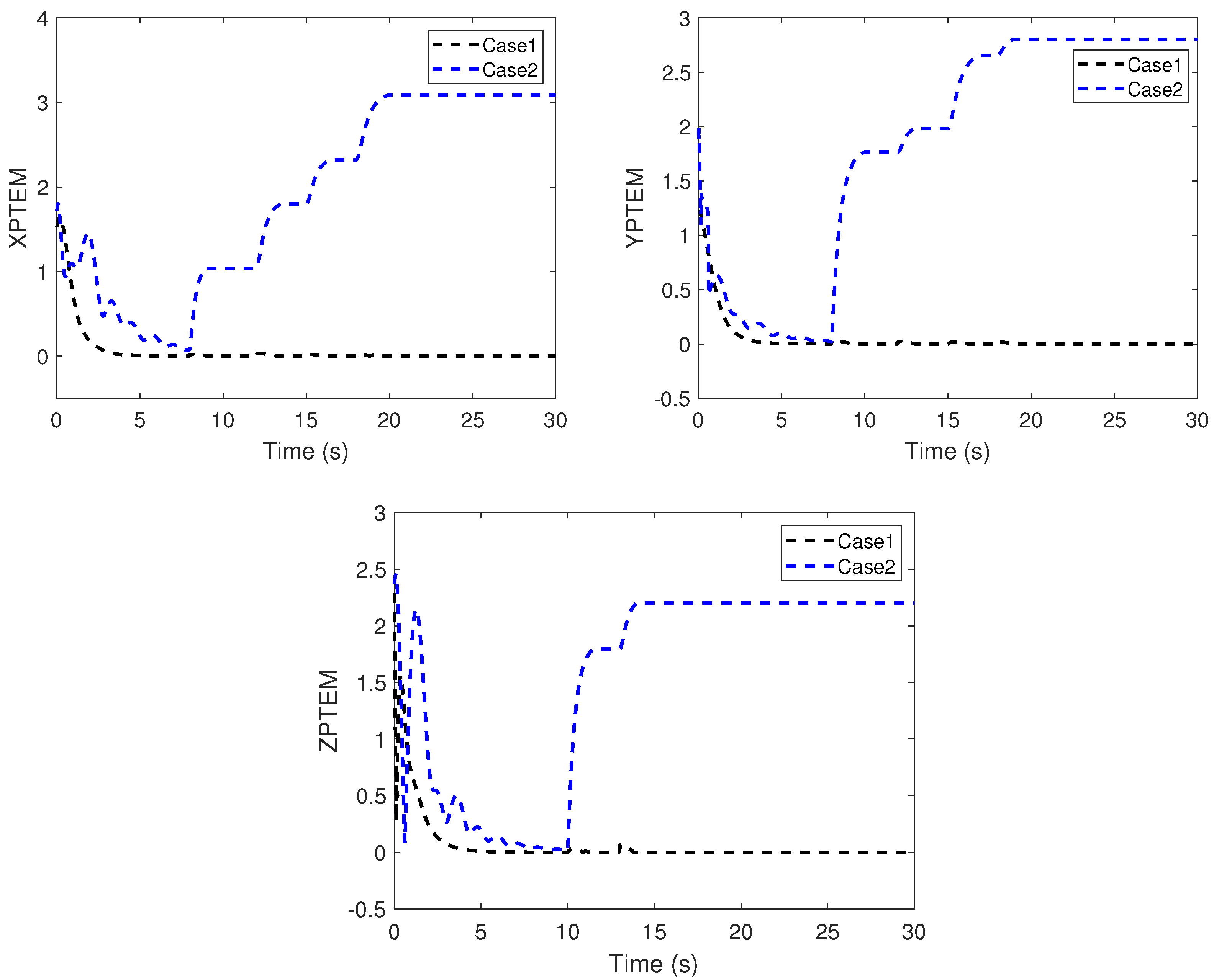
The performance of the proposed adaptive fault-tolerant time-varying formation tracking scheme is compared with the robust backstepping sliding-mode control scheme in [41]. To quantitatively evaluate the fault-tolerant time-varying formation tracking performance, X-axis position tracking error metric (XPTEM), Y-axis position tracking error metric (YPTEM), and Z-axis position tracking error metric (ZPTEM) are defined as
XPTEM = i = 1 4 | z ˜ i x | 2 , YPTEM = i = 1 4 | z ˜ i y | 2 , ZPTEM = i = 1 2 | e ˜ i z p | 2 .
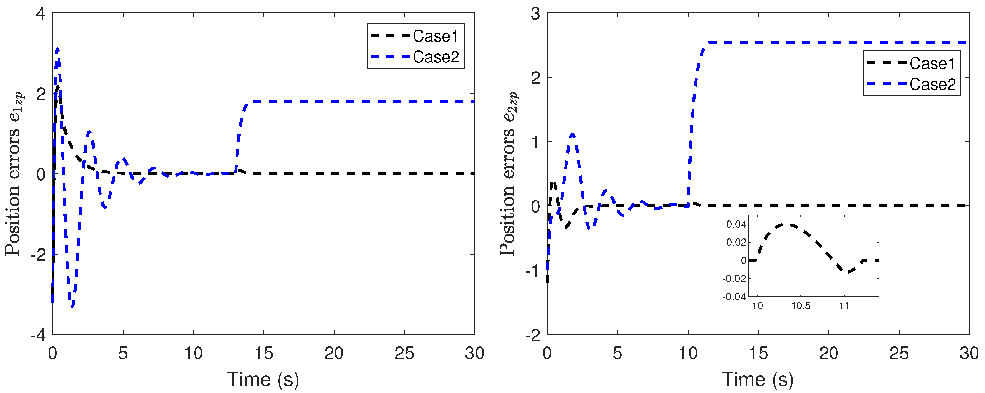
The position snapshots of the HMASs in the X Y plane at different time instants is shown in Figure 5. The time-varying formation errors of all agents in the X Y plane are depicted in Figure 6. The altitude tracking error of UAVs is shown in Figure 7.
From these curves, it can be seen that the tracking performance by the proposed control scheme is better than the robust backstepping sliding-mode control scheme in [41]. Furthermore, under the proposed control scheme, all tracking errors of the systems are uniformly ultimately bounded. From Figure 6 and Figure 7, it can be seen that the tracking errors under the scheme in [41] have sharp deviations from the small region containing zero when the actuator fault occurs. The position tracking error metrics are shown in Figure 8. It can be seen from these curves that the proposed control scheme has better performance than the scheme in [41]. From Figure 5, Figure 6, Figure 7 and Figure 8, we can know that the expected time-varying formation is achieved for the HMASs in the presence of actuator faults, parameter uncertainties and external disturbances. The effectiveness of the proposed fault-tolerant formation control scheme is verified by the simulation study.

6. Conclusions

In this paper, an adaptive fault-tolerant time-varying formation control scheme is designed for a heterogeneous multi-agent system composed of multiple UAVs and USVs with actuator faults, parameter uncertainties and external disturbances under directed communication topology. Based on the unified dynamic model of UAVs and USVs in the X Y plane, a distributed fault-tolerant formation controller utilizing adaptive control and RBFNN is proposed. At the same time, a decentralized formation tracking controller is designed for the altitude control system of UAVs. Based on Lyapunov stability theory, the time-varying formation errors and tracking errors are uniformly ultimated bounded, and the pre-defined time-varying formation for multiple UAVs and USVs can be realized. Simulation results verify the effectiveness of the proposed scheme. Nevertheless, the communication topology is fixed in this study. Hence, a fault-tolerant formation control for multiple UAVs and USVs under switch topology will be investigated in our future works.

Author Contributions

Conceptualization, S.L.; methodology, S.L.; software, S.L.; validation, S.L.; writing—original draft preparation, S.L.; writing—review and editing, S.L., B.J., Z.M. and Y.M.; supervision, Z.M. and Y.M.; project administration, B.J.; funding acquisition, S.L., B.J., Z.M. and Y.M. All authors have read and agreed to the published version of the manuscript.

Funding

This research was funded by National Natural Science Foundation of China (No. 62020106003, 61922042), 111 Project (No. B20007), Qing Lan Project, Fundamental Research Funds for Central Universities (No. FRF-BD-20-10A), Research Fund of State Key Laboratory of Mechanics and Control of Mechanical Structures (Nanjing University of Aeronautics and Astronautics) (No. MCMS-I-0521G05), Postgraduate Research and Practice Innovation Program of Jiangsu Province (No. KYCX20_0206), China Scholarship Council (No. 202006830062).

Institutional Review Board Statement

Not applicable.

Informed Consent Statement

Not applicable.

Data Availability Statement

Not applicable.

Conflicts of Interest

The authors declare no conflict of interest.

References

  1. Yu, Z.; Zhang, Y.; Jiang, B.; Yu, X.; Fu, J.; Jin, Y.; Chai, T. Distributed adaptive fault-tolerant close formation flight control of multiple trailing fixed-wing UAVs. ISA Trans. 2020, 106, 181–199. [Google Scholar] [CrossRef] [PubMed]
  2. Liu, C.; Jiang, B.; Zhang, K.; Patton, R.J. Distributed Fault-Tolerant Consensus Tracking Control of Multi-Agent Systems under Fixed and Switching Topologies. IEEE Trans. Circuits Syst. I 2021, 68, 1646–1658. [Google Scholar] [CrossRef]
  3. Yazdani, S.; Haeri, M. Robust adaptive fault-tolerant control for leader-follower flocking of uncertain multi-agent systems with actuator failure. ISA Trans. 2017, 71, 227–234. [Google Scholar] [CrossRef]
  4. Oh, K.K.; Park, M.C.; Ahn, H.S. A survey of multi-agent formation control. Automatica 2015, 53, 424–440. [Google Scholar] [CrossRef]
  5. Li, T.; Qiu, Q.; Zhao, C. A Fully Distributed Protocol with an Event-Triggered Communication Strategy for Second-Order Multi-Agent Systems Consensus with Nonlinear Dynamics. Sensors 2021, 21, 4059. [Google Scholar] [CrossRef]
  6. Cao, Y.; Yu, W.; Ren, W.; Chen, G. An Overview of Recent Progress in the Study of Distributed Multi-Agent Coordination. IEEE Trans. Ind. Informat. 2013, 9, 427–438. [Google Scholar] [CrossRef]
  7. Ding, Z.; Li, Z. Distributed adaptive consensus control of nonlinear output-feedback systems on directed graphs. Automatica 2016, 72, 46–52. [Google Scholar] [CrossRef]
  8. Shi, Y.; Yin, Y.; Wang, S.; Liu, Y.; Liu, F. Distributed leader-following consensus of nonlinear multi-agent systems with nonlinear input dynamics. Neurocomputing 2018, 286, 193–197. [Google Scholar] [CrossRef]
  9. Qin, J.; Ma, Q.; Shi, Y.; Wang, L. Recent Advances in Consensus of Multi-Agent Systems: A Brief Survey. IEEE Trans. Ind. Electron. 2017, 64, 4972–4983. [Google Scholar] [CrossRef]
  10. Sakthivel, R.; Parivallal, A.; Kaviarasan, B.; Lee, H.; Lim, Y. Finite-time consensus of Markov jumping multi-agent systems with time-varying actuator faults and input saturation. ISA Trans. 2018, 83, 89–99. [Google Scholar] [CrossRef]
  11. Fu, J.; Wen, G.; Yu, W.; Ding, Z. Finite-Time Consensus for Second-Order Multi-Agent Systems with Input Saturation. IEEE Trans. Circuits Syst. II 2018, 65, 1758–1762. [Google Scholar] [CrossRef]
  12. Tan, C.; Cui, Y.; Li, Y. Global Consensus of High-Order Discrete-Time Multi-Agent Systems with Communication Delay and Saturation Constraint. Sensors 2022, 22, 1007. [Google Scholar] [CrossRef] [PubMed]
  13. Tian, X.; Liu, H.; Liu, H. Robust finite-time consensus control for multi-agent systems with disturbances and unknown velocities. ISA Trans. 2018, 80, 73–80. [Google Scholar] [CrossRef]
  14. He, L.; Sun, X.; Lin, Y. Distributed output-feedback formation tracking control for unmanned aerial vehicles. Int. J. Syst. Sci. 2016, 47, 3919–3928. [Google Scholar] [CrossRef]
  15. Wang, R.; Dong, X.; Li, Q.; Ren, Z. Distributed Time-Varying Output Formation Control for General Linear Multiagent Systems with Directed Topology. IEEE Trans. Control Netw. Syst. 2019, 6, 609–620. [Google Scholar] [CrossRef]
  16. Du, H.; Zhu, W.; Wen, G.; Duan, Z.; Lü, J. Distributed Formation Control of Multiple Quadrotor Aircraft Based on Nonsmooth Consensus Algorithms. IEEE Trans. Cybern. 2019, 49, 342–353. [Google Scholar] [CrossRef]
  17. Chen, F.; Dimarogonas, D.V. Leader-Follower Formation Control with Prescribed Performance Guarantees. IEEE Trans. Control Netw. Syst. 2021, 8, 450–461. [Google Scholar] [CrossRef]
  18. Zuo, S.; Song, Y.; Lewis, F.L.; Davoudi, A. Time-Varying Output Formation Containment of General Linear Homogeneous and Heterogeneous Multiagent Systems. IEEE Trans. Control Netw. Syst. 2019, 6, 537–548. [Google Scholar] [CrossRef]
  19. Hua, Y.; Dong, X.; Hu, G.; Li, Q.; Ren, Z. Distributed Time-Varying Output Formation Tracking for Heterogeneous Linear Multiagent Systems with a Nonautonomous Leader of Unknown Input. IEEE Trans. Autom. Control 2019, 64, 4292–4299. [Google Scholar] [CrossRef]
  20. Rahimi, R.; Abdollahi, F.; Naqshi, K. Time-varying formation control of a collaborative heterogeneous multi agent system. Rob. Auton. Syst. 2014, 62, 1799–1805. [Google Scholar] [CrossRef]
  21. Mehrabian, A.R.; Khorasani, K. Constrained distributed cooperative synchronization and reconfigurable control of heterogeneous networked Euler–Lagrange multi-agent systems. Inf. Sci. 2016, 370–371, 578–597. [Google Scholar] [CrossRef]
  22. Zhang, Y.; Jiang, J. Bibliographical review on reconfigurable fault-tolerant control systems. Annu. Rev. Control 2008, 32, 229–252. [Google Scholar] [CrossRef]
  23. Yang, H.; Han, Q.L.; Ge, X.; Ding, L.; Xu, Y.; Jiang, B.; Zhou, D. Fault-Tolerant Cooperative Control of Multiagent Systems: A Survey of Trends and Methodologies. IEEE Trans. Ind. Informat. 2020, 16, 4–17. [Google Scholar] [CrossRef]
  24. Yin, S.; Luo, H.; Ding, S.X. Real-Time Implementation of Fault-Tolerant Control Systems with Performance Optimization. IEEE Trans. Ind. Electron. 2014, 61, 2402–2411. [Google Scholar] [CrossRef]
  25. Zhu, J.; Yang, G.; Zhang, W.; Yu, L. Cooperative Fault Tolerant Tracking Control for Multiagent Systems: An Intermediate Estimator-Based Approach. IEEE Trans. Cybern. 2018, 48, 2972–2980. [Google Scholar] [CrossRef] [PubMed]
  26. Khalili, M.; Zhang, X.; Cao, Y.; Polycarpou, M.M.; Parisini, T. Distributed adaptive fault-tolerant leader-following formation control of nonlinear uncertain second-order multi-agent systems. Int. J. Robust Nonlinear Control 2018, 28, 4287–4308. [Google Scholar] [CrossRef]
  27. Hua, Y.; Dong, X.; Li, Q.; Ren, Z. Distributed Fault-Tolerant Time-Varying Formation Control for Second-Order Multi-Agent Systems with Actuator Failures and Directed Topologies. IEEE Trans. Circuits Syst. II 2018, 65, 774–778. [Google Scholar] [CrossRef]
  28. Ma, H.; Yang, G. Adaptive Fault Tolerant Control of Cooperative Heterogeneous Systems with Actuator Faults and Unreliable Interconnections. IEEE Trans. Autom. Control 2016, 61, 3240–3255. [Google Scholar] [CrossRef]
  29. Yadegar, M.; Meskin, N. Fault-tolerant control of nonlinear heterogeneous multi-agent systems. Automatica 2021, 127, 109514. [Google Scholar] [CrossRef]
  30. Jiang, W.; Wang, C.; Meng, Y. Fully distributed time-varying formation tracking control of linear multi-agent systems with input delay and disturbances. Syst. Control Lett. 2020, 146, 104814. [Google Scholar] [CrossRef]
  31. Dong, C.; Zhang, W.; Wang, Q.; Liu, Y. Time-varying anti-disturbance formation control for high-order non-linear multi-agent systems with switching directed topologies. IET Control Theory Appl. 2020, 14, 271–282. [Google Scholar] [CrossRef]
  32. Lin, H.; Wei, Q.; Liu, D.; Ma, H. Adaptive tracking control of leader-following linear multi-agent systems with external disturbances. Int. J. Syst. Sci. 2016, 47, 3167–3179. [Google Scholar] [CrossRef]
  33. Dong, Y.; Su, Y.; Liu, Y.; Xu, S. An internal model approach for multi-agent rendezvous and connectivity preservation with nonlinear dynamics. Automatica 2018, 89, 300–307. [Google Scholar] [CrossRef]
  34. Zhu, G.; Ma, Y.; Li, Z.; Malekian, R.; Sotelo, M. Event-Triggered Adaptive Neural Fault-Tolerant Control of Underactuated MSVs with Input Saturation. IEEE Trans. Intell. Transp. Syst. 2022, 23, 7045–7057. [Google Scholar] [CrossRef]
  35. Park, B.S.; Kwon, J.W.; Kim, H. Neural network-based output feedback control for reference tracking of underactuated surface vessels. Automatica 2017, 77, 353–359. [Google Scholar] [CrossRef]
  36. Kou, B.; Liu, Z.Q.; Xu, L.X. Fault-tolerant Control for Trajectory Tracking of Underactuated Unmanned Surface Vehicles with Actuator Faults. In Proceedings of the 2021 IEEE International Conference on Recent Advances in Systems Science and Engineering (RASSE), Shanghai, China, 12–14 December 2021; pp. 1–6. [Google Scholar]
  37. Gonzalez-Garcia, A.; Miranda-Moya, A.; Castañeda, H. Robust Visual Tracking Control Based on Adaptive Sliding Mode Strategy: Quadrotor UAV—Catamaran USV Heterogeneous System. In Proceedings of the 2021 International Conference on Unmanned Aircraft Systems (ICUAS), Athens, Greece, 15–18 June 2021; pp. 666–672. [Google Scholar]
  38. Zhou, S.Q.; Hua, H.C.; Dong, X.W.; Li, Q.D.; Ren, Z. Air-ground time varying formation tracking control for heterogeneous UAV-UGV swarm system. Aero Weapon. 2019, 26, 54–59. [Google Scholar]
  39. Mei, J.; Ren, W.; Chen, J. Distributed Consensus of Second-Order Multi-Agent Systems with Heterogeneous Unknown Inertias and Control Gains under a Directed Graph. IEEE Trans. Autom. Control 2016, 61, 2019–2034. [Google Scholar] [CrossRef]
  40. Ren, W.; Beard, R. Consensus seeking in multiagent systems under dynamically changing interaction topologies. IEEE Trans. Autom. Control 2005, 50, 655–661. [Google Scholar] [CrossRef]
  41. Chen, F.; Jiang, R.; Zhang, K.; Jiang, B.; Tao, G. Robust Backstepping Sliding-Mode Control and Observer-Based Fault Estimation for a Quadrotor UAV. IEEE Trans. Ind. Electron. 2016, 63, 5044–5056. [Google Scholar] [CrossRef]
  42. Song, Y.; He, L.; Zhang, D.; Qian, J.; Fu, J. Neuroadaptive Fault-Tolerant Control of Quadrotor UAVs: A More Affordable Solution. IEEE Trans. Neural Netw. Learn. Syst. 2019, 30, 1975–1983. [Google Scholar] [CrossRef]
  43. Chen, S.; Ho, D.W.C.; Li, L.; Liu, M. Fault-Tolerant Consensus of Multi-Agent System with Distributed Adaptive Protocol. IEEE Trans. Cybern. 2015, 45, 2142–2155. [Google Scholar] [CrossRef] [PubMed]
  44. Chen, G.; Song, Y.D. Robust fault-tolerant cooperative control of multi-agent systems: A constructive design method. J. Frankl. Inst. 2015, 352, 4045–4066. [Google Scholar] [CrossRef]
  45. Li, J.H.; Lee, P.M.; Jun, B.H.; Lim, Y.K. Point-to-point navigation of underactuated ships. Automatica 2008, 44, 3201–3205. [Google Scholar] [CrossRef]
Figure 1. The structure of the quadrotor UAV.
Sensors 22 06212 g001
Figure 2. The motion model of USV.
Sensors 22 06212 g002
Figure 3. Schematic of the control system.
Sensors 22 06212 g003
Figure 4. Directed communication topology.
Sensors 22 06212 g004
Figure 5. Position snapshots of the heterogeneous multi-agent system at different time instants. (a) t = 0 s. (b) t = 10 s. (c) t = 20 s. (d) t = 25 s.
Sensors 22 06212 g005
Figure 6. Position errors of time-varying formation in the X Y plane (Case 1: proposed scheme; Case 2: scheme in [41]).
Sensors 22 06212 g006
Figure 7. Altitude tracking error of UAVs (Case 1: proposed scheme; Case 2: scheme in [41]).
Sensors 22 06212 g007
Figure 8. XPTEM, YPTEM, and ZPTEM.
Sensors 22 06212 g008
Table 1. System parameters of UAVs and USVs.
ParameterValueUnitParameterValueUnit
m a i 2kg d μ s i 0.725 kg · s 1
g9.8 m · s 2 d ν s i 0.89 kg · s 1
J a x , J a y , J a z 1.5 N · s 2 · rad 1 d r s i −1.9 kg · m 2 · s 1
d i x , d i y , d i z 0.012 N · s · rad 1 d μ s i 1 −1.33 kg · s 1
m μ s i 25.8kg d ν s i 1 −36.47 kg · s 1
m ν s i 33.8kg d r s i 1 −0.75 kg · m 2 · s 1
m r s i 2.76kg
Publisher’s Note: MDPI stays neutral with regard to jurisdictional claims in published maps and institutional affiliations.