


A Plug-and-Play Solution for Smart Transducers in Industrial Applications Based on IEEE 1451 and IEC 61499 Standards


Abstract
:1. Introduction
Research Questions
- RQ1: How can the IEEE 1451 and IEC 61499 standards be integrated to embed smart transducers in industrial applications?
- RQ2: What plug-and-play level can be achieved in the industrial context?
- RQ3: What advantages can be drawn from the automatic integration of smart transducers compliant with IEEE 1451?
2. Background and Related Work
2.1. IEEE 1451—Smart Transducers
2.2. IEC 61499—Distributed Industrial Systems
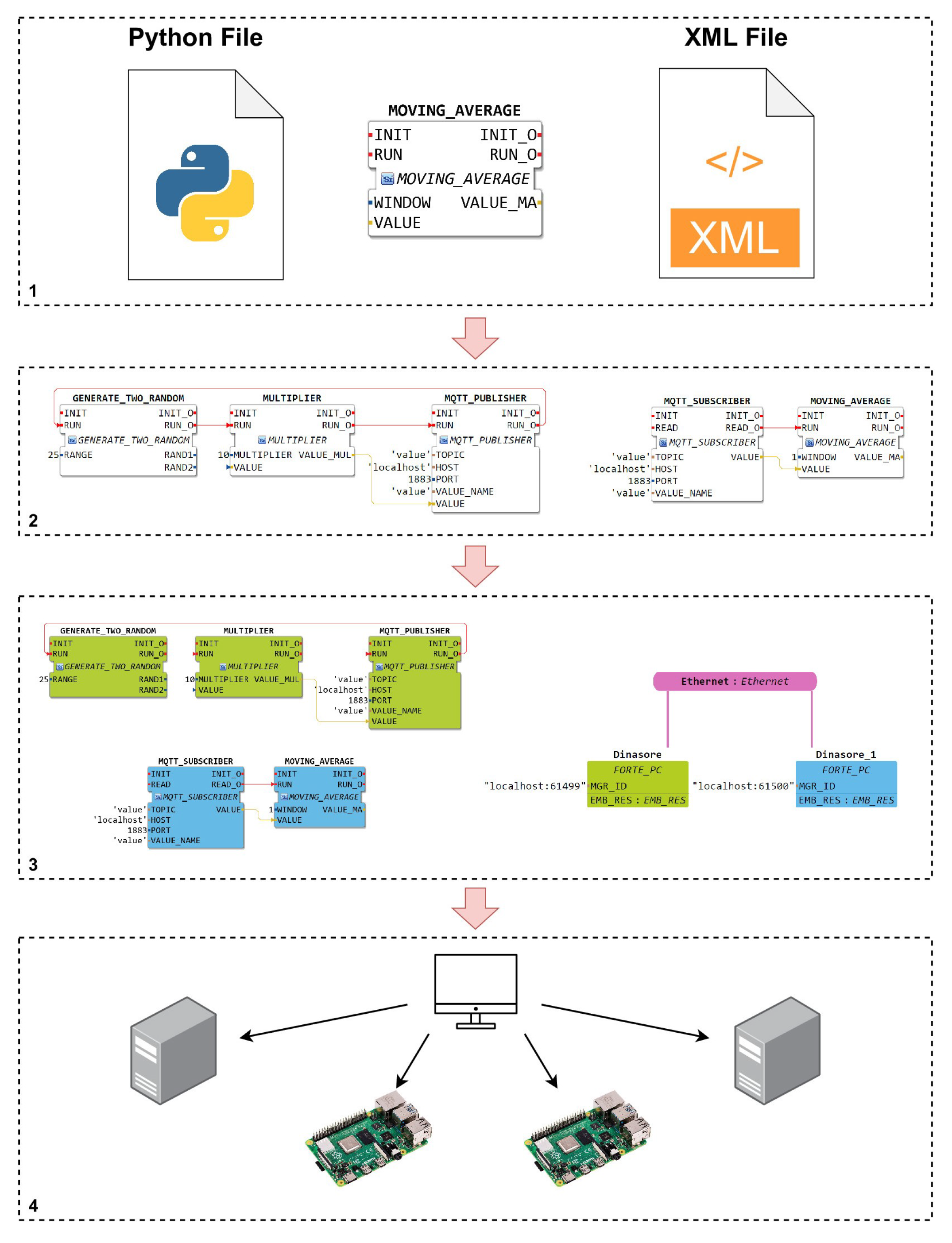
4diac IDE and DINASORE Framework
- Build new function blocks, writing the executable code in a Python file, and defining its interfaces in an XML file;
- Draw the application (function block network), dragging and dropping function blocks and interconnecting them in the 4diac IDE editor;
- Map each function block to the device (running DINASORE) that should execute it;
- Deploy the solution to the respective devices.
2.3. IEEE 1451 and IEC 61499 Interoperability
2.4. Plug and Play
3. Architecture
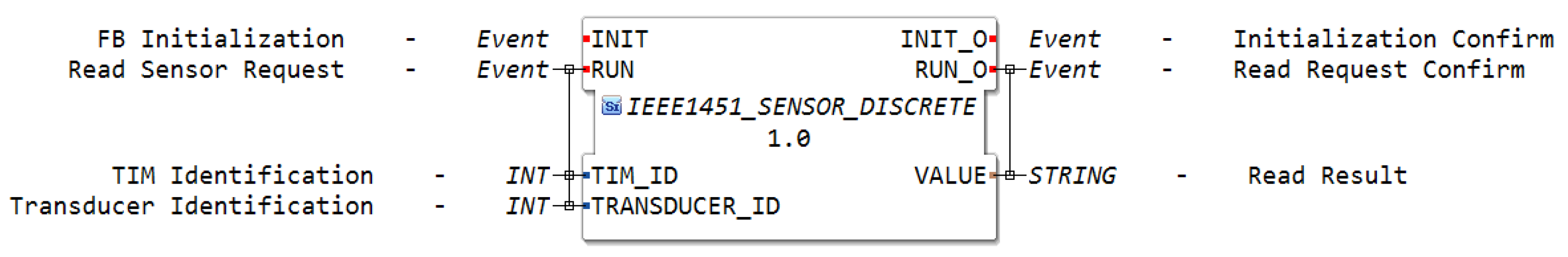
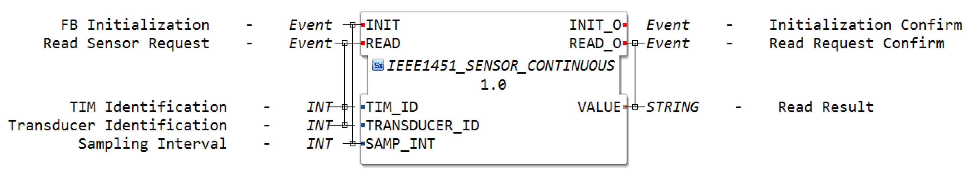
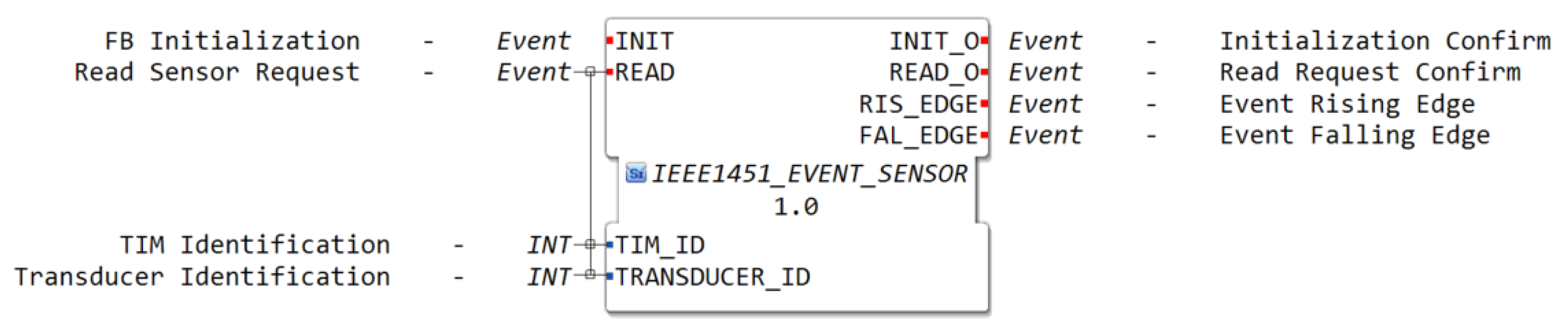
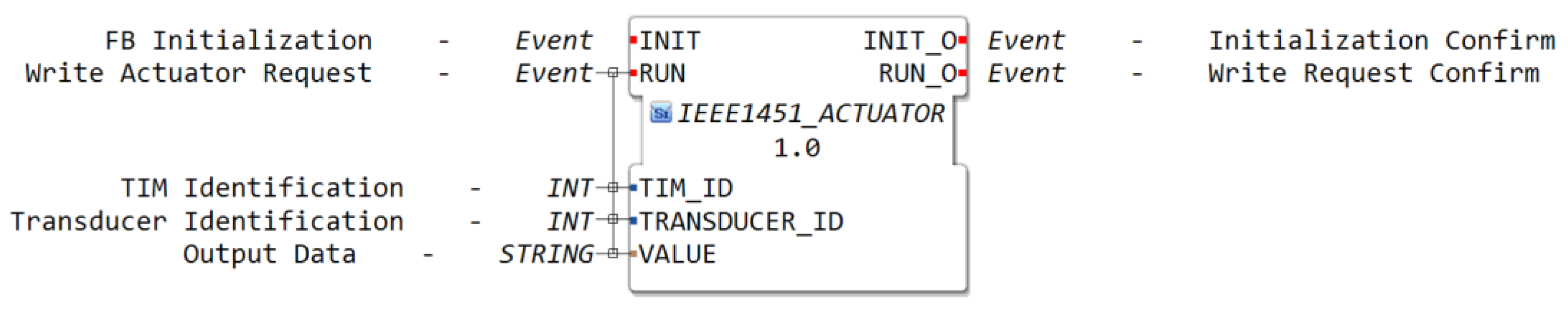
3.1. Smart Function Block Definition
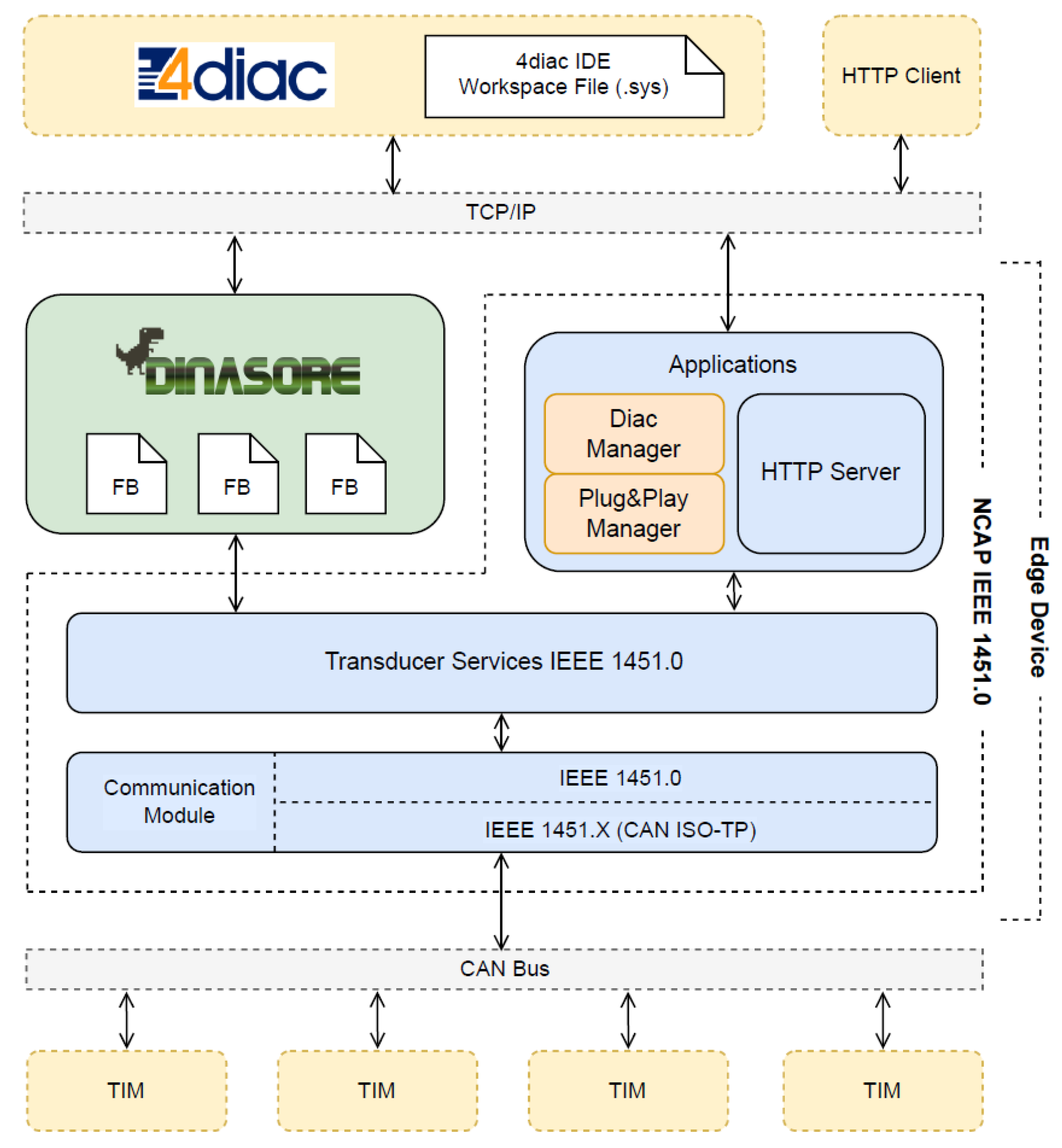
3.2. Edge Device Architecture
4. Validation Scenario, Performance Tests, and Results
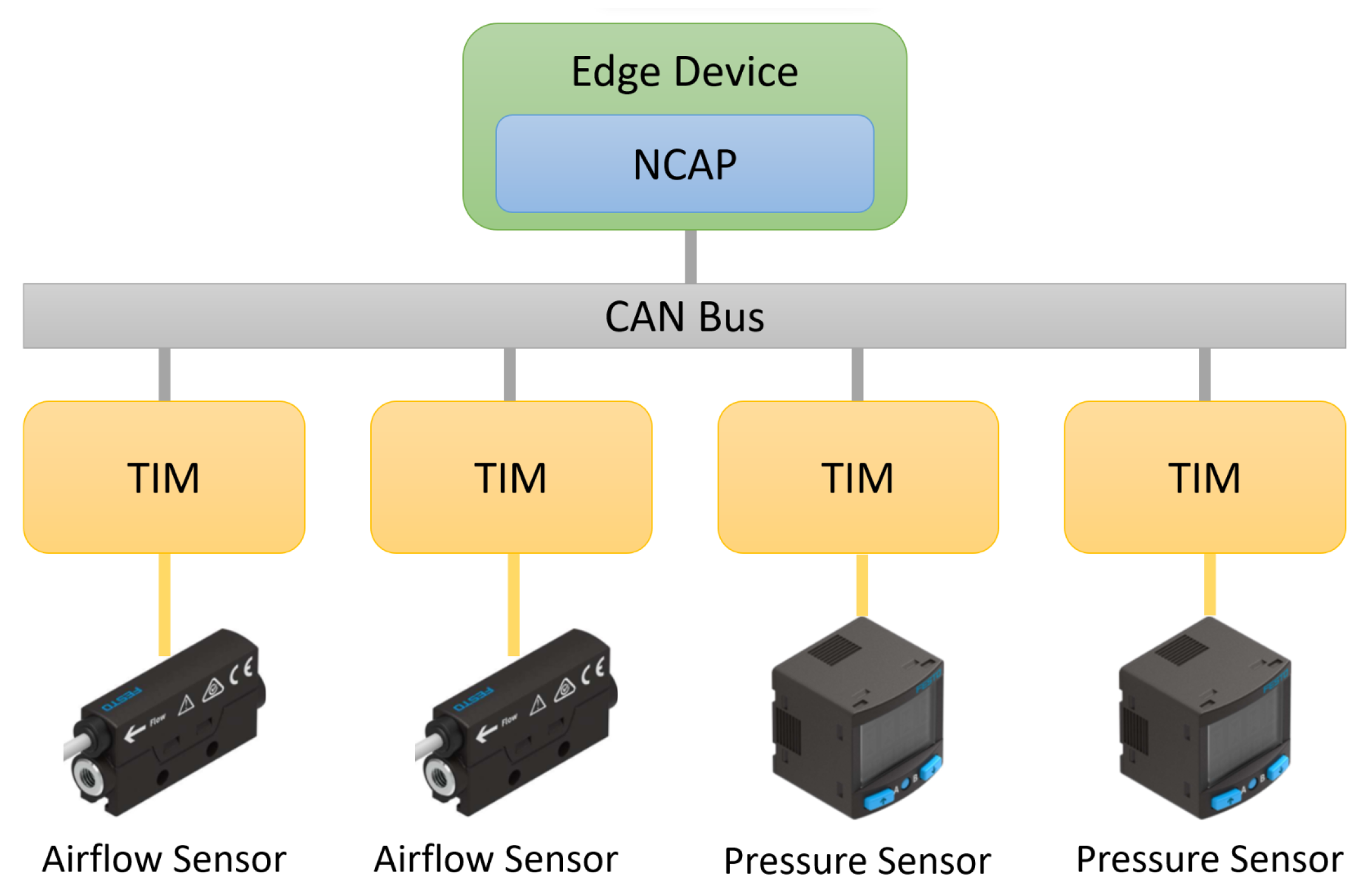
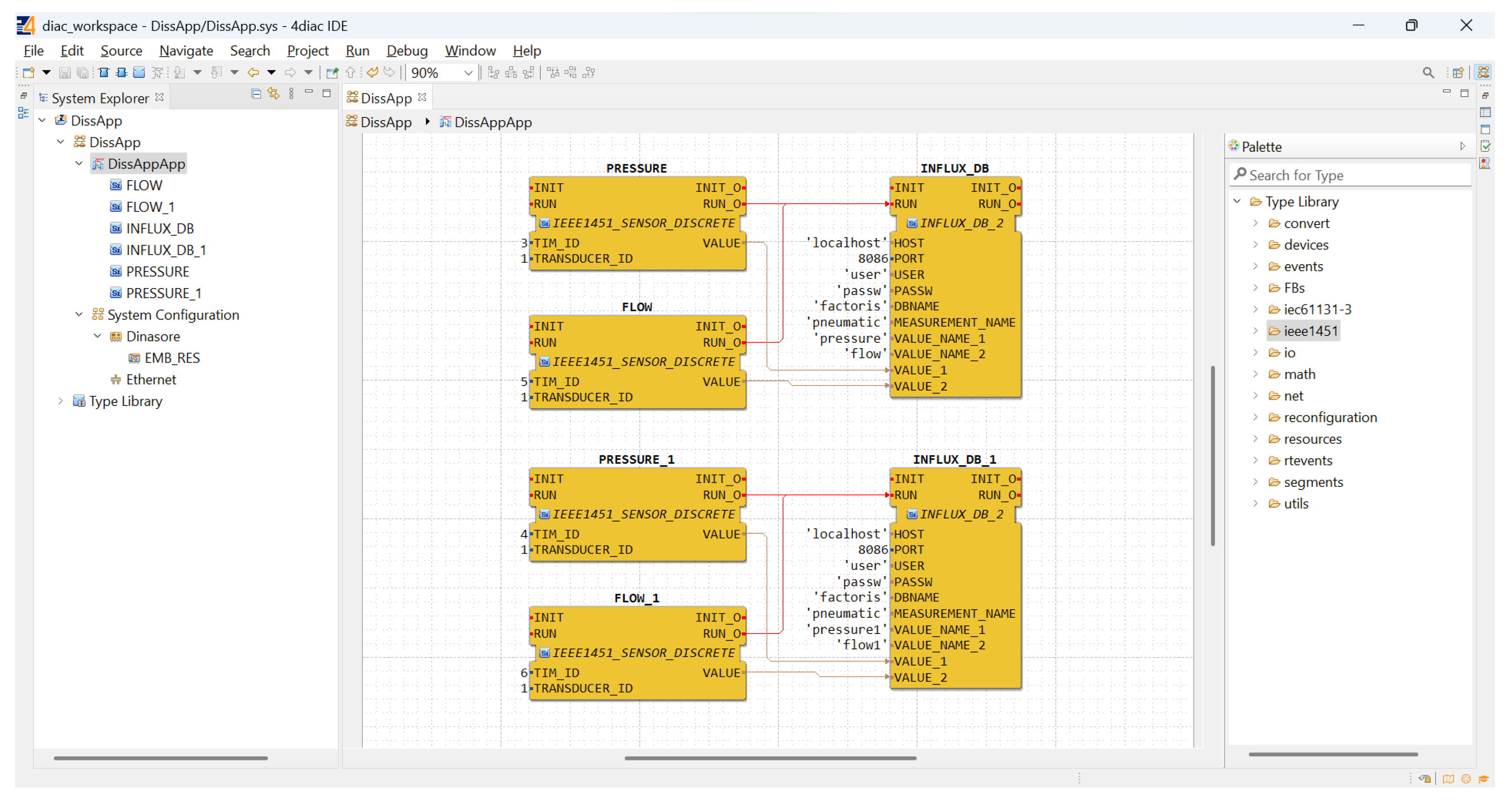
4.1. FactoRIS Validation Scenario
- Two flow sensors and two pressure sensors needed to be connected to the application. Thus, each one of the sensors was connected to a different TIM, which resulted in the connection of four TIMs in the same CAN bus.
4.2. Performance Tests
4.2.1. Registration Time Tests
- The TIM sends a Register command to the NCAP. The NCAP registers the TIM and responds with the new destId (CAN address).
- The NCAP sends a Read TEDS command to get MetaTEDS;
- If the MaxChan (number of implemented TransducerChannels) field of MetaTEDS is greater than zero, the NCAP sends Read TEDS commands to get the TransducerChannelTEDS of each transducer channel from that TIM. The NCAP registers each transducer channel with the associated TEDS;
- The NCAP interprets the TransducerChannelTEDS of each transducer channel to get the physical units;
- The NCAP adds the corresponding function block to the 4diac IDE workspace file.
4.2.2. Discovery Time Tests
- The NCAP sends a Discover command in broadcast to the network;
- Each TIM that is already registered responds to the Discover command with its destId;
- The NCAP registers internally a new TIM with the given destId;
- The NCAP sends a Read TEDS command to get MetaTEDS for each TIM;
- If the MaxChan (number of implemented TransducerChannels) field of MetaTEDS is greater than zero, the NCAP sends Read TEDS commands to get the TransducerChannelTEDS of each transducer channel from that TIM. The NCAP registers each transducer channel with the associated TEDS;
- The NCAP interprets the TransducerChannelTEDS of each transducer channel to get the physical units;
- The NCAP adds the corresponding function block to the 4diac IDE workspace file.
4.2.3. Read Sensor Time Tests
4.2.4. Tests Summary
5. Conclusions
6. Future Work
Author Contributions
Funding
Institutional Review Board Statement
Informed Consent Statement
Data Availability Statement
Acknowledgments
Conflicts of Interest
References
- VDI/VDE-Gesellschaft Mess- und Automatisierungstechnik. Cyber-Physical Systems: Chancen und Nutzen aus Sicht der Automation. In Thesen und Handlungsfelder; 2013; Available online: https://www.vdi.de/ueber-uns/presse/publikationen/details/cyber-physical-systems-chancen-und-nutzen-aus-sicht-der-automation (accessed on 7 October 2022).
- Monostori, L. Cyber-physical production systems: Roots, expectations and R&D challenges. Procedia CIRP 2014, 17, 9–13. [Google Scholar]
- Song, E.Y.; Lee, K. Understanding IEEE 1451-Networked smart transducer interface standard—What is a smart transducer? IEEE Instrum. Meas. Mag. 2008, 11, 11–17. [Google Scholar] [CrossRef]
- IEEE 1451.0-2007; IEEE Standard for a Smart Transducer Interface for Sensors and Actuators—Common Functions, Communication Protocols, and Transducer Electronic Data Sheet (TEDS) Formats. IEEE: Piscataway Township, NJ, USA, 2007; pp. 1–335.
- IEEE 1451.1-1999; IEEE Standard for a Smart Transducer Interface for Sensors and Actuators—Network Capable Application Processor Information Model. IEEE: Piscataway Township, NJ, USA, 2000.
- IEEE 1451.2-1997; IEEE Standard for a Smart Transducer Interface for Sensors and Actuators—Transducer to Microprocessor Communication Protocols and Transducer Electronic Data Sheet (TEDS) Formats. IEEE: Piscataway Township, NJ, USA, 1998.
- IEEE 1451.3-2003; IEEE Standard for a Smart Transducer Interface for Sensors and Actuators: Digital Communication and Transducer Electronic Data (TEDS) Formats for Distributed Multidrop Systems. IEEE: Piscataway Township, NJ, USA, 2004.
- IEEE 1451.4-2004; IEEE Standard for a Smart Transducer Interface for Sensors and Actuators—Mixed-Mode Communication Protocols and Transducer Electronic Data Sheet (TEDS) Formats. IEEE: Piscataway Township, NJ, USA, 2004.
- IEEE 1451.5-2007; IEEE Standard for a Smart Transducer Interface for Sensors and Actuators: Wireless Communication Protocols and Transducer Electronic Data Sheet (TEDS) Formats. IEEE: Piscataway Township, NJ, USA, 2007.
- Kher, S.; Jinran, C.; Somani, A.K. IEEE 1451 standard and wireless sensor networks: An over view of fault tolerant algorithms. In Proceedings of the 2006 IEEE International Conference on Electro Information Technology, East Lansing, MI, USA, 7–10 May 2006; pp. 227–232. [Google Scholar] [CrossRef]
- IEEE 1451.7-2010; IEEE Standard for Smart Transducer Interface for Sensors and Actuators–Transducers to Radio Frequency Identification (RFID) Systems Communication Protocols and Transducer Electronic Data Sheet Formats. IEEE: Piscataway Township, NJ, USA, 2010.
- Pinto, R.; Espírito-Santo, A.; Paciello, V. Proposal of a Sustainable e-Bike Sharing Infrastructure Based on the IEEE 1451 Standard. In Proceedings of the IECON Proceedings (Industrial Electronics Conference), Lisbon, Portugal, 14–17 October 2019; pp. 5538–5543. [Google Scholar] [CrossRef]
- Abrishambaf, R.; Rocha, H.D.; Espirito-Santo, A. IEC 61499 and IEEE 1451 for Distributed Control and Measurement Systems. In Proceedings of the IECON Proceedings (Industrial Electronics Conference), Toronto, ON, Canada, 13–16 October 2021. [Google Scholar]
- IEC 61499-1:2012; Function Blocks—Part 1: Architecture. IEC (International Electrotechnical Commission): Geneve, Switzerland, 2012.
- Vyatkin, V. IEC 61499 as enabler of distributed and intelligent automation: State-of-the-art review. IEEE Trans. Ind. Informatics 2011, 7, 768–781. [Google Scholar] [CrossRef]
- Vyatkin, V. The IEC 61499 standard and its semantics. IEEE Ind. Electron. Mag. 2009, 3, 40–48. [Google Scholar] [CrossRef]
- IEC 61499-1:2012; Function Blocks—Part 4: Rules for Compliance Profiles. IEC (International Electrotechnical Commission): Geneve, Switzerland, 2013.
- Pereira, E.; Reis, J.; Gonçalves, G. DINASORE: A Dynamic Intelligent Reconfiguration Tool for Cyber-Physical Production Systems; Eclipse Foundation: Ottawa, ON, Canada, 2020. [Google Scholar]
- Bernhard, H.P.; Zoitl, A.; Springer, A. Smart Transducers in Distributed and Model-Driven Control Applications: Empowering Seamless Internet of Things Integration. IEEE Ind. Electron. Mag. 2019, 13, 57–64. [Google Scholar] [CrossRef]
- da Rocha, H.; Abrishambaf, R.; Pereira, J.; Santo, A.E. Integrating the IEEE 1451 and IEC 61499 Standards with the Industrial Internet Reference Architecture. Sensors 2022, 22, 1495. [Google Scholar] [CrossRef] [PubMed]
- Gonçalves, G.; Reis, J.; Pinto, R.; Alves, M.; Correia, J. A step forward on intelligent factories: A Smart Sensor-oriented approach. In Proceedings of the 19th IEEE International Conference on Emerging Technologies and Factory Automation, ETFA 2014, Barcelona, Spain, 16–19 September 2014. [Google Scholar] [CrossRef]
- Gonçalves, G.; Wolny, P.; Meyer, T. Review of Standardization Opportunities in Smart Industrial Components. 2016. Available online: https://repositorio-aberto.up.pt/handle/10216/140439 (accessed on 31 July 2022).
- Monostori, L.; Kádár, B.; Bauernhansl, T.; Kondoh, S.; Kumara, S.; Reinhart, G.; Sauer, O.; Schuh, G.; Sihn, W.; Ueda, K. Cyber-physical systems in manufacturing. CIRP Ann. 2016, 65, 621–641. [Google Scholar] [CrossRef]
- Sauer, O.; Ebel, M. Plug-and-work von Produktionsanlagen und Übergeordneter Software. In Proceedings of the INFORMATIK 2007—Inform, Trifft Logistik, Bremen, Germany, 24–27 September 2007; Volume 2, pp. 331–338. [Google Scholar]
- Reinhart, G.; Krug, S.; Hüttner, S.; Mari, Z.; Riedelbauch, F.; Schlögel, M. Automatic configuration (Plug & Produce) of Industrial Ethernet networks. In Proceedings of the 2010 9th IEEE/IAS International Conference on Industry Applications, INDUSCON 2010, Sao Paulo, Brazil, 8–10 November 2010. [Google Scholar] [CrossRef]
- Dai, W.; Huang, W.; Vyatkin, V. Enabling plug-and-play software components in industrial cyber-physical systems by adopting service-oriented architecture paradigm. In Proceedings of the IECON Proceeding (Industrial Electron. Conference, Florence, Italy, 23–26 October 2016; pp. 5253–5258. [Google Scholar] [CrossRef]
- Juhás, M.; Gulan, M.; Neto, L.; Gonçalves, G.; Komenda, T.; Pickel, L.; Zhou, S.; Schickling, C.; Lokšík, M.; Morháč, M. FactoRIS—A Learning Factories Based Education Framework to Support Digital Transformation of Manufacturing SMEs. In Proceedings of the 12th Conference on Learning Factories (CLF 2022), Singapore, 11–13 April 2022. [Google Scholar]
- Neto, L.; Pinheiro, J.; Oliveira, D.; Gonçalves, G. Introducing students to zero defects, condition monitoring and system integration using a refurbished learning factory. In Proceedings of the 12th Conference on Learning Factories (CLF 2022), Singapore, 11–13 April 2022. [Google Scholar]


| # TIMs | Registration Time (, ms) |
|---|---|
| 1 | 714.315 |
| 2 | 858.835 |
| 3 | 1237.022 |
| 4 | 2190.061 |
| # TIMs | Discovery Time (, ms) |
|---|---|
| 1 | 852.134 |
| 2 | 1197.068 |
| 3 | 1777.288 |
| 4 | 2385.188 |
| # TIMs | Read Time (, ms) | Average (, ms) |
|---|---|---|
| 1 | 78.089 | 78.089 |
| 2 | 113.195 | 113.329 |
| 113.462 | ||
| 3 | 161.224 | 161.529 |
| 161.789 | ||
| 161.575 | ||
| 4 | 201.695 | 203.051 |
| 203.801 | ||
| 203.600 | ||
| 203.107 |
| # TIMs | Read Cycle Time (, ms) | Average (, ms) | Max Samples/s |
|---|---|---|---|
| 1 | 78.096 | 78.096 | 12.805 |
| 2 | 113.202 | 113.335 | 8.823 |
| 113.469 | |||
| 3 | 161.231 | 161.536 | 6.191 |
| 161.796 | |||
| 161.581 | |||
| 4 | 201.702 | 203.057 | 4.925 |
| 203.807 | |||
| 203.607 | |||
| 203.114 |
| # TIMs | Read Time (, ms) | Average (, ms) |
|---|---|---|
| 1 | 130.559 | 130.559 |
| 2 | 153.209 | 153.585 |
| 153.961 | ||
| 3 | 178.312 | 176.240 |
| 180.360 | ||
| 170.047 | ||
| 4 | 257.120 | 246.113 |
| 253.741 | ||
| 235.548 | ||
| 238.044 |
| # TIMs | Read Cycle Time (, ms) | Average (, ms) | Max Samples/s |
|---|---|---|---|
| 1 | 158.704 | 158.704 | 6.301 |
| 2 | 172.856 | 172.981 | 5.781 |
| 173.107 | |||
| 3 | 220.609 | 211.636 | 4.735 |
| 215.749 | |||
| 198.550 | |||
| 4 | 292.580 | 274.231 | 3.662 |
| 280.840 | |||
| 246.274 | |||
| 277.228 |
Publisher’s Note: MDPI stays neutral with regard to jurisdictional claims in published maps and institutional affiliations. |
© 2022 by the authors. Licensee MDPI, Basel, Switzerland. This article is an open access article distributed under the terms and conditions of the Creative Commons Attribution (CC BY) license (https://creativecommons.org/licenses/by/4.0/).
Share and Cite
Oliveira, D.; Pinheiro, J.; Neto, L.; Pinto, V.H.; Gonçalves, G. A Plug-and-Play Solution for Smart Transducers in Industrial Applications Based on IEEE 1451 and IEC 61499 Standards. Sensors 2022, 22, 7694. https://doi.org/10.3390/s22197694
Oliveira D, Pinheiro J, Neto L, Pinto VH, Gonçalves G. A Plug-and-Play Solution for Smart Transducers in Industrial Applications Based on IEEE 1451 and IEC 61499 Standards. Sensors. 2022; 22(19):7694. https://doi.org/10.3390/s22197694
Chicago/Turabian StyleOliveira, Diogo, João Pinheiro, Luís Neto, Vítor H. Pinto, and Gil Gonçalves. 2022. "A Plug-and-Play Solution for Smart Transducers in Industrial Applications Based on IEEE 1451 and IEC 61499 Standards" Sensors 22, no. 19: 7694. https://doi.org/10.3390/s22197694
APA StyleOliveira, D., Pinheiro, J., Neto, L., Pinto, V. H., & Gonçalves, G. (2022). A Plug-and-Play Solution for Smart Transducers in Industrial Applications Based on IEEE 1451 and IEC 61499 Standards. Sensors, 22(19), 7694. https://doi.org/10.3390/s22197694