
A High Gain Embedded Helix and Dielectric Rod Antenna with Low Side Lobe Levels for IoT Applications
 , and
, and
Abstract
:1. Introduction
2. Theoretical Analysis
2.1. The First Part
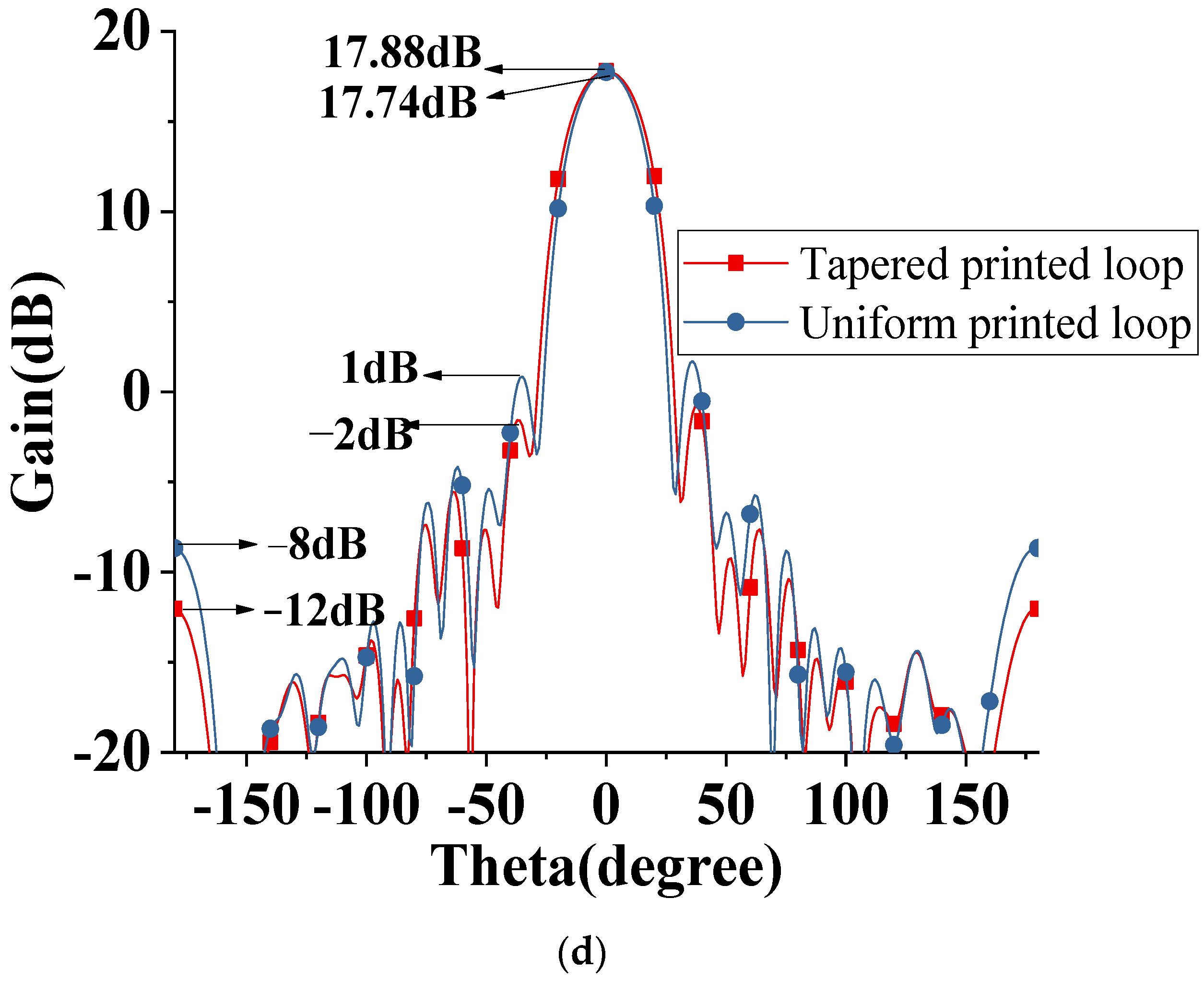
2.2. The Second Part
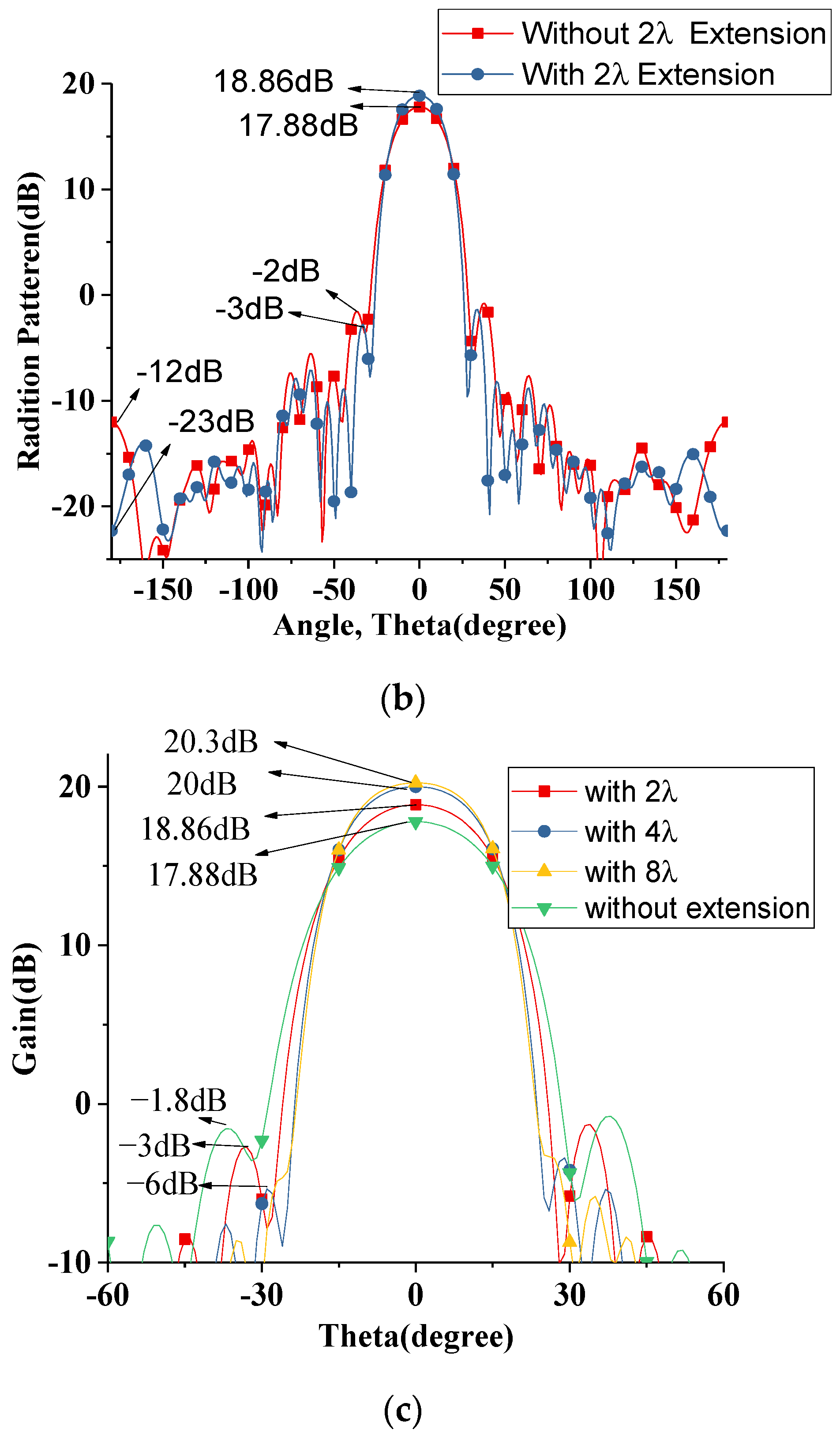
2.3. The Third Part
3. Design and Analysis of the Whole Structure
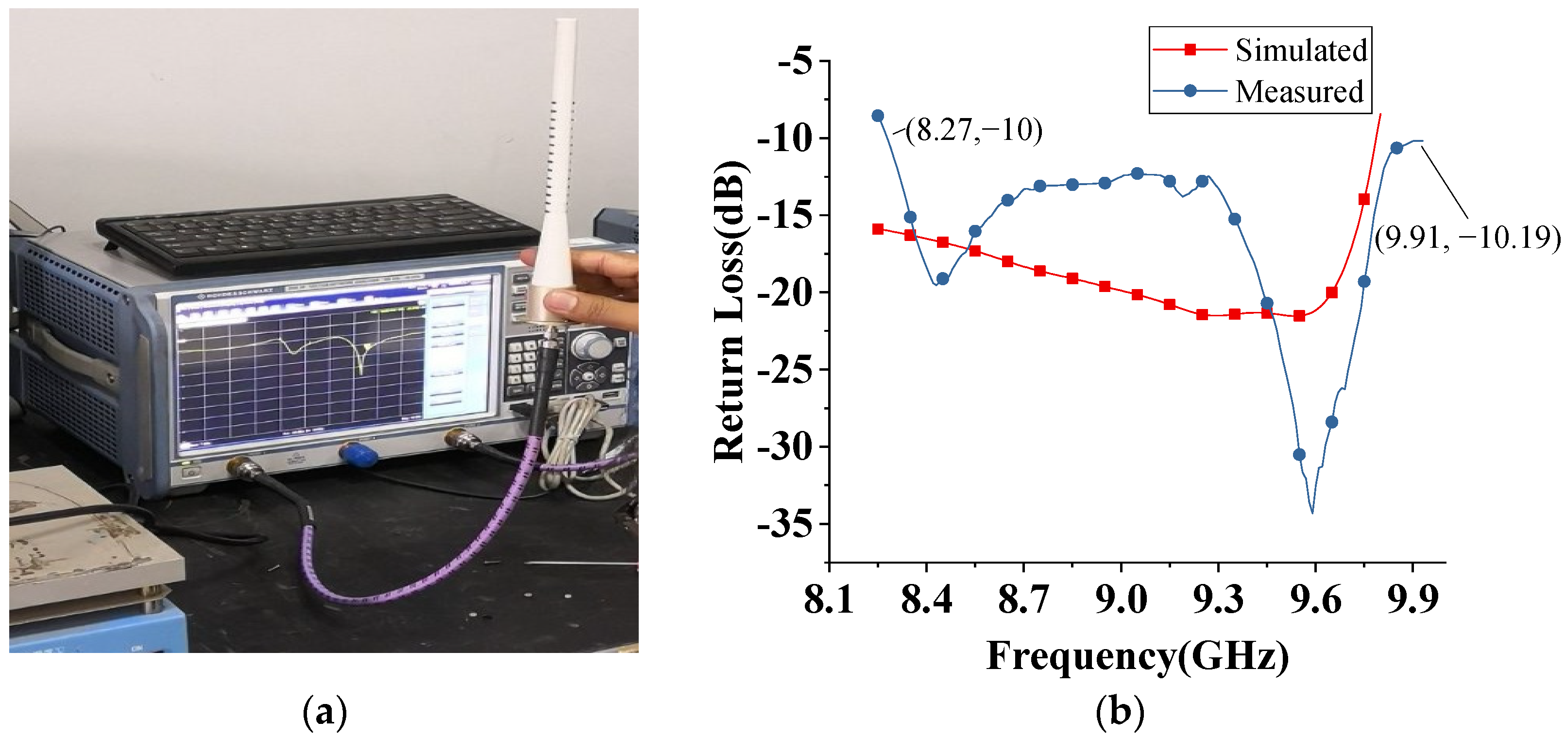
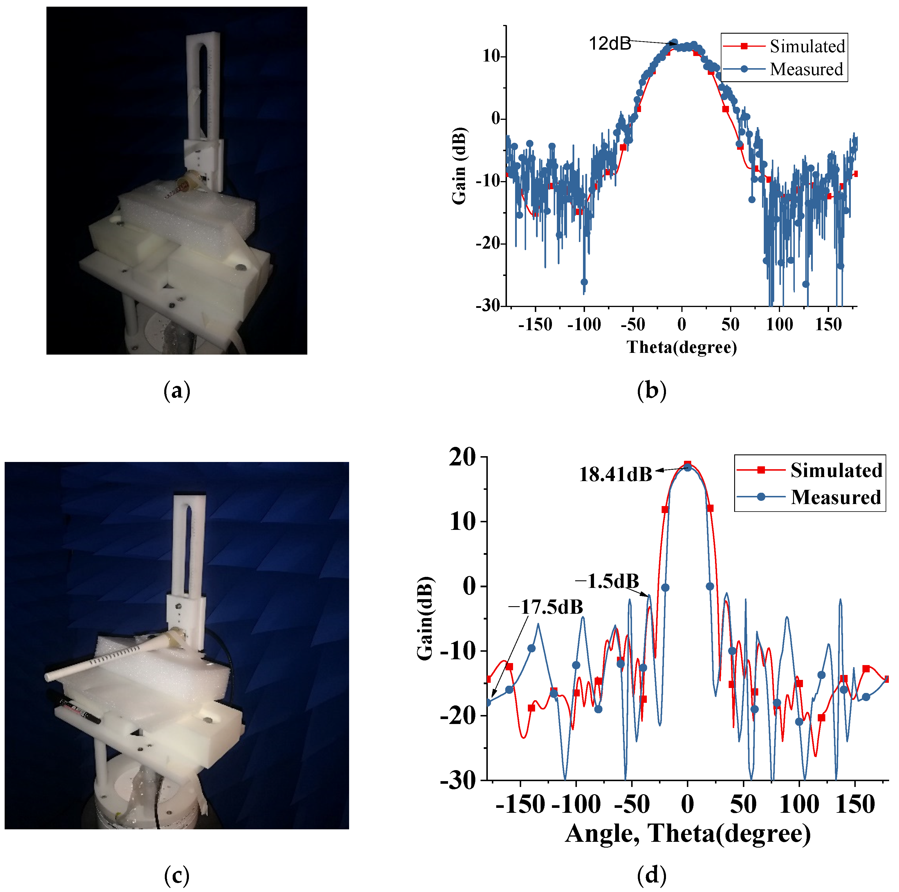
4. Fabrication and Measurement
5. Conclusions
Author Contributions
Funding
Institutional Review Board Statement
Informed Consent Statement
Data Availability Statement
Conflicts of Interest
References
- Ogbodo, E.U.; Abu-Mahfouz, A.M.; Kurien, A.M. A Survey on 5G and LPWAN-IoT for Improved Smart Cities and Remote Area Applications: From the Aspect of Architecture and Security. Sensors 2022, 22, 6313. [Google Scholar] [CrossRef]
- Sharif, A.; Ouyang, J.; Yang, F.; Chattha, H.T.; Imran, M.A.; Alomainy, A.; Abbasi, Q.H. Low-Cost Inkjet-Printed UHF RFID Tag-Based System for Internet of Things Applications Using Characteristic Modes. IEEE Internet Things J. 2019, 6, 3962–3975. [Google Scholar] [CrossRef] [Green Version]
- He, Y.; He, W.; Wong, H. A wideband circularly polarized cross-dipole antenna. IEEE Antennas Wireless Propag. Lett. 2014, 13, 67–70. [Google Scholar]
- Li, M.; Luk, K.M. Low-Cost Wideband Microstrip Antenna Array for 60-GHz Applications. IEEE Trans. Antennas Propag. 2014, 62, 3012–3018. [Google Scholar] [CrossRef]
- Samsuzzaman; Islam, M.T. Circularly Polarized Broadband Printed Antenna for Wireless Applications. Sensors 2018, 18, 4261. [Google Scholar] [CrossRef] [PubMed] [Green Version]
- Nguyen, H.Q.; Le, M.T. Multiband Ambient RF Energy Harvester with High Gain Wideband Circularly Polarized Antenna toward Self-Powered Wireless Sensors. Sensors 2021, 21, 7411. [Google Scholar] [CrossRef] [PubMed]
- Nematollahi, H.; Boutayeb, H.; Wu, K. Millimeter-wave circularly-polarized traveling-wave substrate integrated waveguide antennas. In Proceedings of the 2009 European Microwave Conference (EuMC), Rome, Italy, 29 September–1 October 2009; pp. 1555–1558. [Google Scholar]
- Yao, Y.; Cheng, X.; Yu, J.; Chen, X. Analysis and Design of a Novel Circularly Polarized Antipodal Linearly Tapered Slot Antenna. IEEE Trans. Antennas Propag. 2016, 64, 4178–4187. [Google Scholar] [CrossRef]
- Li, Y.; Luk, K.-M. A 60-GHz Wideband Circularly Polarized Aperture-Coupled Magneto-Electric Dipole Antenna Array. IEEE Trans. Antennas Propag. 2016, 64, 1325–1333. [Google Scholar] [CrossRef]
- Liu, C.; Guo, Y.; Bao, X.; Xiao, S.-Q. 60-GHz LTCC Integrated Circularly Polarized Helical Antenna Array. IEEE Trans. Antennas Propag. 2012, 60, 1329–1335. [Google Scholar] [CrossRef]
- Ji, Z.; Wang, K.X.; Wong, H. Circularly Polarized Dielectric Rod Waveguide Antenna for Millimeter-Wave Applications. IEEE Trans. Antennas Propag. 2018, 66, 5080–5087. [Google Scholar] [CrossRef]
- Toland, B.; Liu, C.C.; Ingerson, P.G. Design and Analysis of Arbitrarily Shaped Dielectric Antennas. Microw. J. 1997, 40, 278–283. [Google Scholar]
- Longsky, T.; Hazadra, P. Design of a Plexiglass Rod Antenna. In Proceedings of the 2017 Conference on Microwave Techniques (COMITE), Brno, Czech Republic, 20–21 April 2017. [Google Scholar]
- Kumar, C.; Srinivasan, V.V.; Lakshmeesha, V.K.; Pal, S. Design of Short Axial Length High Gain Dielectric Rod Antenna. IEEE Trans. Antennas Propag. 2010, 58, 4066–4069. [Google Scholar] [CrossRef]
- Liu, Y.; Chen, X. A Novel Microstrip-fed Dielectric ROD Antenna Array with High Gain. In Proceedings of the Progress in Electromagnetics Research Symposium Proceedings, Moscow, Russia, 19–23 August 2012. [Google Scholar]
- Chen, P.; Meng, R.; Zhu, Q. Design of Compact High-Gain Dielectric Rod Antennas and Arrays in Lossy Medium. Microw. Opt. Technol. Lett. 2013, 55, 2277–2282. [Google Scholar] [CrossRef]
- Ando, T.; Ohba, I.; Numata, S.; Yamauchi, J.; Nakano, H. Linearly and curvilinearly tapered cylindrical- dielectric-rod antennas. IEEE Trans. Antennas Propag. 2005, 53, 2827–2833. [Google Scholar] [CrossRef] [Green Version]
- Stroobandt, S.Y. An X-Band High-Gain Dielectric Rod Antenna. HEVERLEE 1997. Available online: http://citeseerx.ist.psu.edu/viewdoc/download?doi=10.1.1.205.7018&rep=rep1&type=pdf (accessed on 27 September 2022).
- Balanis, C.A. Antenna Theory: Analysis and Design; John Wiley & Sons: Hoboken, NJ, USA, 2016. [Google Scholar]
- King, E.H.; Wong, J.L.; Newman, E.H. Helical antennas. In Antenna Engineering Handbook; McGraw Hill: New York, NY, USA, 2007. [Google Scholar]
- Bahl, I.; Bhartia, P.; Stuchly, S. Design of microstrip antennas covered with a dielectric layer. IRE Trans. Antennas Propag. 1982, 30, 314–318. [Google Scholar] [CrossRef]
- Wang, H.; Fang, D.-G.; Zhang, B.; Che, W.-Q. Dielectric Loaded Substrate Integrated Waveguide (SIW) H-Plane Horn Antennas. IEEE Trans. Antennas Propag. 2010, 58, 640–647. [Google Scholar] [CrossRef]
- Elrashidi, A.; Elleithy, K.; Bajwa, H. Effect of Temperature on The Performance of a Cylindrical Microstrip Printed Antenna for Tm01 Mode Using Different Substrates. Int. J. Comput. Netw. Commun. 2011, 3, 1–19. [Google Scholar] [CrossRef]


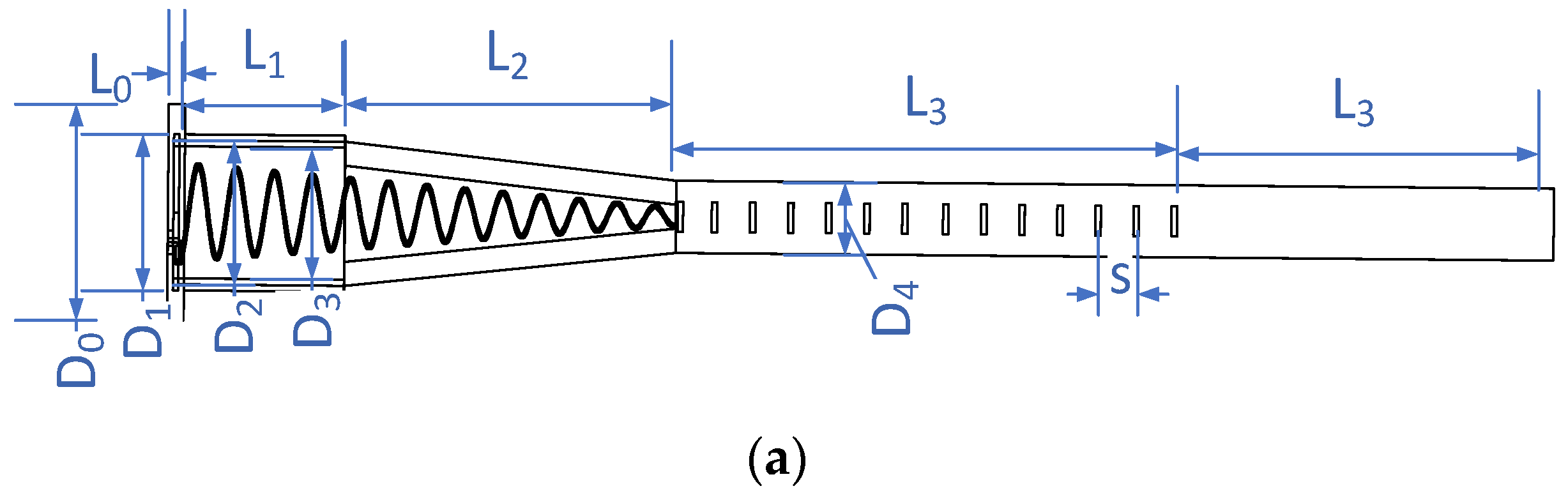
| Symbol | Value (mm) | Symbol | Value (mm) |
|---|---|---|---|
| L0 | 2 | D3 | 22 |
| L1 | 30 | D2 | 24 |
| L2 | 57.48 | D1 | 26 |
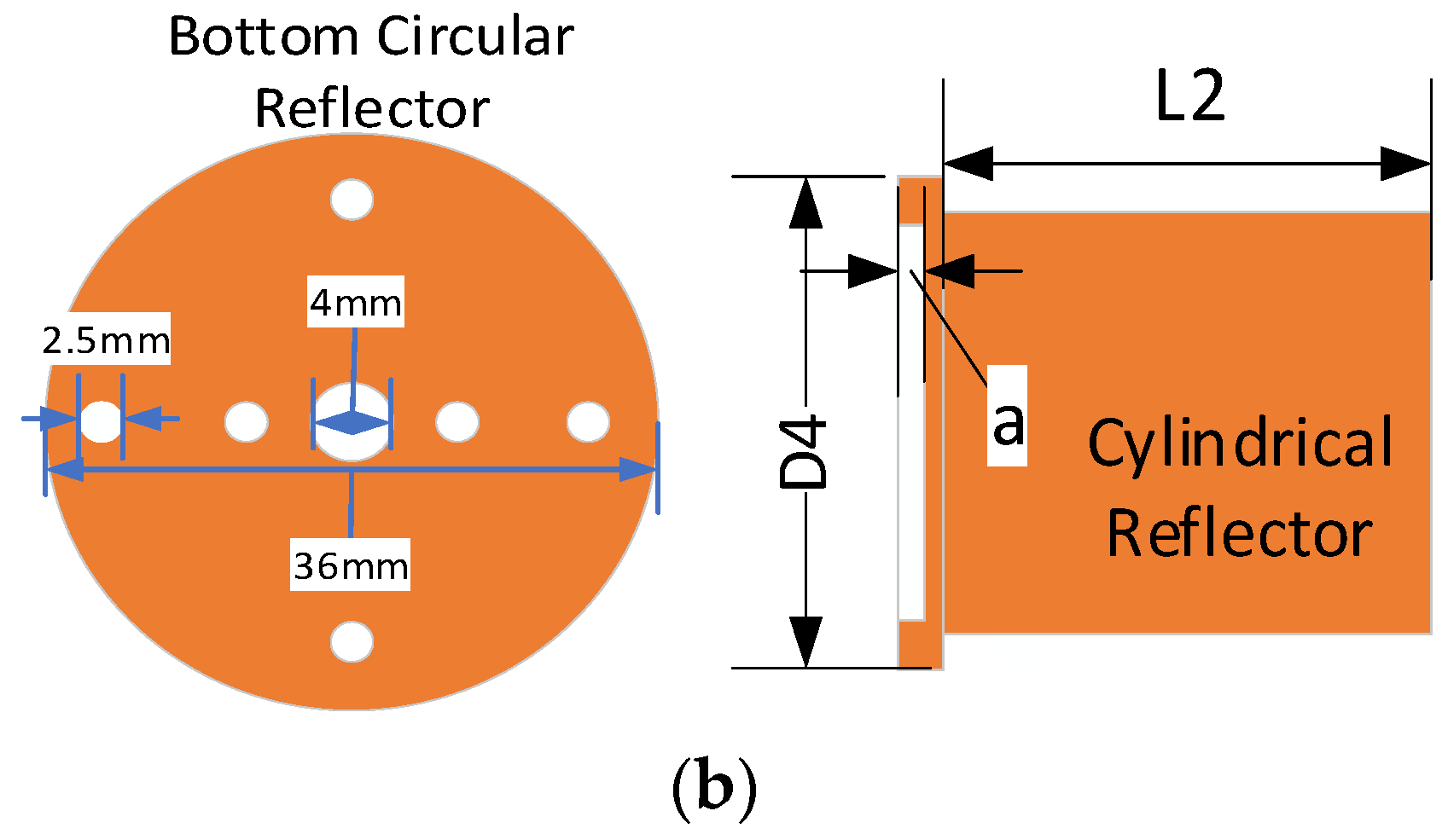
| L3 | 97.2 | D4 | 12 |
| L4 | 64 | S | 6.9 |
| a | 1 | D0 | 36 |
| SW | 2 | SL | 5 |
| SG | 6.9 |
Publisher’s Note: MDPI stays neutral with regard to jurisdictional claims in published maps and institutional affiliations. |
© 2022 by the authors. Licensee MDPI, Basel, Switzerland. This article is an open access article distributed under the terms and conditions of the Creative Commons Attribution (CC BY) license (https://creativecommons.org/licenses/by/4.0/).
Share and Cite
Nasir, M.; Xia, Y.; Sharif, A.B.; Guo, G.; Zhu, Q.; Ur Rehman, M.; Abbasi, Q.H. A High Gain Embedded Helix and Dielectric Rod Antenna with Low Side Lobe Levels for IoT Applications. Sensors 2022, 22, 7760. https://doi.org/10.3390/s22207760
Nasir M, Xia Y, Sharif AB, Guo G, Zhu Q, Ur Rehman M, Abbasi QH. A High Gain Embedded Helix and Dielectric Rod Antenna with Low Side Lobe Levels for IoT Applications. Sensors. 2022; 22(20):7760. https://doi.org/10.3390/s22207760
Chicago/Turabian StyleNasir, Muhammad, Yulong Xia, Abu Bakar Sharif, Guangjun Guo, Qi Zhu, Masood Ur Rehman, and Qammer Hussain Abbasi. 2022. "A High Gain Embedded Helix and Dielectric Rod Antenna with Low Side Lobe Levels for IoT Applications" Sensors 22, no. 20: 7760. https://doi.org/10.3390/s22207760