

Low-Complexity Lossless Coding of Asynchronous Event Sequences for Low-Power Chip Integration


Abstract
1. Introduction
- (1)
- A novel low-complexity lossless compression method for encoding raw event data represented as asynchronous event sequences, which is suitable for hardware implementation into ESP chips.
- (2)
- A novel low-complexity coding scheme for encoding residual errors by dividing the input range into several coding ranges arranged at concentric distances from an initial prediction.
- (3)
- A novel event sequence representation that removes the event timestamp information by dividing the input sequence into ordered same-timestamp event subsequences that can be encoded in separated bit streams.
- (4)
- A lossless event data codec that provides random access (RA) to any time window by using additional header information.
2. State-of-the-Art Methods
3. Proposed Low-Complexity Lossless Coding Framework
- spatial information i.e., the pixel positions where the event was triggered;
- polarity information where the symbol “” signals a decrease and symbol “1” signals an increase in the light intensity; and
- timestamp the time when the event was triggered.
3.1. Proposed Sequence Representation
3.2. Proposed Triple Threshold-Based Range Partition (TTP)
- (c1)
- is set by checking If true then otherwise,
- (c2)
- If then is set by checking If true, then and R1 is employed to represent on bits; otherwise
- (c3)
- If then is set by checking If true then and R2 is employed to represent on bits. Otherwise, and R3 is used to represent on bits.
- (c4)
- If then is set by checking If true, then and R4 is employed to represent on bits. Otherwise, and R5 is used to represent on bits.
| Algorithm 1: Encode a general x by using TTP |
 |
| Algorithm 2: Decode a general x by using TTP |
 |
3.2.1. Deterministic Cases
3.2.2. Algorithm Variations
3.3. Proposed Method
| Algorithm 3: Encode the subsequence of ordered events |
 |
3.3.1. Prediction
3.3.2. Threshold Setting
3.3.3. Random Access Functionality
3.3.4. A Coding Example
4. Experimental Evaluation
4.1. Experimental Setup
- (c1)
- Compression ratio (CR), defined as the ratio between the raw data size and the compressed file size;
- (c2)
- Relative compression (RC), defined as the ratio between the compressed file size of a target codec and the compressed file size of LLC-ARES; and
- (c3)
- Bit rate (BR), defined as the ratio between the compressed file size in bits and the number of events in the asynchronous event sequence, measured in bits per event (bpev), e.g., raw data has 64 bpev.
- (t1)
- Event density (), defined as the ratio between the number of events in the asynchronous event sequence and the encoding/acquisition time, measured in millions of events per second (Mevps);
- (t2)
- Time ratio (TR), defined as the ratio between the data acquisition time and the codec encoding time; and
- (t3)
- Runtime, defined as the ratio between the encoding/decoding time (s) and the number of events.
4.2. Compression Results
- (i)
- an average CR improvement of , , and respectively;
- (ii)
- an average BR improvement of and respectively; and
- (iii)
- an average bitsavings of bpev, bpev, and bpev, respectively.
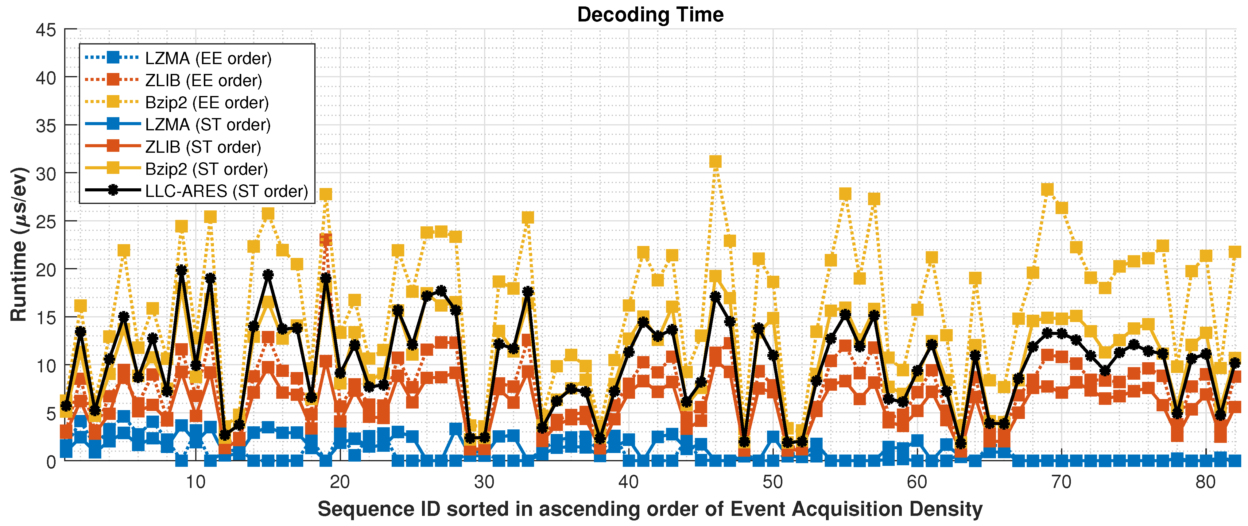
4.3. Runtime Results
- (i)
- an average event density improvement of , and respectively; and
- (ii)
- an average TR improvement of and respectively.
4.4. RA Results
5. Conclusions
- (1)
- an average CR improvement of , , and
- (2)
- an average BR improvement of and
- (3)
- an average bitsavings of bpev, bpev, and bpev;
- (4)
- an average event density improvement of , and and
- (5)
- an average TR improvement of and .
Author Contributions
Funding
Institutional Review Board Statement
Informed Consent Statement
Data Availability Statement
Conflicts of Interest
Abbreviations
| DVS | Dynamic Vision Sensor |
| APS | Active Pixel Sensor |
| DAVIS | Dynamic and Active-pixel VIsion Sensor |
| EF | Event Frame |
| RA | Random Access |
| TALVEN | Time Aggregation-based Lossless Video Encoding for Neuromorphic sensor |
| ESP | Event Signal Processing |
| SoC | System-on-a-chip |
| EMI | Event Map Image |
| CPV | Concatenated Polarity Vector |
| HEVC | High Efficiency Video Coding |
| SNN | Spike Neural Network |
| EGC | Elias-Gamma-Coding |
| LLC-ARES | Low-Complexity Lossless AsynchRonous Event Sequences |
| LLC-ARES-RA | LLC-ARES with RA |
| ZLIB | Zeta Library |
| LZMA | Lempel–Ziv–Markov chain Algorithm |
| G-PCC | Geometry-based Point Cloud Compression |
| CR | Compression Ratio |
| BR | Bitrate |
| TR | Time Ratio |
References
- Lichtsteiner, P.; Posch, C.; Delbruck, T. A 128× 128 120 dB 15 μs Latency Asynchronous Temporal Contrast Vision Sensor. IEEE J. Solid State Circ. 2008, 43, 566–576. [Google Scholar] [CrossRef]
- Brandli, C.; Berner, R.; Yang, M.; Liu, S.C.; Delbruck, T. A 240 × 180 130 dB 3 µs Latency Global Shutter Spatiotemporal Vision Sensor. IEEE J. Solid State Circ. 2014, 49, 2333–2341. [Google Scholar] [CrossRef]
- Pan, L.; Scheerlinck, C.; Yu, X.; Hartley, R.; Liu, M.; Dai, Y. Bringing a Blurry Frame Alive at High Frame-Rate With an Event Camera. In Proceedings of the 2019 IEEE/CVF Conference on Computer Vision and Pattern Recognition (CVPR), Long Beach, CA, USA, 15–20 June 2019; pp. 6813–6822. [Google Scholar] [CrossRef]
- Gehrig, D.; Rebecq, H.; Gallego, G.; Scaramuzza, D. EKLT: Asynchronous Photometric Feature Tracking using Events and Frames. Int. J. Comput. Vis. 2020, 128, 601–618. [Google Scholar] [CrossRef]
- Iaboni, C.; Lobo, D.; Choi, J.W.; Abichandani, P. Event-Based Motion Capture System for Online Multi-Quadrotor Localization and Tracking. Sensors 2022, 22, 3240. [Google Scholar] [CrossRef] [PubMed]
- Zhu, A.; Yuan, L.; Chaney, K.; Daniilidis, K. EV-FlowNet: Self-Supervised Optical Flow Estimation for Event-based Cameras. In Proceedings of the Robotics: Science and Systems, Pittsburgh, PA, USA, 26–30 June 2018. [Google Scholar] [CrossRef]
- Brandli, C.; Mantel, T.; Hutter, M.; Höpflinger, M.; Berner, R.; Siegwart, R.; Delbruck, T. Adaptive pulsed laser line extraction for terrain reconstruction using a dynamic vision sensor. Front. Neurosci. 2014, 7, 1–9. [Google Scholar] [CrossRef]
- Li, S.; Feng, Y.; Li, Y.; Jiang, Y.; Zou, C.; Gao, Y. Event Stream Super-Resolution via Spatiotemporal Constraint Learning. In Proceedings of the 2021 IEEE/CVF International Conference on Computer Vision (ICCV), Montreal, QC, Canada, 11 October 2021; pp. 4460–4469. [Google Scholar] [CrossRef]
- Yu, Z.; Zhang, Y.; Liu, D.; Zou, D.; Chen, X.; Liu, Y.; Ren, J. Training Weakly Supervised Video Frame Interpolation with Events. In Proceedings of the 2021 IEEE/CVF International Conference on Computer Vision (ICCV), Montreal, QC, Canada, 10–17 October 2021; pp. 14569–14578. [Google Scholar] [CrossRef]
- Wang, Y.; Yang, J.; Peng, X.; Wu, P.; Gao, L.; Huang, K.; Chen, J.; Kneip, L. Visual Odometry with an Event Camera Using Continuous Ray Warping and Volumetric Contrast Maximization. Sensors 2022, 22, 5687. [Google Scholar] [CrossRef]
- Gallego, G.; Delbrück, T.; Orchard, G.; Bartolozzi, C.; Taba, B.; Censi, A.; Leutenegger, S.; Davison, A.; Conradt, J.; Daniilidis, K.; et al. Event-Based Vision: A Survey. IEEE Trans. Pattern Anal. Mach. Intell. 2022, 44, 154–180. [Google Scholar] [CrossRef]
- Bi, Z.; Dong, S.; Tian, Y.; Huang, T. Spike Coding for Dynamic Vision Sensors. In Proceedings of the Data Compression Conf., Snowbird, UT, USA, 27–30 March 2018; pp. 117–126. [Google Scholar] [CrossRef]
- Dong, S.; Bi, Z.; Tian, Y.; Huang, T. Spike Coding for Dynamic Vision Sensor in Intelligent Driving. IEEE Internet Things J. 2019, 6, 60–71. [Google Scholar] [CrossRef]
- Khan, N.; Iqbal, K.; Martini, M.G. Lossless Compression of Data From Static and Mobile Dynamic Vision Sensors-Performance and Trade-Offs. IEEE Access 2020, 8, 103149–103163. [Google Scholar] [CrossRef]
- Khan, N.; Iqbal, K.; Martini, M.G. Time-Aggregation-Based Lossless Video Encoding for Neuromorphic Vision Sensor Data. IEEE Internet Things J. 2021, 8, 596–609. [Google Scholar] [CrossRef]
- Banerjee, S.; Wang, Z.W.; Chopp, H.H.; Cossairt, O.; Katsaggelos, A.K. Lossy Event Compression Based On Image-Derived Quad Trees And Poisson Disk Sampling. In Proceedings of the IEEE International Conference on Image Processing, Imaging without Borders, Anchorage, AK, USA, 19–22 September 2021; pp. 2154–2158. [Google Scholar] [CrossRef]
- Schiopu, I.; Bilcu, R.C. Lossless Compression of Event Camera Frames. IEEE Signal Process. Lett. 2022, 29, 1779–1783. [Google Scholar] [CrossRef]
- Schiopu, I.; Bilcu, R.C. Low-Complexity Lossless Coding for Memory-Efficient Representation of Event Camera Frames. IEEE Sens. Lett. 2022, 6, 1–4. [Google Scholar] [CrossRef]
- Elias, P. Universal codeword sets and representations of the integers. IEEE Trans. Inf. Theory 1975, 21, 194–203. [Google Scholar] [CrossRef]
- Ziv, J.; Lempel, A. A universal algorithm for sequential data compression. IEEE Trans. Inf. Theory 1977, 23, 337–343. [Google Scholar] [CrossRef]
- Deutsch, P.; Gailly, J.L. Zlib Compressed Data Format Specification; Version 3.3; RFC: 1950; IETF. 1996. Available online: https://www.ietf.org/ (accessed on 19 July 2021).
- Pavlov, I. LZMA SDK (Software Development Kit). Available online: https://www.7-zip.org/ (accessed on 19 July 2021).
- Burrows, M.; Wheeler, D.J. A Block-Sorting Lossless Data Compression Algorithm; IEEE: Piscataway, NJ, USA, 1994. [Google Scholar]
- Martini, M.G.; Adhuran, J.; Khan, N. Lossless Compression of Neuromorphic Vision Sensor Data based on Point Cloud Representation. IEEE Access 2022, 10, 121352–121364. [Google Scholar] [CrossRef]
- Henri Rebecq, T.H.; Scaramuzza, D. Real-time Visual-Inertial Odometry for Event Cameras using Keyframe-based Nonlinear Optimization. In Proceedings of the British Machine Vision Conference (BMVC), London, UK, 21–24 November 2017; Tae-Kyun, K., Stefanos Zafeiriou, G.B., Mikolajczyk, K., Eds.; BMVA Press: Durham, UK; pp. 16.1–16.12. [Google Scholar] [CrossRef]
- Maqueda, A.I.; Loquercio, A.; Gallego, G.; Garcia, N.; Scaramuzza, D. Event-Based Vision Meets Deep Learning on Steering Prediction for Self-Driving Cars. In Proceedings of the 2018 IEEE/CVF Conference on Computer Vision and Pattern Recognition, Salt Lake City, UT, USA, 18–23 June 2018; IEEE: Piscataway, NJ, USA. [Google Scholar] [CrossRef]
- Almatrafi, M.; Baldwin, R.; Aizawa, K.; Hirakawa, K. Distance Surface for Event-Based Optical Flow. IEEE Trans. Pattern Anal. Mach. Intell. 2020, 42, 1547–1556. [Google Scholar] [CrossRef]
- Benosman, R.; Clercq, C.; Lagorce, X.; Ieng, S.H.; Bartolozzi, C. Event-Based Visual Flow. IEEE Trans. Neural Netw. Learn. Syst. 2014, 25, 407–417. [Google Scholar] [CrossRef]
- Zhu, A.; Yuan, L.; Chaney, K.; Daniilidis, K. Unsupervised Event-Based Learning of Optical Flow, Depth, and Egomotion. In Proceedings of the 2019 IEEE/CVF Conference on Computer Vision and Pattern Recognition (CVPR), Los Alamitos, CA, USA, 15–20 June 2019; IEEE Computer Society: Washington, DC, USA, 2019; pp. 989–997. [Google Scholar] [CrossRef]
- Baldwin, R.; Liu, R.; Almatrafi, M.M.; Asari, V.K.; Hirakawa, K. Time-Ordered Recent Event (TORE) Volumes for Event Cameras. IEEE Trans. Pattern Anal. Mach. Intell. 2022; Early Access. [Google Scholar] [CrossRef]
- Sullivan, G.J.; Ohm, J.R.; Han, W.J.; Wiegand, T. Overview of the High Efficiency Video Coding (HEVC) Standard. IEEE Trans. Circ. Syst. Video Technol. 2012, 22, 1649–1668. [Google Scholar] [CrossRef]
- Zhu, L.; Dong, S.; Huang, T.; Tian, Y. Hybrid Coding of Spatiotemporal Spike Data for a Bio-Inspired Camera. IEEE Trans. Circ. Syst. Video Technol. 2021, 31, 2837–2851. [Google Scholar] [CrossRef]
- Gehrig, M.; Aarents, W.; Gehrig, D.; Scaramuzza, D. DSEC: A Stereo Event Camera Dataset for Driving Scenarios. IEEE Robot. Autom. Lett. 2021, 6, 4947–4954. [Google Scholar] [CrossRef]
- DSEC Dataset. Available online: https://dsec.ifi.uzh.ch/dsec-datasets/download/ (accessed on 1 October 2021).
- Vollan, G. ZLIB Pre-Build DLL. Available online: http://www.winimage.com/zLibDll/ (accessed on 19 July 2021).
- Seward, J. bzip2 Pre-Build Binaries. Available online: http://gnuwin32.sourceforge.net/packages/bzip2.htm (accessed on 19 July 2021).


| Method | ZLIB [35] | LZMA [22] | bzip2 [36] | Proposed LLC-ARES | |
|---|---|---|---|---|---|
| CR | EE order | 2.21 | 3.51 | 2.11 | – |
| ST order | 3.22 | 3.92 | 4.14 | 4.3 | |
| EBR (bpev) | EE order | 29.65 | 18.91 | 30.50 | – |
| ST order | 20.32 | 16.80 | 15.91 | 14.8 | |
| (Mevps) | ST order | 1.392 | 0.275 | 2.453 | 5.736 |
| TR | ST order | 0.133 | 0.027 | 0.246 | 0.531 |
| Method | ZLIB [35] | LZMA [22] | bzip2 [36] | Proposed LLC-ARES | |
|---|---|---|---|---|---|
| Encoding Runtime | EE order | 67.20 s/ev | 210.39 s/ev | 40.91 s/ev | – |
| ST order | 44.70 s/ev | 227.27 s/ev | 25.75 s/ev | 10.92 s/ev | |
| Decoding Runtime | EE order | 0.78 s/ev | 7.46 s/ev | 16.09 s/ev | – |
| ST order | 1.14 s/ev | 5.71 s/ev | 10.58 s/ev | 10.21 s/ev | |
Publisher’s Note: MDPI stays neutral with regard to jurisdictional claims in published maps and institutional affiliations. |
© 2022 by the authors. Licensee MDPI, Basel, Switzerland. This article is an open access article distributed under the terms and conditions of the Creative Commons Attribution (CC BY) license (https://creativecommons.org/licenses/by/4.0/).
Share and Cite
Schiopu, I.; Bilcu, R.C. Low-Complexity Lossless Coding of Asynchronous Event Sequences for Low-Power Chip Integration. Sensors 2022, 22, 10014. https://doi.org/10.3390/s222410014
Schiopu I, Bilcu RC. Low-Complexity Lossless Coding of Asynchronous Event Sequences for Low-Power Chip Integration. Sensors. 2022; 22(24):10014. https://doi.org/10.3390/s222410014
Chicago/Turabian StyleSchiopu, Ionut, and Radu Ciprian Bilcu. 2022. "Low-Complexity Lossless Coding of Asynchronous Event Sequences for Low-Power Chip Integration" Sensors 22, no. 24: 10014. https://doi.org/10.3390/s222410014
APA StyleSchiopu, I., & Bilcu, R. C. (2022). Low-Complexity Lossless Coding of Asynchronous Event Sequences for Low-Power Chip Integration. Sensors, 22(24), 10014. https://doi.org/10.3390/s222410014