Abstract
Centimeter level augmentation system (CLAS) of the quasi-zenith satellite system (QZSS) is the first precise point positioning-real time kinematic (PPP-RTK) augmentation system of the global navigation satellite system (GNSS), which is currently providing services for Japan. CLAS broadcasts the state-space representation of correction messages along with integrity messages regarding satellite faults and the quality index of each correction. In other GNSS augmentation systems, such as the space-based augmentation system (SBAS) of GNSS, the quality indices of correction messages are used to generate fault-free protection levels that represent a position bound containing a true user position with a probability of missed detections. Although the protection level equations are well defined for the SBAS, a protection level equation for the CLAS PPP-RTK service has not been rigorously discussed in the literature. This paper proposes a fault-free protection level equation for the PPP-RTK methods that considers the probability of correct integer ambiguity fixes in the GNSS carrier phase measurements as well as the CLAS correction quality messages. The computed protection levels with position errors were experimentally compared by processing the GNSS measurements from the GNSS Earth Observation Network (GEONET) stations in Japan and the L6 messages from the CLAS broadcast using the virtual reference station-real time kinematic (VRS-RTK) techniques. Our results, based on the GEONET dataset spanning 7 days, showed that the computed protection levels using the proposed equations were larger than the position errors for all epochs. In the dataset, the RMS errors of the CLAS VRS-RTK position were 4.6 and 14 cm in the horizontal and vertical directions, respectively, whereas the horizontal protection levels ranged from 25 cm to 2.3 m and the vertical protection levels ranged from 50 cm to 5.2 m based on fault-free integrity risk of .
1. Introduction
The performance of the global navigation satellite system (GNSS) is enhanced by differential GNSS techniques, including ground- and space-based augmentation systems (GBAS and SBAS) of the global positioning system (GPS) [1,2]. The GBAS and SBAS were primarily developed to guide aircraft navigation, and their design approach and operational philosophies centered on system safety. The safety levels of GBAS and SBAS are quantized as system integrity measures, and one of the important integrity measures is a protection level [3,4]. The protection level represents the bound of the true position error at the risk of a missed-detection probability. In GBAS and SBAS, a position bound is computed using the well-defined protection level equations that transform the range-domain Gaussian error distributions of each visible satellite to the position-domain Gaussian error distributions via a user-to-satellite geometry. The range-domain error distributions used in the protection level equations are determined by the GBAS and SBAS service providers and are broadcast to users as quality indicators associated with each correction message. An important characteristic of the range domain error distribution is to overbound the actual error distribution of the correction messages in order for the protection levels, computed using the quality indicators, to overbound the actual user position errors with a missed-detection probability. Consequently, studies have been conducted on various overbounding techniques based on probability density function (PDF), cumulative distribution function (CDF), and paired overbounding [5,6,7,8].
Centimeter level augmentation system (CLAS) of the quasi-zenith satellite system (QZSS) is a very recent GNSS augmentation system of Japan [9,10,11]. Unlike the GBAS and SBAS, which primarily use the GNSS code phase measurements as ranging sources, CLAS is a precise point positioning–real-time kinematic (PPP-RTK) augmentation system that allows users to resolve integer ambiguities in carrier phase measurements within several minutes by using the CLAS correction messages. Therefore, the CLAS users can use the carrier phase as a ranging source and achieve precise positioning similar to that of RTK. CLAS also provides quality indicators (also called integrity messages) for each correction message so that the users can compute the protection levels. However, the CLAS protocol currently does not specify any forms of protection-level equations, and quality message generation schemes are not well known [12,13]. Owing to lack of information, the CLAS users are not encouraged to rely on the quality messages for safe navigation.
Unfortunately, the protection level equations of GBAS or SBAS cannot be directly applied to the CLAS PPP-RTK position solutions, because GBAS or SBAS do not use the carrier phase as ranging sources. Previous studies have proposed protection-level equations for PPP and RTK that use the carrier phase as ranging sources [14,15,16,17,18,19]. These studies were based on receiver autonomous integrity monitoring (RAIM) [20], and their protection levels were derived to protect against the hard-to-detect faults in ranging measurements and cycle slips. Feng proposed a Kalman filter-based RAIM for the carrier phase [14]. In this approach, the de-correlated innovations of the Kalman filter were used to detect faults. Protection levels were computed either from the covariance matrix of the Kalman filter or from using the geometry of the satellite whose faults would be most difficult to detect. References [15,16] proposed isotropy-based protection levels (IBPL), particularly designed for the PPP position solutions. Assumptions regarding the behavior of ranging errors in terms of their size, direction, and protection levels as derived from a multivariate t-distribution of measurement errors were not made in IBPL. Ahmed et al. proposed protection levels for RTK, which were modelled in a modified form from the solution-separation RAIM methods [17,18]. An integrity risk in this approach considers the mutually exclusive events of correct and incorrect ambiguity resolutions in the least-squares ambiguity decorrelation adjustment (LAMBDA) method, which was introduced in [19]. Although these studies can be applied to derive protection levels for the CLAS PPP-RTK position solutions, their protection levels would be relatively larger because they do not use the CLAS integrity messages or the fault monitoring capability of the CLAS network.
This paper proposes a protection-level equation for the PPP-RTK services broadcasting quality messages. Because both PPP-RTK and SBAS broadcast state space representation (SSR) of the correction messages, our proposed protection level equations are based on the SBAS protection level equations and are extended to reflect virtual reference station (VRS)-RTK positioning scheme, which is a method of processing the PPP-RTK correction messages on the user side. Additionally, the integrity messages of the CLAS service are assumed to have a standard deviation of a Gaussian distribution, similar to the SBAS. This study compared the protection levels computed using the CLAS integrity messages with the VRS-RTK position errors. For the VRS-RTK process, we used CLAS L6 messages and GNSS observation measurements from the GNSS Earth Observation Network (GEONET) station in Japan. The L6 integrity messages were only used to compute the protection levels, because they were significantly inflated from the actual error distribution of the correction messages; however, the VRS-RTK process used the correction error distributions used in practice, whose standard deviation was significantly smaller than that of the integrity messages.
This paper provides an overview of the architecture of CLAS and broadcasting messages in Section 2. Section 3 discusses the proposed protection-level equations for PPP-RTK. Section 4 presents examples of broadcast integrity indices and computed horizontal and vertical protection levels with the dataset. Finally, the discussion and conclusions are presented.
2. Overview of the CLAS Broadcast Messages
CLAS receives the GNSS observation data from approximately 1200 GEONET stations and processes the data to generate the correction and integrity messages in a Compact SSR format. The Compact SSR messages are broadcast through the L6 band by the QZSS and are defined as RTCM 3 compatible proprietary message type 4073 [13]. The Compact SSR messages have 12 subtypes consisting of correction and integrity information, and the message types are listed in Table 1 [21]. The correction messages for the orbit, clock, code bias, and phase bias are called common corrections. The zenith tropospheric delay and slant ionospheric delay for each GNSS are referred to as local corrections.

Table 1.
Compact SSR message type, nominal validity period, and nominal update interval.
Among the message subtype IDs, the quality messages are included in subtype IDs 7, 8, 9, and 12. Subtype ID 7 provides a quality indicator for the user range accuracy (URA) of each satellite, and others provide a troposphere quality indicator as well as an SSR slant total electron content (STEC) quality indicator. The quality indicator is represented by a combination of CLASS and VALUE, the values of which range from 0 to 7, as seen in Equation (1). The SSR URA and tropospheric quality indicators were converted to a physical quantity using the following Equation [21]:
The SSR STEC physical quantity was read from a table relating the SSR STEC quality indicators to the SSR STEC correction uncertainty.
The total ranging error for ith satellite can be estimated by the following equation
where is a user-specific local error, such as multipath errors. is a signal in space error representing the correction message uncertainty of the orbit, clock, code, and carrier biases. is the ionospheric delay correction uncertainty provided from the STEC correction quality indicator in total electron content unit (TECU). represent the troposphere delay correction uncertainty. is the frequency of the GNSS signal and is the satellite elevation angle. The total ranging error is calculated in centimeters, which is why both and divided by 10 is used, and the same applies for . Some examples of the CLAS broadcast quality indicators are presented in Section 4.
3. Proposed Fault-Free Protection Level Equations for CLAS PPP-RTK Service
To develop a fault-free protection-level equation for a PPP-RTK system, the current protection-level equations of SBAS are used as the baseline equations because both SBAS and PPP-RTK broadcast the correction and quality messages in SSR formats. This section provides an overview of the SBAS fault-free protection level equation, followed by the proposed PPP-RTK protection level equation.
3.1. Fault-Free Protection Level Equations of SBAS
The SBAS L1 frequency-only protection-level equation uses the broadcast correction message uncertainties and user-defined multipath and noise uncertainties. For an individual SBAS pseudo range error, the combined range error variance for the ith satellite was constructed as follows:
where is the variance of the fast and long-term satellite clock error corrections. is the variance of the user ionosphere range error correction, and is the variance of the tropospheric error correction, and is the variance of the multipath error excluding multipath from ground. It should be noted that each variance is determined from a zero-mean Gaussian distribution that overbounds a non-ideal Gaussian distribution of correction errors.
The pseudo range variance is used as a weighting matrix to compute an SBAS position solution such that
The direction vector from a user to satellite can be formulated as
Then, the standard deviation of the position estimate uncertainty in East/North/Up (ENU) coordinates is
With a missed-detection probability and its corresponding Gaussian tail value of , the vertical protection level (VPL) bounding vertical position errors is
Similarly, the horizontal protection level (HPL) is computed.
3.2. Overview of Least-Squares Ambiguity Decorrelation Adjustment (LAMBDA)
The PPP-RTK service allows the use of the GNSS carrier phase for ranging measurements in a manner similar to a VRS-RTK process. A VRS-RTK process typically resolves the integer ambiguities in carrier phase measurements using the LAMBDA algorithm [22,23], and its upper bound probability of correctly fixing integer ambiguities is assessed using the integer bootstrapping method [24].
With GNSS measurements of the two receivers at a short baseline, the basic observation measurements are as follows:
where and are the double-difference code and carrier-phase measurements, respectively. is the geometric range from a user to a satellite. is the frequency wavelength of a GNSS carrier. is integer ambiguity. represents the uncorrected range measurements and noise. The linearized observation equation for a set of double-difference codes and carrier-phase measurements of visible satellites is
where is a vector of the double-difference code and carrier-phase measurements. is a vector of integer ambiguities and is a corresponding matrix with wavelengths as elements. is a satellite geometry matrix, and is the relative position vector from a VRS reference position to a GNSS receiver.
The popular LAMBDA method resolves and computes the precise in two steps. First, an unconstrained solution of Equation (10) is computed as
where and are the estimated baseline and float-integer ambiguities, respectively. is the covariance matrix of in Equation (10). The covariance matrix of and is
The second procedure of LAMBDA consists of the re-parameterization and search for . The re-parameterization of the integer vector is implemented as follows:
where is the decorrelation transformation matrix. Then, the re-parameterized integer ambiguity is searched with respect to the following objective function:
Once an optimal integer ambiguity vector, , is obtained from Equation (14), the original integer ambiguity vector estimate is obtained using the inverse of the transformation such that
The presumed fixed baseline vector, is
In addition, the covariance matrix of is as follows:
where and are the covariance matrices of the double-difference code and the carrier-phase measurements, respectively.
3.3. Proposed Fault-Free PPP-RTK Protection Level Equation
The integer ambiguity resolution through LAMBDA is a stochastic search process, and based on the bias-free estimates of float ambiguities, its upper bound probability of correct integer fixes is [24]
where is the conditional least-squares estimate of integer ambiguity. Because the correctness of the fixed integer ambiguities may significantly affect the position errors, the probability of Equation (18) must be considered in a protection-level equation. A protection level (XPL) and given fault-free risk probability () can be expressed as follows:
where and denote the estimated position and true position, respectively, in the horizontal or vertical directions. refers to the horizontal or vertical protection levels. Because the position error may exceed with correctly fixed (CF) or incorrectly fixed (IF) integer ambiguities, Equation (19) can be expanded to two conditional probabilities, as follows [9]:
where is the probability of the correct fix, which can be estimated from Equation (18). PIF is the probability of incorrect fix and equals to .
Considering as a conservative approach, the fault-free risk probability presuming that integer ambiguities are correctly fixed is
Assuming that the position error follows a zero-mean Gaussian distribution, the corresponding tail value of Equation (21) was used as the factor in Equation (7).
Using the total range error of CLAS, , in Equation (2), a weighting matrix for a single-differenced ranging source can be similarly constructed as in Equation (4). Because VRS-RTK uses double-difference code and carrier phase measurements, and in Equation (17) can be expressed as
where is the double-difference matrix. Using the derived from Equation (21) and substituting Equation (23) into Equation (17), the fault-free horizontal and vertical protection level equations were computed as follows:
In Equation (23), is evaluated in ENU coordinates.
4. Evaluation of the Proposed Protection Levels for PPP-RTK
This section discusses the GNSS observation data and parsing process of the CLAS L6 broadcast messages used in this study. Subsequently, the resultant positioning error of the VRS-RTK positioning and computed protection levels are presented.
4.1. Experimental Data Processing
To evaluate the performance of the proposed protection level, we used the GNSS observation data provided by the website of the Geospatial Information Authority of Japan [25] and the L6 data provided by the website of the QZSS [26]. CLASLIB, an open-source software tool [26], was used to extract quality messages from the L6 broadcast data and generate the GNSS measurements for the VRS-RTK process.
CLASLIB is an open-source library that parses the CLAS L6 messages, and the process is shown in Figure 1. It converts the CLAS L6 messages to the observation space representation of correction messages or provides parsed L6 message Type 4073 in comma-separated value formats. CLASLIB can also generate VRS-RTK GNSS observation data from the given GNSS navigation data and the corresponding L6 broadcast messages.
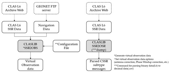
Figure 1.
Data extraction of CLAS L6 broadcast messages using CLASLIB.
To evaluate the proposed protection-level equations, GNSS data were obtained from a GEONET base station located in Chiyoda City, Tokyo, Japan, as shown in Figure 2. The test site is located within the CLAS service volume. The GNSS dataset consisted of the GPS and Galileo RINEX observation and navigation files collected over 7 days from 00:00:00 on 11 April 2021, to 23:59:30 on 17 April 2021, with 30 s intervals. The base station uses a Trimble NETR9 receiver and a Trimble TPSCR.G5C antenna. The numbers of visible GPS and Galileo satellites during this period are shown in Figure 3. Because the satellite constellation exhibits a trend similar to that of a daily cycle, only the number of visible satellites in 1 day is shown. Figure 4 and Figure 5 show the time series of the and , respectively, extracted from the dataset. Figure 6 shows the time series of the for the GPS and Galileo satellites. The user receiver multipath and noise uncertainty of the code and carrier-phase measurements are modelled as in centimeters and in millimeters, respectively, and are the typically used values.
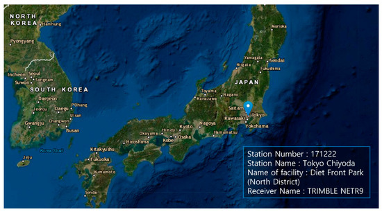
Figure 2.
GNSS data obtained from a GEONET base station located at Chome-1 Nagatacho, Chiyoda City, Tokyo 100-0014, Japan (35.677° latitude and 139.748° longitude) [27].
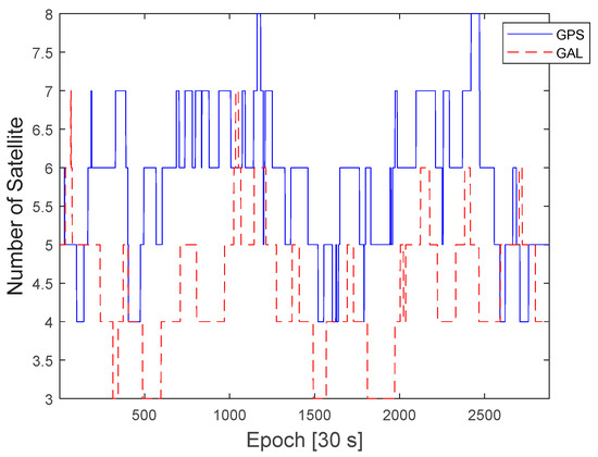
Figure 3.
Number of visible GPS and Galileo satellites during a day in the 7-day period.
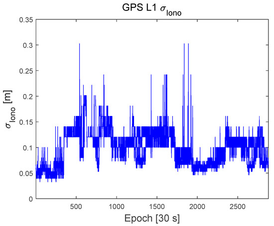
Figure 4.
Time series of the Ionospheric correction quality, , in meters.
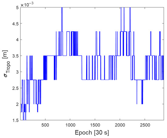
Figure 5.
Time series of the Troposphere correction quality, , in meters.
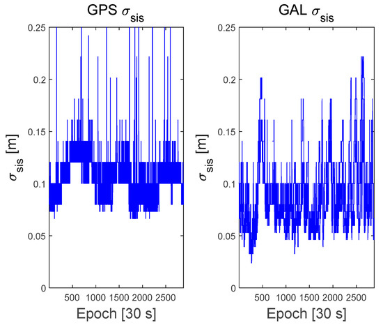
Figure 6.
Time series of the Signal in Space correction quality, , for GPS and Galileo satellites.
4.2. Comparison of the VRS-RTK Position Errors and Computed Protection Levels
Figure 7 shows the resultant ENU position errors of zero-baseline VRS-RTK using dual-frequency GPS and Galileo satellites with the test dataset. To determine the fixed integers, a conventional test value ratio, above 3, was used. The RMS of the positioning errors with the fixed integers is 4, 2, and 14 cm in the East, North, and up directions, respectively. At certain epochs, our VRS-RTK software failed to resolve fixed integers due to cycle slips. For this particular test, 2.5% of the data contained a float solution.
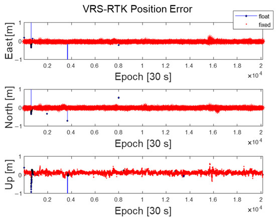
Figure 7.
VRS−RTK position errors for float and fixed integer cases with the test dataset.
Figure 8 and Figure 9 show the computed protection levels and the position errors for the fixed integers cases with a fault-free risk probability () of 10−7. If the test value ratio was less than 3, that is, float solutions, no protection levels were computed. As shown in Figure 8 and Figure 9, all of the computed HPL and VPL were larger than the horizontal positioning errors (HPE) and vertical positioning errors (VPE), respectively. The RMS of the HPE was 4.6 cm whereas that of the HPL ranged from 25 cm to 2.3 m. The RMS of the VPE was 14 cm, whereas the VPL ranged from 50 cm to 5.2 m. At certain epochs, there are large peaks in the HPL and VPL, and these peaks occur when there is a jump in quality indices. These large protection levels occurred at very small percentages such that HPL was less than 1 m in 99.4% and VPL was less than 3 m in 99.6% of the dataset, respectively.
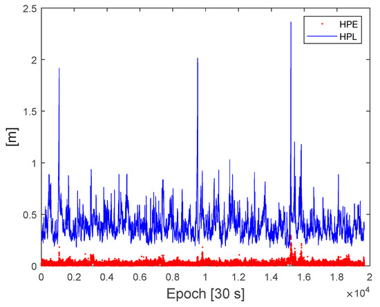
Figure 8.
Comparison of the horizontal protection levels and horizontal position errors from the test dataset.
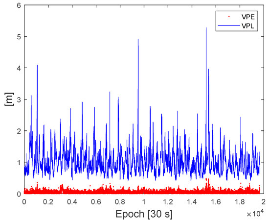
Figure 9.
Comparison of the vertical protection levels and vertical position errors from the test dataset.
5. Discussion
The broadcast of the correction messages in SBAS or CLAS is typically much larger than the actual correction error distribution because it is intentionally inflated to overbound the residual errors in range measurements such that the protection levels also overbound the position errors after applying the correction messages. In VRS-RTK, the uncertainty of the double-difference code and carrier phase measurement, and , respectively, is used to solve the float baseline and integer ambiguities. Then, the float integer ambiguities and their associated covariance matrices are used in the re-parameterization and search procedure for integer ambiguities. If and are constructed using the broadcasted from CLAS, the LAMBDA process has a very large search space and a high chance of finding incorrect integer ambiguities. Therefore, the realistic values of and should be used to successfully resolve the integer ambiguities in LAMBDA.
In the test results, the RMS errors in the up direction are relatively larger than in the East and North directions. The mean value of the vertical position errors had a bias of approximately 12 cm. We also observed a similar bias from zero-baseline VRS-RTK position errors with the same dataset using an open-source software tool [28]. Therefore, it is presumed that there was a bias in the reported true antenna positions of the GNSS dataset used in the test. This issue will be investigated further.
In fact, whether the receiver moves or not, protection levels can be computed in the same way as long the PPP-RTK process is adequately implemented. However, a dynamic receiver may suffer from a frequent loss and inclusion of satellites, which may overall lower the PCF of integer ambiguities and result in incorrect integer ambiguities. The research on this issue will also be carried out as future work.
6. Conclusions
This paper presents a fault-free protection level equation for the CLAS PPP-RTK service that broadcasted correction quality messages. The performance of the proposed protection level equations was tested using 7 days of the GNSS observation data and the CLAS L6 messages obtained at a base station in Tokyo, Japan, which was located within the CLAS service region. The test results with 7 days of GNSS data showed that the HPL and VPL were always larger than the HPE and VPE of the zero-baseline VRS-RTK solution. Furthermore, fault-free protection-level violations were not observed. It should be noted that most HPL and VPL values were less than 1 and 3 m, respectively. Since a rail automation, which is a very demanding problem from an integrity point of view, requires Horizontal Alert Limit of 1m [29], the proposed protection level would be able to fulfill stringent integrity and availability requirements for many applications using PPP-RTK services.
Author Contributions
Protection-level equation development, E.K.; GNSS and CLAS data processing, J.S., Y.S. and S.K.; validation, P.-W.S., S.P. (Sulgee Park) and S.P. (Sanghyun Park). All authors have read and agreed to the published version of the manuscript.
Funding
This research was part of the project titled “Development of Ground-based Centimeter-level Maritime Precise PNT Technologies”, funded by the Ministry of Oceans and Fisheries, Korea (No. PMS5110). This work was also supported by a National Research Foundation of Korea (NRF) grant funded by the Korean government (MSIT) (No. 2020R1A2C2006028).
Acknowledgments
The authors thank Chanhee Lee for his help with the preparation of this paper.
Conflicts of Interest
The authors declare no conflict of interest.
References
- Pervan, B. Ground-Based Augmentation System. In Position, Navigation, and Timing Technologies in the 21st Century: Integrated Satellite Navigation, Sensor Systems, and Civil Applications, Volume 1; Wiley: Hoboken, NJ, USA, 2020; pp. 259–276. [Google Scholar]
- Walter, T. Satellite Based Augmentation Systems. In Springer Handbook of Global Navigation Satellite Systems; Springer: Cham, Switzerland, 2017; pp. 339–361. [Google Scholar]
- Pullen, S.; Walter, T.; Enge, P. SBAS and GBAS Integrity for Non-Aviation Users: Moving Away from “Specific Risk”. In Proceedings of the 2011 International Technical Meeting of The Institute of Navigation, San Diego, CA, USA, 24–26 January 2011; pp. 533–545. [Google Scholar]
- Pullen, S. Augmented GNSS: Fundamentals and Keys to Integrity and Continuity. Available online: http://www-leland.stanford.edu/~spullen/ION12_tutorial.pdf (accessed on 25 March 2022).
- DeCleene, B. Defining Pseudorange Integrity-Overbounding. In Proceedings of the 13th International Technical Meeting of the Satellite Division of The Institute of Navigation (ION GPS 2000), Salt Lake City, UT, USA, 19–22 September 2000; pp. 1916–1924. [Google Scholar]
- Rife, J.; Pullen, S.; Pervan, B.; Enge, P. Paired Overbounding and Application to GPS Augmentation. In Proceedings of the PLANS 2004. Position Location and Navigation Symposium (IEEE Cat. No.04CH37556), Monterey, CA, USA, 26–29 April 2004; pp. 439–446. [Google Scholar]
- Rife, J.; Pullen, S.; Pervan, B. Core Overbounding and Its Implications for LAAS Integrity. In Proceedings of the 17th International Technical Meeting of the Satellite Division of The Institute of Navigation (ION GNSS 2004), Long Beach, CA, USA, 21–24 September 2004; pp. 2810–2821. [Google Scholar]
- Walter, T.; Blanch, J.; Rife, J. Treatment of Biased Error Distributions in SBAS. J. Glob. Position. Syst. 2004, 3, 265–272. [Google Scholar] [CrossRef][Green Version]
- Miya, M.; Fujita, S.; Sato, Y.; Ota, K.; Hirokawa, R.; Takiguchi, J. Centimeter Level Augmentation Service (CLAS) in Japanese Quasi-Zenith Satellite System, Its User Interface, Detailed Design, and Plan. In Proceedings of the 29th International Technical Meeting of the Satellite Division of The Institute of Navigation (ION GNSS+ 2016), Portland, OR, USA, 12–16 September 2016; pp. 2864–2869. [Google Scholar]
- Miya, M.; Fujita, S.; Sato, Y.; Kaneko, K.; Shima, Y.; Hirokawa, R.; Sone, H.; Takiguchi, J. Centimeter Level Augmentation Service (CLAS) in Japanese Quasi-Zenith Satellite System, Design for Satellite Based RTK-PPP Services. In Proceedings of the 28th International Technical Meeting of the Satellite Division of The Institute of Navigation (ION GNSS+ 2015), Tampa, FL, USA, 14–18 September 2015; pp. 1958–1962. [Google Scholar]
- Miya, M.; Sato, Y.; Fujita, S.; Motooka, N.; Saito, M.; Takiguchi, J. Centimeter Level Augmentation Service (CLAS) in Japaneses Quasi-Zenith Satellite System, Its Preliminary Design and Plan. In Proceedings of the 27th International Technical Meeting of the Satellite Division of The Institute of Navigation (ION GNSS+ 2014), Tampa, FL, USA, 8–12 September 2014; pp. 645–652. [Google Scholar]
- Fujita, S.; Sato, Y.; Miya, M.; Ota, K.; Hirokawa, R.; Takiguchi, J. Design of Integrity Function on Centimeter Level Augmentation Service (CLAS) in Japanese Quasi-Zenith Satellite System. In Proceedings of the 29th International Technical Meeting of the Satellite Division of The Institute of Navigation (ION GNSS+ 2016), Portland, OR, USA, 12–16 September 2016; pp. 3258–3263. [Google Scholar]
- Hirokawa, R.; Sato, Y.; Fujita, S.; Miya, M. Compact SSR Messages with Integrity Information for Satellite Based PPP-RTK Service. In Proceedings of the 29th International Technical Meeting of the Satellite Division of The Institute of Navigation (ION GNSS+ 2016), Portland, OR, USA, 12–16 September 2016; pp. 3372–3376. [Google Scholar]
- Feng, S.; Ochieng, W.; Moore, T.; Hill, C.; Hide, C. Carrier Phase-Based Integrity Monitoring for High-Accuracy Positioning. GPS Solut. 2009, 13, 13–22. [Google Scholar] [CrossRef]
- Madrid, P.; Saenz, M.; Varo, C.; Schortmann, J. Computing Meaningful Integrity Bounds of a Low-Cost Kalman-Filtered Navigation Solution in Urban Environments. In Proceedings of the 28th International Technical Meeting of the Satellite Division of The Institute of Navigation (ION GNSS+ 2015), Tampa, FL, USA, 14–18 September 2015; pp. 2914–2925. [Google Scholar]
- Azaola, M.; Calle, D.; Mozo, A.; Piriz, R. Autonomous Isotropy-Based Integrity Using GPS and GLONASS. In Proceedings of the 23rd International Technical Meeting of the Satellite Division of The Institute of Navigation (ION GNSS 2010), Portland, OR, USA, 21–24 September 2010; pp. 2135–2147. [Google Scholar]
- El-Mowafy, A.; Kubo, N. Integrity Monitoring of Vehicle Positioning in Urban Environment Using RTK-GNSS, IMU and Speedometer. Meas. Sci. Technol. 2017, 28, 055102. [Google Scholar] [CrossRef]
- Blanch, J.; Walter, T.; Enge, P.; Wallner, S.; Fernandez, F.; Dellago, R.; Ioannides, R.; Hernandez, I.; Belabbas, B.; Spletter, A.; et al. Critical Elements for a Multi-Constellation Advanced RAIM. Navig. J. Inst. Navig. 2013, 60, 53–69. [Google Scholar] [CrossRef]
- Khanafseh, S.; Pervan, B. New Approach for Calculating Position Domain Integrity Risk for Cycle Resolution in Carrier Phase Navigation Systems. IEEE Trans. Aerosp. Electron. Syst. 2010, 46, 296–307. [Google Scholar] [CrossRef]
- Zabalegui, P.; De Miguel, G.; Perez, A.; Mendizabal, J.; Goya, J.; Adin, I. A Review of the Evolution of the Integrity Methods Applied in GNSS. IEEE Access 2020, 8, 45813–45824. [Google Scholar] [CrossRef]
- Japan Cabinet Office. Quasi-Zenith Satellite System Interface Specification: Centimeter Level Augmentation Service (IS-QZSS-L6-004), July 2021. Available online: https://qzss.go.jp/en/technical/download/pdf/ps-is-qzss/is-qzss-l6-004.pdf (accessed on 25 March 2022).
- de Jonge, P.; Tiberius, C. Integer Ambiguity Estimation with the Lambda Method. In GPS Trends in Precise Terrestrial, Airborne, and Spaceborne Applications; Springer: Berlin/Heidelberg, Germany, 1996; pp. 280–284. [Google Scholar]
- Teunissen, P.J.G. Least-Squares Estimation of the Integer GPS Ambiguities. Available online: https://gnss.curtin.edu.au/wp-content/uploads/sites/21/2016/04/Teunissen1993Least.pdf (accessed on 25 March 2022).
- Teunissen, P.J.G. Success Probability of Integer GPS Ambiguity Rounding and Bootstrapping. J. Geod. 1998, 72, 606–612. [Google Scholar] [CrossRef]
- Welcome to GSI|GSI HOME PAGE. Available online: https://www.gsi.go.jp/ENGLISH/ (accessed on 21 March 2022).
- Centimeter Level Augmentation Service (CLAS)|Service Overview|QZSS (Quasi-Zenith Satellite System)—Cabinet Office (Japan). Available online: https://qzss.go.jp/en/overview/services/sv06_clas.html (accessed on 21 March 2022).
- EarthExplorer. Available online: https://earthexplorer.usgs.gov/ (accessed on 6 May 2022).
- Takasu, T.; Yasuda, A. Development of the Low-Cost RTK-GPS Receiver with an Open Source Program Package RTKLIB. In Proceedings of the International symposium on GPS/GNSS, Seogwipo, Korea, 4–6 November 2009. [Google Scholar]
- Rispoli, F.; Enge, P.; Neri, A.; Senesi, F.; Ciaffi, M.; Razzano, E. GNSS for Rail Automation & Driverless Cars: A Give and Take Paradigm. In Proceedings of the 31st International Technical Meeting of the Satellite Division of The Institute of Navigation (ION GNSS+ 2018), Miami, FL, USA, 24–28 September 2018; pp. 1468–1482. [Google Scholar] [CrossRef]


Publisher’s Note: MDPI stays neutral with regard to jurisdictional claims in published maps and institutional affiliations. |
© 2022 by the authors. Licensee MDPI, Basel, Switzerland. This article is an open access article distributed under the terms and conditions of the Creative Commons Attribution (CC BY) license (https://creativecommons.org/licenses/by/4.0/).