
Evaluation of a New Real-Time Dosimeter Sensor for Interventional Radiology Staff

 ,
,
Abstract
:1. Introduction
2. Materials and Methods
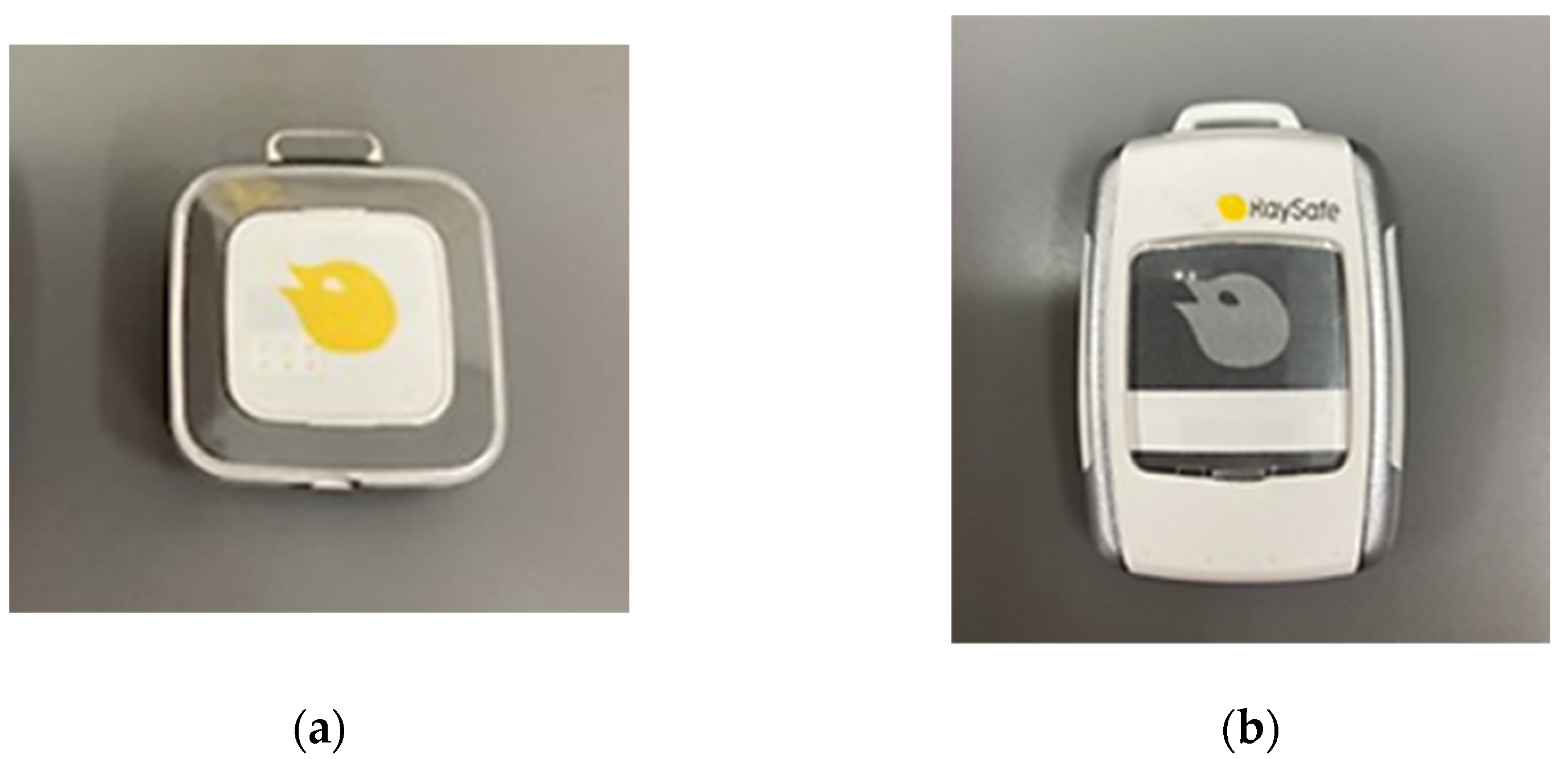
2.1. The i3 Dosimeter
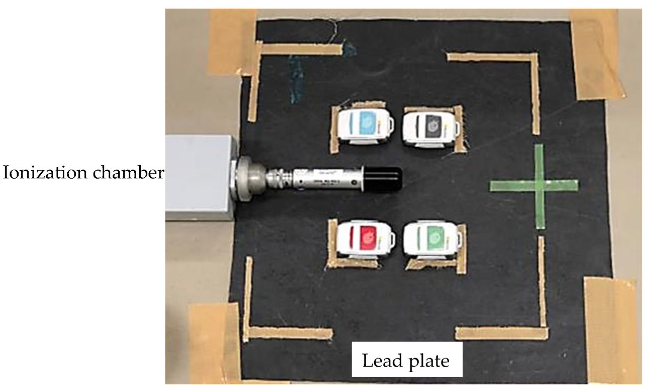
2.2. Fundamental Evaluation
3. Results
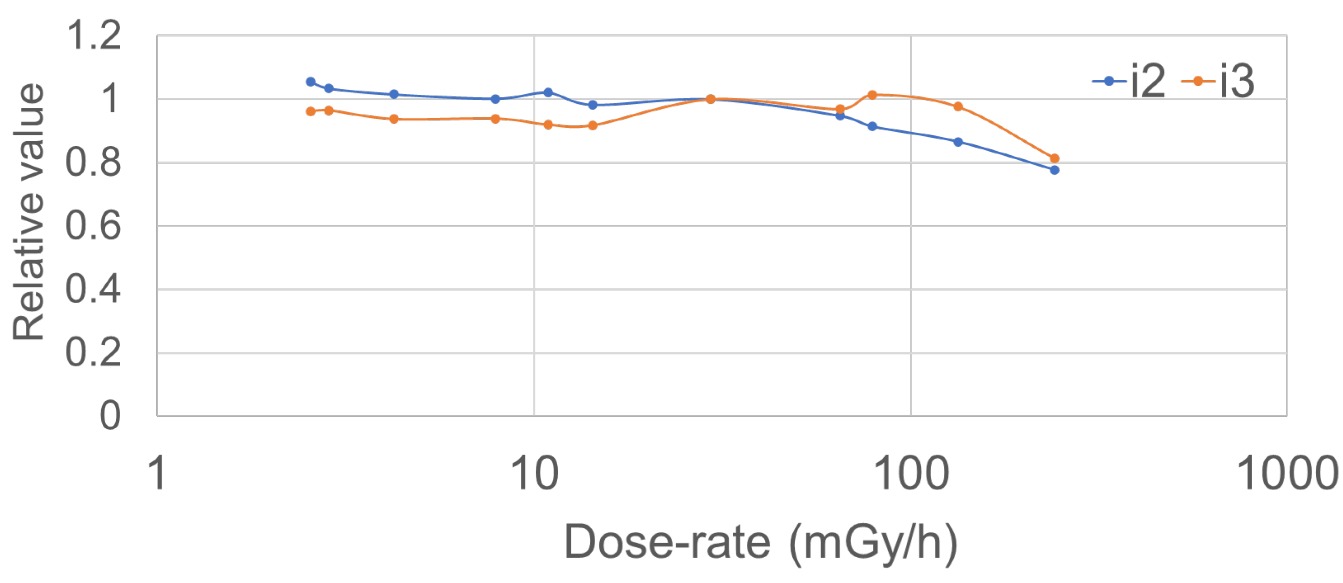
3.1. Fundamental Evaluation
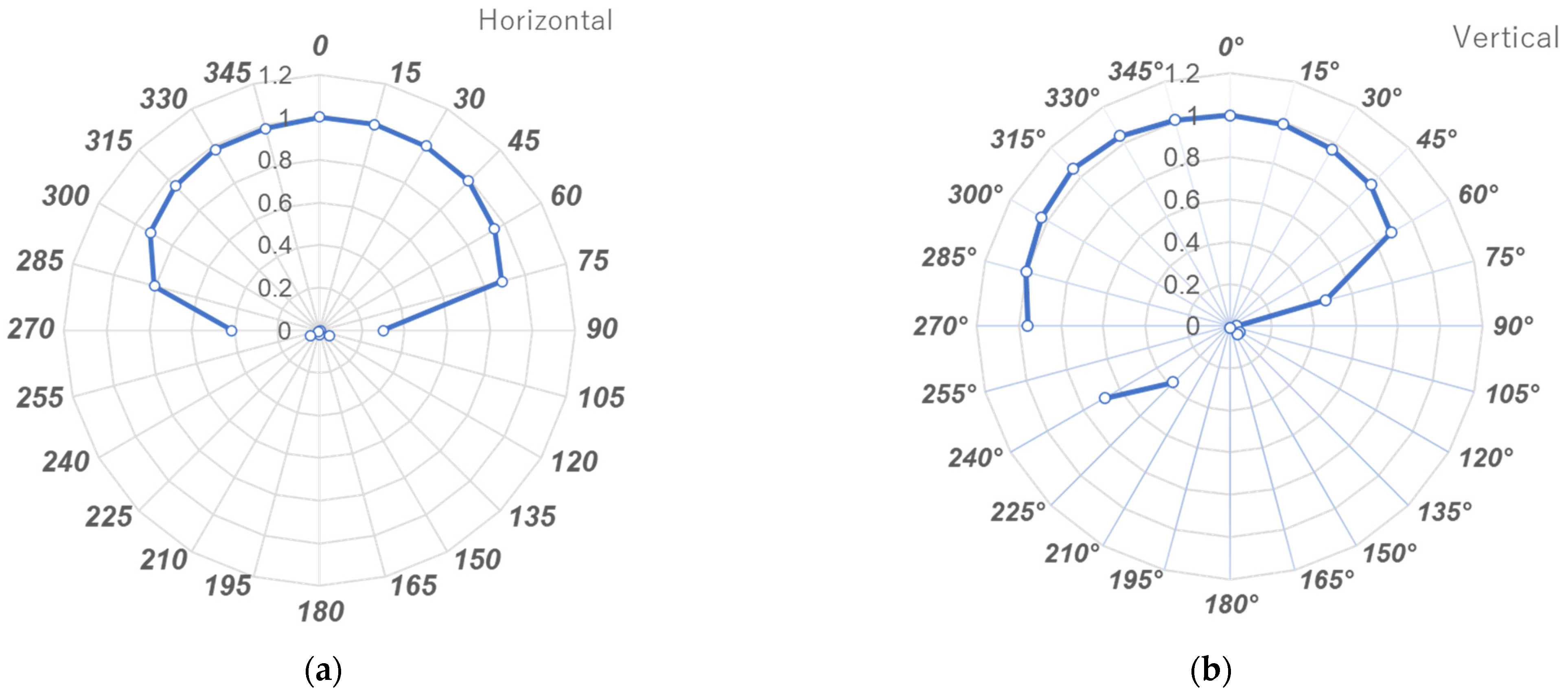
3.2. Angle Dependency
4. Discussion
5. Conclusions
Author Contributions
Funding
Institutional Review Board Statement
Informed Consent Statement
Data Availability Statement
Acknowledgments
Conflicts of Interest
References
- Vano, E.; Escaned, J.; Vano-Galvan, S.; Fernandez, J.M.; Galvan, C. Importance of a patient dosimetry and clinical followup program in the detection of radiodermatitis after long percutaneous coronary interventions. Cardiovasc. Intervent. Radiol. 2013, 36, 330–337. [Google Scholar] [CrossRef] [PubMed]
- Chida, K.; Inaba, Y.; Masuyama, H.; Yanagawa, I.; Mori, I.; Saito, H.; Maruoka, S.; Zuguchi, M. Evaluating the performance of a MOSFET dosimeter at diagnostic X-ray energies for interventional radiology. Radiol. Phys. Technol. 2009, 2, 58–61. [Google Scholar] [CrossRef] [PubMed]
- Matsunaga, Y.; Haba, T.; Kobayashi, M.; Suzuki, S.; Asada, Y.; Chida, K. Novel pregnant model phantoms for measurement of foetal radiation dose in x-ray examinations. J. Radiol. Prot. 2021, 41, N12–N21. [Google Scholar] [CrossRef] [PubMed]
- Inaba, Y.; Chida, K.; Kobayashi, R.; Zuguchi, M. A cross-sectional study of the radiation dose and image quality of X-ray equipment used in IVR. J. Appl. Clin. Med. Phys. 2016, 17, 91–401. [Google Scholar] [CrossRef] [PubMed]
- Chida, K.; Ohno, T.; Kakizaki, S.; Takegawa, M.; Yuuki, H.; Nakada, M.; Takahashi, S.; Zuguchi, M. Radiation dose to the pediatric cardiac catheterization and intervention patient. Am. J. Roentgenol. 2010, 195, 1175–1179. [Google Scholar] [CrossRef]
- Nemoto, M.; Chida, K. Reducing the breast cancer risk and radiation dose of radiography for scoliosis in children: A phantom study. Diagnostics 2020, 10, 753. [Google Scholar] [CrossRef]
- Chida, K.; Saito, H.; Otani, H.; Kohzuki, M.; Takahashi, S.; Yamada, S.; Shirato, K.; Zuguchi, M. Relationship between fluoroscopic time, dose—Area product, body weight, and maximum radiation skin dose in cardiac interventional procedures. Am. J. Roentgenol. 2006, 186, 774–778. [Google Scholar] [CrossRef]
- Inaba, Y.; Nakamura, M.; Zuguchi, M.; Chida, K. Development of novel real-time radiation systems using 4-channel sensors. Sensors 2020, 20, 2741. [Google Scholar] [CrossRef]
- Matsuzaki, S.; Moritake, T.; Morota, K.; Nagamoto, K.; Nakagami, K.; Kuriyama, T.; Kunugita, N. Development and assessment of an educational application for the proper use of ceiling-suspended radiation shielding screens in angiography rooms using augmented reality technology. Eur. J. Radiol. 2021, 143, 109925. [Google Scholar] [CrossRef]
- Sato, T.; Eguchi, Y.; Yamazaki, C.; Hino, T.; Saida, T.; Chida, K. Development of a New Radiation Shield for the Face and Neck of IVR Physicians. Bioengineering 2022, 9, 354. [Google Scholar] [CrossRef]
- International Commission on Radiological Protection (ICRP). Radiological Protection in Cardiology; ICRP Publication 120; Elsevier: Amsterdam, The Netherlands, 2013; Volume 42, Available online: https://journals.sagepub.com/doi/pdf/10.1177/ANIB_42_1 (accessed on 1 November 2022).
- Chida, K.; Kato, M.; Kagaya, Y.; Zuguchi, M.; Saito, H.; Ishibashi, T.; Takahashi, S.; Yamada, S.; Takai, Y. Radiation dose and radiation protection for patients and physicians during interventional procedure. J. Radiat. Res. 2010, 51, 97–105. [Google Scholar] [CrossRef] [Green Version]
- Haga, Y.; Chida, K.; Sota, M.; Kaga, Y.; Abe, M.; Inaba, Y.; Suzuki, M.; Meguro, T.; Zuguchi, M. Hybrid operating room system for the treatment of thoracic and abdominal aortic aneurysms: Evaluation of the radiation dose received by patients. Diagnostics 2020, 10, 846. [Google Scholar] [CrossRef]
- Chida, K. What are useful methods to reduce occupational radiation exposure among radiological medical workers, especially for interventional radiology personnel? Radiol. Phys. Technol. 2022, 15, 101–115. [Google Scholar] [CrossRef]
- Vañó, E.; Gonzalez, L.; Fernández, J.M.; Haskal, Z.J. Eye lens exposure to radiation in interventional suites: Caution is warranted. Radiology 2008, 248, 945–953. [Google Scholar] [CrossRef]
- Kato, M.; Chida, K.; Sato, T.; Oosaka, H.; Tosa, T.; Kadowaki, K. Evaluating the maximum patient radiation dose in cardiac interventional procedures. Radiat. Prot. Dosim. 2011, 143, 69–73. [Google Scholar] [CrossRef]
- Inaba, Y.; Chida, K.; Shirotori, K.; Shimura, H.; Yanagawa, I.; Zuguchi, M.; Takahashi, S. Comparison of the radiation dose in a cardiac IVR X-ray system. Radiat. Prot. Dosim. 2011, 143, 74–80. [Google Scholar] [CrossRef]
- International Commission on Radiological Protection (ICRP). ICRP Statement on Tissue Reactions/Early and Late Effects of Radiation in Normal Tissues and Organs, Threshold Doses for Tissue Reactions in a Radiation Protection Context; ICRP publication 118 Ann. Elsevier: Amsterdam, The Netherlands, 2012; Volume 41, pp. 1–322. Available online: https://www.icrp.org/publication.asp?id=ICRP%20Publication%20118 (accessed on 1 November 2022).
- Chida, K.; Morishima, Y.; Inaba, Y.; Taura, M.; Ebata, A.; Takeda, K.; Shimura, H.; Zuguchi, M. Physician-received scatter radiation with angiography systems used for interventional radiology: Comparison among many X-ray systems. Radiat. Prot. Dosim. 2011, 149, 410–416. [Google Scholar] [CrossRef]
- Zuguchi, M.; Chida, K.; Taura, M.; Inaba, Y.; Ebata, A.; Yamada, S. Usefulness of non-lead aprons in radiation protection for physicians performing interventional procedures. Radiat. Prot. Dosim. 2008, 131, 531–534. [Google Scholar] [CrossRef]
- Ishii, H.; Chida, K.; Satsurai, K.; Haga, Y.; Kaga, Y.; Abe, M.; Inaba, Y.; Zuguchi, M. Occupational eye dose correlation with neck dose and patient-related quantities in interventional cardiology procedures. Radiol. Phys. Technol. 2021, 15, 54–62. [Google Scholar] [CrossRef]
- Chida, K.; Takahashi, T.; Ito, D.; Shimura, H.; Takeda, K.; Zuguchi, M. Clarifying and visualizing sources of staff-received scattered radiation in interventional procedures. Am. J. Roentgenol. 2011, 197, W900–W903. [Google Scholar] [CrossRef]
- International Commission on Radiological Protection (ICRP). Statement on Tissue Reactions; Elsevier: Amsterdam, The Netherlands, 2011; Available online: http://www.icrp.org/docs/ICRP%20Statement%20on%20Tissue%20Reactions.pdf (accessed on 1 November 2022).
- RaySafe i3 Real-Time Radiation Dosimeter|RaySafe. Available online: https://www.raysafe.com/products/real-time-staff-dosimetry/raysafe-i3-real-time-radiation-dosimeter (accessed on 1 November 2022).
- RaySafe i3. Available online: https://www.raysafe.com/sites/default/files/2020-07/RaySafe%20i3%20OSD%20Instructions%20for%20Use%20%28multilingual%29.pdf (accessed on 1 November 2022).
- Inaba, Y.; Chida, K.; Kobayashi, R.; Kaga, Y.; Zuguchi, M. Fundamental study of a real-time occupational dosimetry system for interventional radiology staff. J. Radiol. Prot. 2014, 34, 65–71. [Google Scholar] [CrossRef] [PubMed]
- Coppeta, L.; Pietroiusti, A.; Neri, A.; Spataro, A.; Angelis, E.D.; Perrone, S.; Magrini, A. Risk of radiation-induced lens opacities among surgeons and interventional medical staff. Radiol. Phys. Technol. 2019, 12, 26–29. [Google Scholar] [CrossRef] [PubMed]
- Magee, J.S.; Martin, C.J.; Sandblom, V.; Carter, M.J.; Almén, A.; Cederblad, Å.; Jonasson, P.; Lundh, C. Derivation and application of dose reduction factors for protective eyewear worn in interventional radiology and cardiology. J Radiol Prot. 2014, 34, 811–823. [Google Scholar] [CrossRef] [PubMed]
- Omar, A.; Kadesjö, N.; Palmgren, C.; Marteinsdottir, M.; Segerdahl, T.; Fransson, A. Assessment of the occupational eye lens dose for clinical staff in interventional radiology, cardiology and neuroradiology. J. Radiol. Prot. 2017, 37, 145–159. [Google Scholar] [CrossRef] [PubMed]
- Božović, P.; Ciraj-Bjelac, O.; Petrović, J.S. Occupational eye lens dose estimated using whole—Body dosemeter in interventional cardiology and radiology: A Monte Carlo study, Radiat. Prot. Dosim. 2019, 185, 135–142. [Google Scholar] [CrossRef]
- Kato, M.; Chida, K.; Sato, T.; Oosaka, H.; Tosa, T.; Munehisa, M.; Kadowaki, K. The necessity of follow-up for radiation skin injuries in patients after percutaneous coronary interventions: Radiation skin injuries will often be overlooked clinically. Acta Radiol. 2012, 53, 1040–1044. [Google Scholar] [CrossRef]
- Vañó, E.; González, L.; Beneytez, F.; Moreno, F. Lens injuries induced by occupational exposure in non-optimized interventional radiology laboratories. Br. J. Radiol. 1998, 71, 728–733. [Google Scholar] [CrossRef]
- Vigneux, G.; Pirkkanen, J.; Laframboise, T.; Prescott, H.; Tharmalingam, S.; Thome, C. Radiation-Induced Alterations in Proliferation, Migration, and Adhesion in Lens Epithelial Cells and Implications for Cataract Development. Bioengineering 2022, 9, 29. [Google Scholar] [CrossRef]
- Chida, K.; Kaga, Y.; Haga, Y.; Kataoka, N.; Kumasaka, E.; Meguro, T.; Zuguchi, M. Occupational dose in interventional radiology procedures. Am. J. Roentgenol. 2013, 200, 138–141. [Google Scholar] [CrossRef]
- Chida, K.; Morishima, Y.; Masuyama, H.; Chiba, H.; Katahira, Y.; Inaba, Y.; Mori, I.; Maruoka, S.; Takahashi, S.; Kohzuki, M.; et al. Effect of radiation monitoring method and formula differences on estimated physician dose during percutaneous coronary intervention. Acta Radiol. 2009, 50, 170–173. [Google Scholar] [CrossRef]
- Koenig, A.; Maas, J.; Viniol, S.; Etzel, R.; Fiebich, M.; Thomas, R.; Mahnken, A. Scatter radiation reduction with a radiation-absorbing pad in interventional radiology examinations. Eur. J. Radiol. 2020, 132, 109245. [Google Scholar] [CrossRef]
- Yokoyama, S.; Suzuki, S.; Toyama, H.; Arakawa, S.; Inoue, S.; Kinomura, Y.; Kobayashi, I. Evaluation of eye lens dose of interventional cardiologists, Radiat. Prot. Dosim. 2017, 173, 218–222. [Google Scholar] [CrossRef]
- Morishima, Y.; Chida, K.; Katahira, Y. The effectiveness of additional lead-shielding drape and low pulse rate fluoroscopy in protecting staff from scatter radiation during cardiac resynchronization therapy (CRT). Jpn. J. Radiol. 2019, 37, 95–101. [Google Scholar] [CrossRef]
- Inaba, Y.; Chida, K.; Murabayashi, Y.; Endo, M.; Otomo, K.; Zuguchi, M. An initial investigation of a wireless patient radiation dosimeter for use in interventional radiology. Radiol. Phys. Technol. 2020, 13, 321–326. [Google Scholar] [CrossRef]
- Morishima, Y.; Chida, K.; Meguro, T.; Hirota, M.; Chiba, H.; Fukuda, H. Lens equivalent dose of staff during endoscopic retrograde cholangiopancreatography: Dose comparison using two types of dosemeters. Radiat. Prot. Dosim. 2022, 198, 1368–1376. [Google Scholar] [CrossRef]
- Matsunaga, Y.; Chida, K.; Kondo, Y.; Kobayashi, K.; Kobayashi, M.; Minami, K.; Suzuki, S.; Asada, Y. Diagnostic reference levels and achievable doses for common computed tomography examinations: Results from the Japanese nationwide dose survey. Br. J. Radiol. 2019, 92, 20180290. [Google Scholar] [CrossRef]
- Endo, M.; Haga, Y.; Sota, M.; Tanaka, A.; Otomo, K.; Murabayashi, Y.; Abe, M.; Kaga, Y.; Inaba, Y.; Suzuki, M.; et al. Evaluation of novel X-ray protective eyewear in reducing the eye dose to interventional radiology physicians. J. Radiat. Res. 2021, 62, 414–419. [Google Scholar] [CrossRef]
- Fujibuchi, T. Radiation protection education using virtual reality for the visualisation of scattered distributions during radiological examinations. J Radiol Prot. 2021, 41. [Google Scholar] [CrossRef]
- Kato, M.; Chida, K.; Munehisa, M.; Sato, T.; Inaba, Y.; Suzuki, M.; Zuguchi, M. Non-Lead Protective Aprons for the Protection of Interventional Radiology Physicians from Radiation Exposure in Clinical Settings: An Initial Study. Diagnostics 2021, 11, 1613. [Google Scholar] [CrossRef]
- Matsubara, K. Assessment of Radiation Dose in Medical Imaging and Interventional Radiology Procedures for Patient and Staff Safety. Diagnostics 2021, 11, 1116. [Google Scholar] [CrossRef]
- Chida, K.; Inaba, Y.; Morishima, Y.; Taura, M.; Ebata, A.; Yanagawa, I.; Takeda, K.; Zuguchi, M. Comparison of dose at an interventional reference point between the displayed estimated value and measured value. Radiol. Phys. Technol. 2011, 4, 189–193. [Google Scholar] [CrossRef] [PubMed]
- International Commission on Radiological Protection (ICRP). Avoidance of Radiation Injuries from Medical Interventional Procedures; ICRP Publication 85; Pergamon: Oxford, UK, 2000; Volume 30, Available online: https://journals.sagepub.com/doi/pdf/10.1177/ANIB_30_2 (accessed on 1 November 2022).
- Haga, Y.; Chida, K.; Kaga, Y.; Sota, M.; Meguro, T.; Zuguchi, M. Occupational eye dose in interventional cardiology procedures. Sci. Rep. 2017, 7, 569. [Google Scholar] [CrossRef] [PubMed] [Green Version]
- Kato, M.; Chida, K.; Ishida, T.; Toyoshima, H.; Yoshida, Y.; Yoshioka, S.; Moroi, J.; Kinoshita, T. Occupational radiation exposure of the eye in neurovascular interventional physician. Radiat. Prot. Dosim. 2019, 185, 151–156. [Google Scholar] [CrossRef] [PubMed]
- Haga, Y.; Chida, K.; Kimura, Y.; Yamada, S.; Sota, M.; Abe, M.; Kaga, Y.; Meguro, T.; Zuguchi, M. Radiation eye dose to medical staff during respiratory endoscopy under X-ray fluoroscopy. J. Radiat. Res. 2020, 61, 691–696. [Google Scholar] [CrossRef]
- O’Connor, U.; Walsh, C.; Gallagher, A.; Dowling, A.; Guiney, M.; Ryan, J.M.; McEniff, N.; O’Reilly, G. Occupational radiation dose to eyes from interventional radiology procedures in light of the new eye lens dose limit from the International Commission on Radiological Protection. Br. J. Radiol. 2015, 88, 20140627. [Google Scholar] [CrossRef] [Green Version]
- Ishii, H.; Haga, Y.; Sota, M.; Inaba, Y.; Chida, K. Performance of the DOSIRIS™ eye lens dosimeter. J. Radiol. Prot. 2019, 39, N19–N26. [Google Scholar] [CrossRef]
- Ishii, H.; Chida, K.; Satsurai, K.; Haga, Y.; Kaga, Y.; Abe, M.; Inaba, Y.; Zuguchi, M. A phantom study to determine the optimal placement of eye dosemeters on interventional cardiology staff. Radiat. Prot. Dosim. 2019, 185, 409–413. [Google Scholar] [CrossRef]
- Inaba, Y.; Hitachi, S.; Watanuki, M.; Chida, K. Occupational radiation dose to eye lenses in CT-guided interventions using MDCT-fluoroscopy. Diagnostics 2021, 11, 646. [Google Scholar] [CrossRef]
- Yashima, S.; Chida, K. Awareness of Medical Radiologic Technologists of Ionizing Radiation and Radiation Protection. Int. J. Environ. Res. Public Health 2023, 20, 497. [Google Scholar] [CrossRef]
- Martin, C.J.; Magee, J.S. Assessment of eye and body dose for interventional radiologists, cardiologists, and other interventional staff. J. Radiol. Prot. 2013, 33, 445–460. [Google Scholar] [CrossRef]
- Imai, S.; Akahane, M.; Ogata, Y.; Tanki, N.; Sato, H.; Tameike, K. Occupational eye lens dose in endoscopic retrograde cholangiopancreatography using a dedicated eye lens dosimeter. J. Radiol. Prot. 2021, 41, 579–589. [Google Scholar] [CrossRef]
- Inaba, Y.; Hitachi, S.; Watanuki, M.; Chida, K. Radiation Eye Dose for Physicians in CT Fluoroscopy-Guided Biopsy. Tomography 2022, 8, 438–446. [Google Scholar] [CrossRef]
- Inaba, Y.; Nakamura, M.; Chida, K.; Zuguchi, M. Effectiveness of a novel real-time dosimeter in interventional radiology: A comparison of new and old radiation sensors. Radiol. Phys. Technol. 2018, 11, 445–450. [Google Scholar] [CrossRef]
- Chida, K.; Kato, M.; Inaba, Y.; Kobayashi, R.; Nakamura, M.; Abe, Y.; Zuguchi, M. Real-time patient radiation dosimeter for use in interventional radiology. Phys. Med. 2016, 32, 1475–1478. [Google Scholar] [CrossRef]
- Haskal, Z.J.; Worgul, B.V. 2004 Interventional radiology carries occupational risk for cataracts. RSNA News. 2004, 14, 5–6. [Google Scholar]
- Ainsbury, E.A.; Bouffler, S.D.; Dörr, W.; Graw, J.; Muirhead, C.R.; Edwards, A.A.; Cooper, J. Radiation cataractogenesis: A review of recent studies. Radiat. Res. 2009, 172, 1–9. [Google Scholar] [CrossRef]
- Nakamura, M.; Chida, K.; Zuguchi, M. Novel Dosimeter Using a Nontoxic Phosphor for Real-Time Monitoring of Patient Radiation Dose in Interventional Radiology. AJR Am. J. Roentgenol. 2015, 205, W202–W206. [Google Scholar] [CrossRef]
- Nakamura, M.; Chida, K.; Zuguchi, M. Red emission phosphor for real-time skin dosimeter for fluoroscopy and interventional radiology. Med. Phys. 2014, 41, 101913. [Google Scholar] [CrossRef]
- Diagnostic Reference Level in Japan (2020 Version). Available online: http://www.radher.jp/J-RIME/report/JapanDRL2020_jp.pdf (accessed on 1 November 2022).


| Tube Voltage (kV) | 50 | 60 | 70 | 80 | 90 | 100 | 110 |
|---|---|---|---|---|---|---|---|
| Half value layer (mmAl) | 2.0 | 2.4 | 2.8 | 3.2 | 3.7 | 4.15 | 4.7 |
| Reproducibility (%) | Batch Uniformity (%) | |
|---|---|---|
| condition (1) | 2.099 (range 1.380–3.192) | 3.24 |
| condition (2) | 2.216 (range 1.934–2.398) | 3.43 |
| condition (3) | 4.847 (range 2.291–6.913) | 8.14 |
| Tube Voltage | 60 kV | 80 kV | 100 kV | ||||||
|---|---|---|---|---|---|---|---|---|---|
| Fluoroscopy Duration | 3 s | 10 s | 60 s | 3 s | 10 s | 60 s | 3 s | 10 s | 60 s |
| i3 measurements (μSv/h) | 57.5 | 30.5 | 19.5 | 59.6 | 34.5 | 21.3 | 48.4 | 27.3 | 16.6 |
| i2 measurements (μSv/h) | 185.7 | 46.3 | 41.3 | 101.3 | 31.2 | 35.2 | 99.8 | 39.8 | 22.2 |
Disclaimer/Publisher’s Note: The statements, opinions and data contained in all publications are solely those of the individual author(s) and contributor(s) and not of MDPI and/or the editor(s). MDPI and/or the editor(s) disclaim responsibility for any injury to people or property resulting from any ideas, methods, instructions or products referred to in the content. |
© 2023 by the authors. Licensee MDPI, Basel, Switzerland. This article is an open access article distributed under the terms and conditions of the Creative Commons Attribution (CC BY) license (https://creativecommons.org/licenses/by/4.0/).
Share and Cite
Hattori, K.; Inaba, Y.; Kato, T.; Fujisawa, M.; Yasuno, H.; Yamada, A.; Haga, Y.; Suzuki, M.; Zuguchi, M.; Chida, K. Evaluation of a New Real-Time Dosimeter Sensor for Interventional Radiology Staff. Sensors 2023, 23, 512. https://doi.org/10.3390/s23010512
Hattori K, Inaba Y, Kato T, Fujisawa M, Yasuno H, Yamada A, Haga Y, Suzuki M, Zuguchi M, Chida K. Evaluation of a New Real-Time Dosimeter Sensor for Interventional Radiology Staff. Sensors. 2023; 23(1):512. https://doi.org/10.3390/s23010512
Chicago/Turabian StyleHattori, Kenshin, Yohei Inaba, Toshiki Kato, Masaki Fujisawa, Hikaru Yasuno, Ayumi Yamada, Yoshihiro Haga, Masatoshi Suzuki, Masayuki Zuguchi, and Koichi Chida. 2023. "Evaluation of a New Real-Time Dosimeter Sensor for Interventional Radiology Staff" Sensors 23, no. 1: 512. https://doi.org/10.3390/s23010512