
An Efficient Procedure for Bonding Piezoelectric Transducers to Thermoplastic Composite Structures for SHM Application and Its Durability in Aeronautical Environmental Conditions

Abstract
:1. Introduction
- Obtaining controllable and reliably repeatable bonding quality by using TPFs rather than liquid two-part epoxy adhesives;
- Using TP adhesive films in place of epoxy adhesives, which are irreparable, are often messy, and have long curing cycles;
- Easy replacement of faulty PCTs without damaging or disturbing the host structure in any form;
- Demonstrating the integrity, durability, and reliability of this new bonding procedure in AOEC in accordance to the aeronautical standard DO-160 and comparing the results with a reference epoxy adhesive.
2. Experimental Methods
2.1. Materials
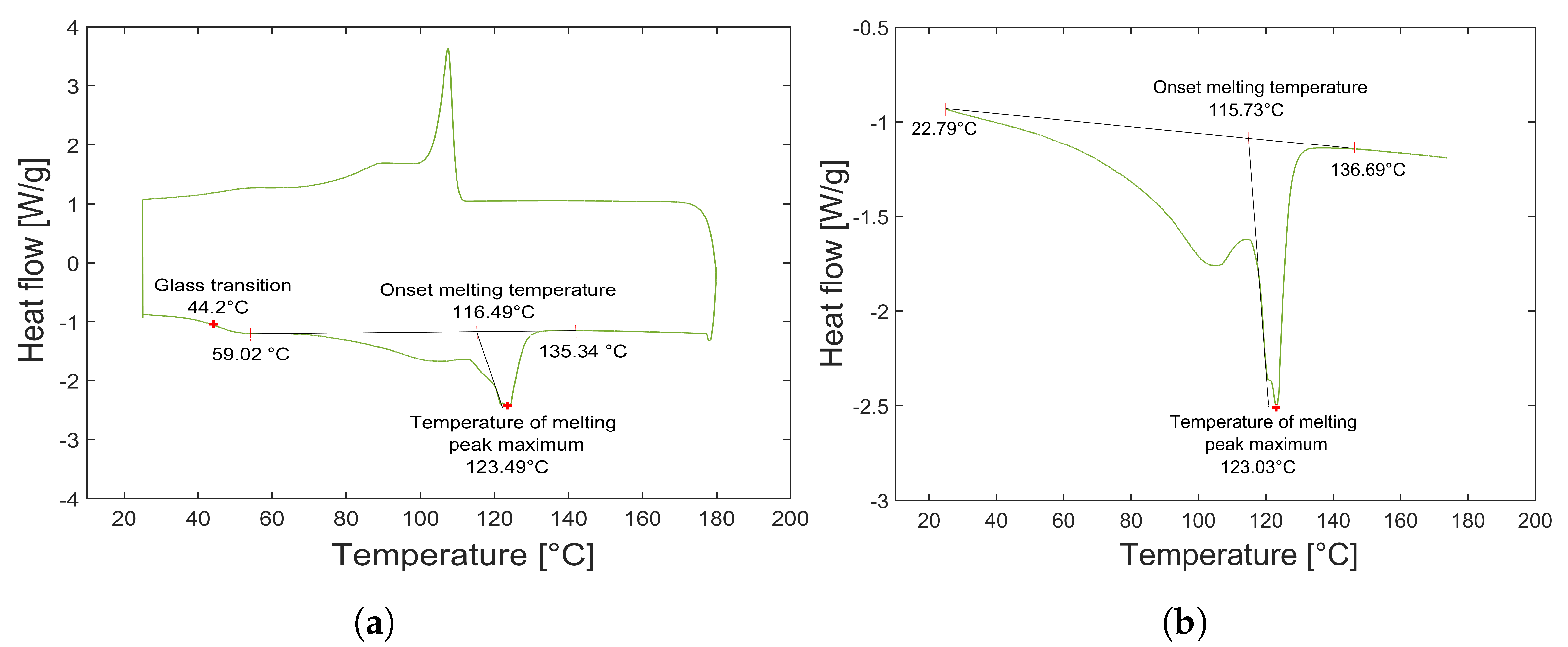
- Melting temperature () ≤ 150 °C: The of the TPFs should be less than the maximum allowable temperature of the PCTs under consideration and should not exceed the glass transition temperature of PEEK.
- Deflection temperature ≥ 70 °C: The deflection temperature of the TPFs should be greater than the service temperature of the host structure (Aircraft structure) or the higher operating temperature as defined by the DO-160 standard for internal electronic components, i.e., 70 °C.
- Good bonding strength: The adhesive bond line should be able to resist the strains and should not fail during the normal loading conditions. Semi-crystalline TPFs will be preferred because of their better mechanical performance and chemical resistance and predictable behavior as compared to the amorphous polymer films [31].
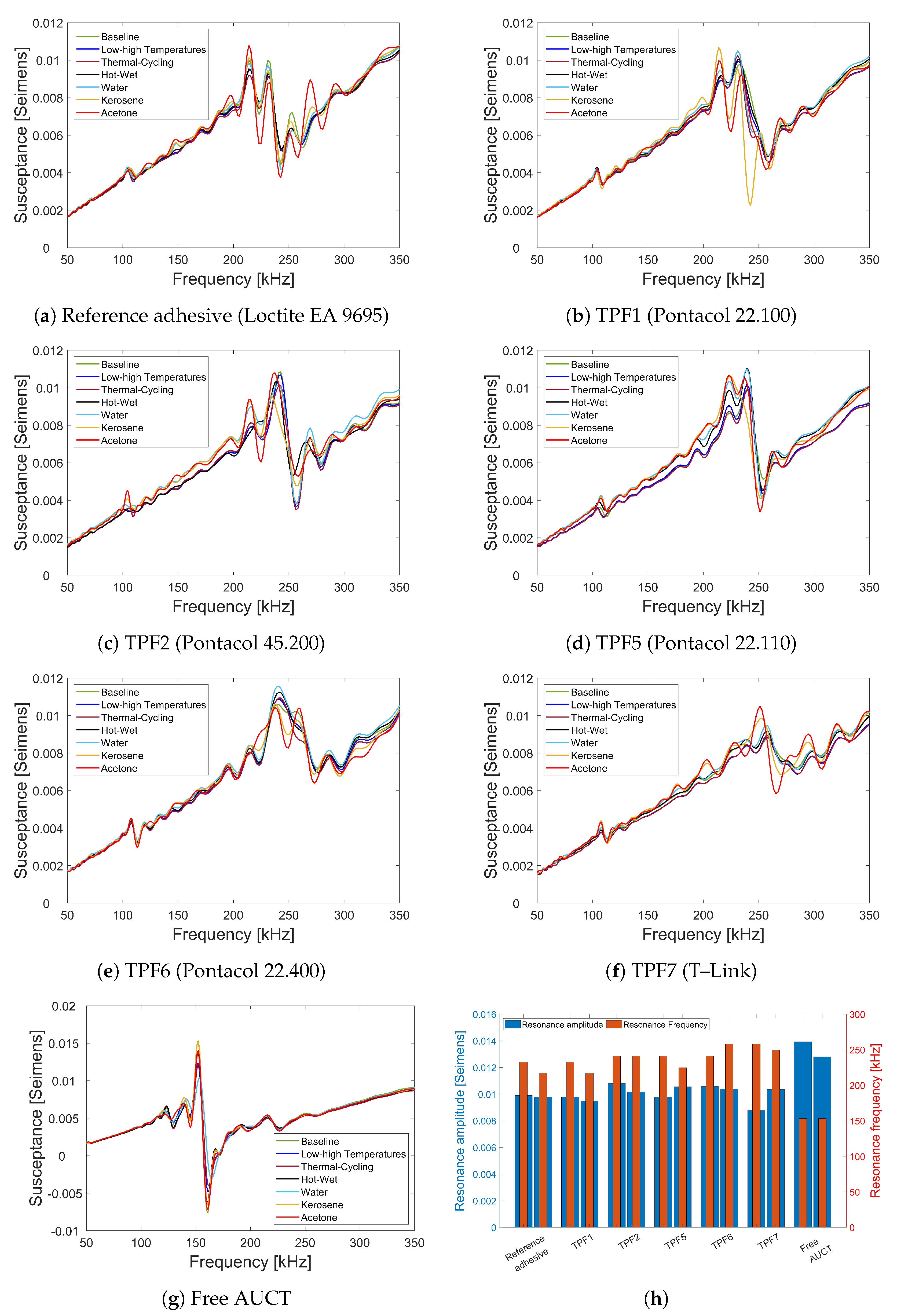
- The slope of the SS curve obtaining through linear fitting;
- The change in the resonance characteristics of the SS, i.e., the amplitude and the frequency of the first natural frequency. The first resonant peak is used, because the guided waves are generated using this frequency range for the AUCTs under consideration.
2.2. Thermal Analysis of Thermoplastic Films
2.3. Transducer Bonding and Reparability
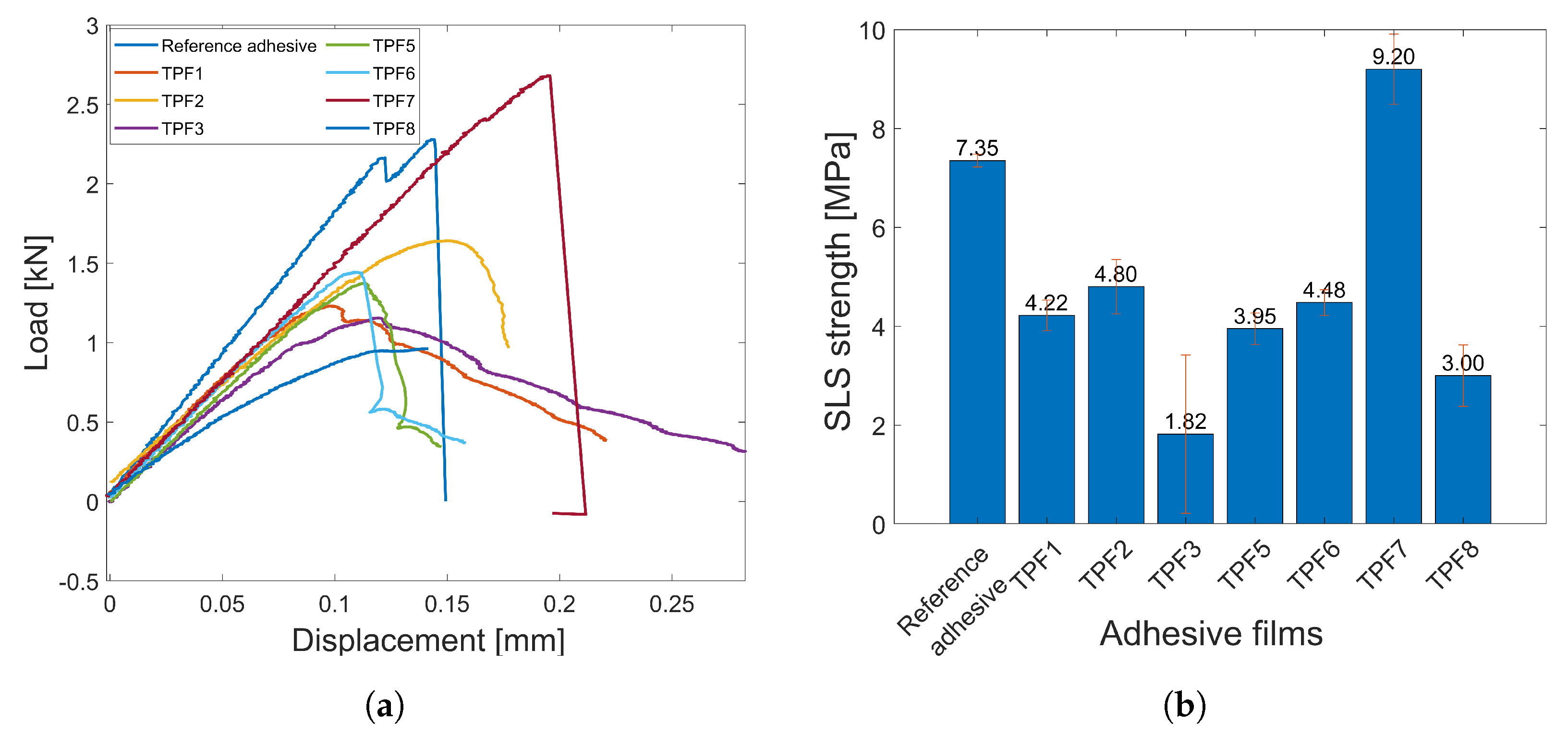
2.4. Adhesive Bonding Quality
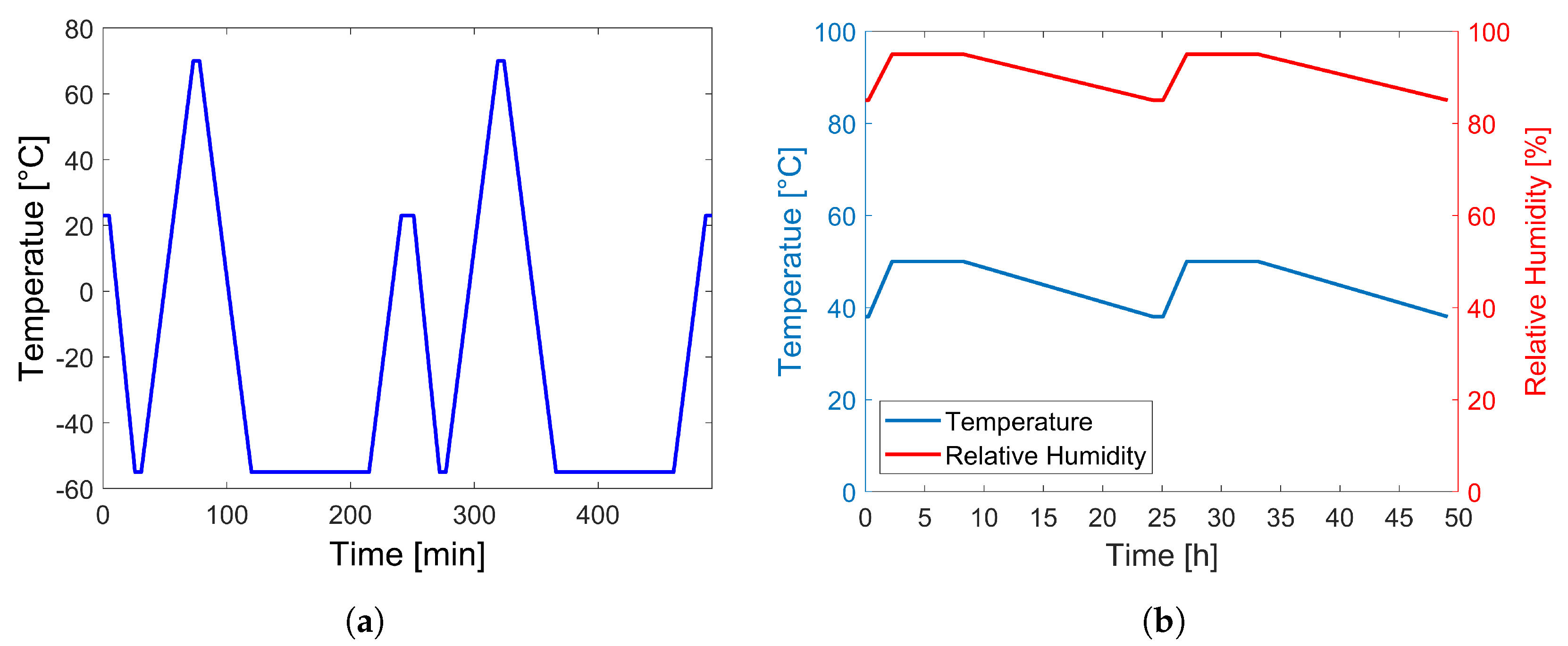
2.5. Aircraft Operational Environmental Condition Tests
3. Results and Discussion
3.1. Adhesive Characterization
3.1.1. Thermal Analysis
3.1.2. Reparability and Bonding
3.2. Sensor Defects
3.3. Durability and Integrity
4. Conclusions and Outlook
Author Contributions
Funding
Data Availability Statement
Acknowledgments
Conflicts of Interest
References
- Rajak, D.K.; Pagar, D.D.; Kumar, R.; Pruncu, C.I. Recent progress of reinforcement materials: A comprehensive overview of composite materials. J. Mater. Res. Technol. 2019, 8, 6354–6374. [Google Scholar] [CrossRef]
- Cantwell, W.J.; Morton, J. The impact resistance of composite materials—A review. Composites 1991, 22, 347–362. [Google Scholar] [CrossRef]
- Qing, X.; Li, W.; Wang, Y.; Sun, H. Piezoelectric Transducer-Based Structural Health Monitoring for Aircraft Applications. Sensors 2019, 19, 545. [Google Scholar] [CrossRef] [PubMed]
- Lambinet, F.; Khodaei, Z.S. Development of Hybrid Piezoelectric-Fibre Optic Composite Patch Repair Solutions. Sensors 2021, 21, 5131. [Google Scholar] [CrossRef]
- Güemes, A.; Fernandez-Lopez, A.; Pozo, A.R.; Sierra-Pérez, J. Structural Health Monitoring for Advanced Composite Structures: A Review. J. Compos. Sci. 2020, 4, 13. [Google Scholar] [CrossRef]
- Schmidt, D. Modenselektive Übertragung von Lambwellen in Faserverbundstrukturen. Ph.D. Thesis, Technischen Universität Carolo-Wilhelmina, Braunschweig, Germany, 2014. [Google Scholar]
- Chang, F.K. Structural Health Monitoring 2013: A Roadmap to Intelligent Structures: Proceedings of the 9th International Workshop on Structural Health Monitoring, 9th ed.; DEStech Publications: Lancaster, PA, USA, 2013. [Google Scholar]
- Yue, N. Stochastic Analysis of Guided Wave Structural Health Monitoring for Aeronautical Composites. Ph.D. Thesis, Imperial College London, London, UK, 2019. [Google Scholar]
- Yue, N.; Khodaei, Z.S.; Aliabadi, M.H. An Innovative Secondary Bonding of Sensors to Composite Structures for SHM Application. Key Eng. Mater. 2018, 774, 516–522. [Google Scholar] [CrossRef]
- Moix-Bonet, M.; Buethe, I.; Bach, M.; Fritzen, C.P.; Wierach, P. Durability of Co-bonded Piezoelectric Transducers. Proc. Technol. 2014, 15, 638–647. [Google Scholar] [CrossRef]
- Selzer, R.; Friedrich, K. Mechanical properties and failure behaviour of carbon fibre-reinforced polymer composites under the influence of moisture. Compos. Part A Appl. Sci. 1997, 28, 595–604. [Google Scholar] [CrossRef]
- Ma, C.C.M.; Yur, S.W. Environmental Effect on the Water Absorption and Mechanical Properties of Carbon Fiber Reinforced PPS and PEEK Composites. J. Thermoplast. Compos. Mater. 1989, 2, 281–292. [Google Scholar] [CrossRef]
- Gall, M.; Thielicke, B.; Schmidt, I. Integrity of piezoceramic patch transducers under cyclic loading at different temperatures. Smart Mater. Struct. 2009, 18, 104009. [Google Scholar] [CrossRef]
- Blackshire, J.L.; Giurgiutiu, V.; Cooney, A.; Doane, J. Characterization of sensor performance and durability for structural health monitoring systems. In Proceedings of the Advanced Sensor Technologies for Nondestructive Evaluation and Structural Health Monitoring. International Society for Optics and Photonics, San Diego, CA, USA, 6–10 March 2005; Volume 5770, pp. 66–75. [Google Scholar] [CrossRef]
- Mueller, I.; Fritzen, C.P. Inspection of Piezoceramic Transducers Used for Structural Health Monitoring. Materials 2017, 10, 71. [Google Scholar] [CrossRef]
- Ha, S.; Lonkar, K.; Mittal, A.; Chang, F.K. Adhesive Layer Effects on PZT-induced Lamb Waves at Elevated Temperatures. Struct. Health Monit. 2010, 9, 247–256. [Google Scholar] [CrossRef]
- Buethe, I.; Moix-Bonet, M.; Wierach, P.; Fritzen, C.P. Check of Piezoelectric Transducers Using the Electro-Mechanical Impedance. In Proceedings of the 7th European Workshop on Structural Health Monitoring, Nantes, France, 8–11 July 2014. [Google Scholar]
- Meisner, C.; Stolz, C.; Hofmann, F. Durability Assessment of PZT-Transducers for Guided Wave Based SHM Systems Using tensile static and fatigue tests. In Proceedings of the 7th International Symposium on NDT in Aerospace, Bremen, Germany, 16–18 November 2015. [Google Scholar]
- Habas, D.; Schmidt, D.; Dobmann, N.; Papadopoulos, M. Manufacturing of CFRP Panels with Integrated Sensor Network and Contacting of the Network. In Proceedings of the Smart Intelligent Aircraft Structures (SARISTU); Springer: Cham, Switzerland, 2016; pp. 605–615. [Google Scholar]
- Gong, P.; Hay, T.R.; Greve, D.W.; Junker, W.R.; Oppenheim, I.J. Compensating temperature-induced ultrasonic phase and amplitude changes. In Proceedings of the Sensors and Smart Structures Technologies for Civil, Mechanical, and Aerospace Systems 2016, Las Vegas, NV, USA, 20–24 March 2016; Volume 9803, p. 98033K. [Google Scholar] [CrossRef]
- Feng, T.; Aliabadi, M.H. Smart Patch for Structural Health Monitoring of Composite Repair. Appl. Sci. 2022, 12, 4916. [Google Scholar] [CrossRef]
- Ochôa, P.; Fernandez Villegas, I.; Groves, R.M.; Benedictus, R. Experimental assessment of the influence of welding process parameters on Lamb wave transmission across ultrasonically welded thermoplastic composite joints. Mech. Syst. Signal Process. 2018, 99, 197–218. [Google Scholar] [CrossRef]
- Eckstein, B.; Bach, M.; Bockenheimer, C.; Cheung, C.; Chung, H.; Zhang, D.; Li, F. Large scale monitoring of CFRP structures by acousto-ultrasonics-a flight test experience. In Proceedings of the 9th International Workshop on Structural Health Monitoring 2013, Stanford, CA, USA, 10–12 September 2013; pp. 528–535. [Google Scholar]
- Marzani, A.; Testoni, N.; Marchi, L.D.; Messina, M.; Monaco, E.; Apicella, A. An open database for benchmarking guided waves structural health monitoring algorithms on a composite full-scale outer wing demonstrator. Struct. Health Monit. 2019, 19, 1524–1541. [Google Scholar] [CrossRef]
- Thielicke, B.; Gesang, T.; Wierach, P. Reliability of piezoceramic patch sensors under cyclic mechanical loading. Smart Mater. Struct. 2003, 12, 993–996. [Google Scholar] [CrossRef]
- Salmanpour, M.S.; Khodaei, Z.S.; Aliabadi, M.H. Airborne Transducer Integrity under Operational Environment for Structural Health Monitoring. Sensors 2016, 16, 2110. [Google Scholar] [CrossRef]
- Wierach, P. Electromechanical Functional Module and Associated Process. U.S. Patent 6,930,439 B2, 16 August 2005. [Google Scholar]
- Lin, M.; Qing, X.; Kumar, A.; Beard, S.J. SMART Layer and SMART Suitcase for structural health monitoring applications. In Proceedings of the Smart Structures and Materials 2001: Industrial and Commercial Applications of Smart Structures Technologies, Newport Beach, CA, USA, 4–8 March 2001; Volume 4332, pp. 98–106. [Google Scholar] [CrossRef]
- Goossens, S. Barely visible impact damage detection in aerospace-grade carbon fibre reinforced polymer components with optical fibre sensors. Ph.D. Thesis, Vrije Universiteit Brussel, Brussels, Belgium, 2021. [Google Scholar] [CrossRef]
- Miguel Giraldo, C. Desarrollo de Sensores de Fibra óptica para su Aplicación a la Monitorización de la Integridad Estructural en Estructuras Aeronáuticas de Material Compuesto. Ph.D. Thesis, Universidad Politécnica de Madrid, Madrid, Spain, 2018. [Google Scholar] [CrossRef]
- Djukic, S.; Bocahut, A.; Bikard, J.; Long, D.R. Mechanical properties of amorphous and semi-crystalline semi-aromatic polyamides. Heliyon 2020, 6, E03857. [Google Scholar] [CrossRef]
- Schmidt, D.; Kolbe, A.; Kaps, R.; Wierach, P.; Linke, S.; Steeger, S.; von Dungern, F.; Tauchner, J.; Breu, C.; Newman, B. Development of a Door Surround Structure with Integrated Structural Health Monitoring System. In Proceedings of the Smart Intelligent Aircraft Structures (SARISTU); Springer: Cham, Switzerland, 2016; pp. 935–945. [Google Scholar]
- Liang, C.; Sun, F.P.; Rogers, C.A. Coupled Electro-Mechanical Analysis of Adaptive Material Systems—Determination of the Actuator Power Consumption and System Energy Transfer. J. Intell. Mater. Syst. Struct. 1994, 5, 12–20. [Google Scholar] [CrossRef]
- Park, G.; Farrar, C.R.; di Scalea, F.; Coccia, S. Performance assessment and validation of piezoelectric active-sensors in structural health monitoring. Smart Mater. Struct. 2006, 15, 1673. [Google Scholar] [CrossRef]
- Jiang, X.; Zhang, X.; Tang, T.; Zhang, Y. Electromechanical impedance based self-diagnosis of piezoelectric smart structure using principal component analysis and LibSVM. Sci. Rep. 2021, 11, 11345. [Google Scholar] [CrossRef] [PubMed]
- Memmolo, V.; Park, Y.J.; Lilov, M.; Monaco, E.; Ricci, F. Preliminary acousto-ultrasonic investigation for multi-parameter transducer self-diagnostic system in composites. Compos. Struct. 2018, 202, 1229–1238. [Google Scholar] [CrossRef]
- Lin, Y.; Bilotti, E.; Bastiaansen, C.W.; Peijs, T. Transparent semi-crystalline polymeric materials and their nanocomposites: A review. Polym. Eng. Sci. 2020, 60, 2351–2376. [Google Scholar] [CrossRef]


| Propery/Parameter | Epoxy (Thermoset Adhesives) | TP Adhesives |
|---|---|---|
| Storage | Refrigeration maybe required | No refrigeration required, can be stored at room temperature |
| Shelf life at room temperature | Short | Long |
| Cycle times | Longer | Shorter |
| Reparability | Difficult | Yes |
| Weldability | No | Yes |
| Adhesive Film | Material | Supplier |
|---|---|---|
| 22.100 (TPF1) | Polyolefin (POF) | Pontacol |
| 45.200 (TPF2) | POF/Copolyamide (Multi-layer) | |
| 45.350 (TPF3) | POF/ Polyurethane (PUT) (Multi-layer) | |
| 46.302 (TPF4) | PUT | |
| 22.110 (TPF5) | Low-density polyethylene | |
| 22.400 (TPF6) | High-density polyethylene | |
| T-Link (TPF7) | Unknown | L&L Products |
| PAF-130 (TPF8) | Polyester | AdhesiveInc. |
| NAF-605 (TPF9) | Polyamide | |
| UAF-438 (TPF10) | PUT | |
| UAF-472 (TPF11) | ||
| EXF-951 (TPF12) | ||
| UAF-410 (TPF13) |
| Integrity Test | Standard | Parameters | Equipment |
|---|---|---|---|
| Temperature | RTCA DO-160E-4.5.2 RTCA DO-160E-4.5.4 | Operating high temperature at 70 °C for 2 h Operating low temperature at −55 °C for 2 h | |
| Thermal cycling | RTCA DO-160E-5.3.1 | Shock from −55 °C to 70 °C in 25 min. | Dycometal CCK-70/80 Climate Chamber |
| Hot-Wet | RTCA DO-160E-6.3.1 | 50 °C to 38 °C (5 °C/min) RH 95% to 85% for 48 h | |
| Fluid susceptibility | RTCA DO-160E-11.4.2 | Immersed in water for 168 h at 70 °C, Kerosene for 24 h at 40 °C and Acetone for 24 h at Room temperature 24 °C. |
| Adhesive Film | Average [°C] | Reparability | Average SLS [MPa] |
|---|---|---|---|
| Reference adhesive | - | No | 7.35 |
| TPF1 | 123.0 | Yes | 4.22 |
| TPF2 | 122.4 | Yes | 4.80 |
| TPF3 | 122.4 | Yes | 1.82 |
| TPF4 | - | No | Not tested |
| TPF5 | 116.2 | Yes | 3.95 |
| TPF6 | 127.9 | Yes | 4.48 |
| TPF7 | - | Yes | 9.20 |
| TPF8 | 121.9 | Yes | 3.00 |
| TPF9 | 75.5 | Not tested | Not tested |
| TPF10 | 49.2 | ||
| TPF11 | 48.4 | ||
| TPF12 | - | ||
| TPF13 | 47.0 |
Disclaimer/Publisher’s Note: The statements, opinions and data contained in all publications are solely those of the individual author(s) and contributor(s) and not of MDPI and/or the editor(s). MDPI and/or the editor(s) disclaim responsibility for any injury to people or property resulting from any ideas, methods, instructions or products referred to in the content. |
© 2023 by the authors. Licensee MDPI, Basel, Switzerland. This article is an open access article distributed under the terms and conditions of the Creative Commons Attribution (CC BY) license (https://creativecommons.org/licenses/by/4.0/).
Share and Cite
Sofi, T.; Gude, M.R.; Wierach, P.; Martin, I.; Lorenzo, E. An Efficient Procedure for Bonding Piezoelectric Transducers to Thermoplastic Composite Structures for SHM Application and Its Durability in Aeronautical Environmental Conditions. Sensors 2023, 23, 4784. https://doi.org/10.3390/s23104784
Sofi T, Gude MR, Wierach P, Martin I, Lorenzo E. An Efficient Procedure for Bonding Piezoelectric Transducers to Thermoplastic Composite Structures for SHM Application and Its Durability in Aeronautical Environmental Conditions. Sensors. 2023; 23(10):4784. https://doi.org/10.3390/s23104784
Chicago/Turabian StyleSofi, Tasdeeq, Maria R. Gude, Peter Wierach, Isabel Martin, and Eduardo Lorenzo. 2023. "An Efficient Procedure for Bonding Piezoelectric Transducers to Thermoplastic Composite Structures for SHM Application and Its Durability in Aeronautical Environmental Conditions" Sensors 23, no. 10: 4784. https://doi.org/10.3390/s23104784