
Advancements in Neighboring-Based Energy-Efficient Routing Protocol (NBEER) for Underwater Wireless Sensor Networks
 ,
,  ,
,  , , and
Abstract
:1. Introduction
- Energy consumption and latency reduction: The proposed routing technique introduces a novel routing scheme aimed at minimizing energy consumption and addressing latency issues. This is achieved through the utilization of neighbor node data cooperation, enabling efficient data transfer to the base station.
- Neighbor node cooperation: The proposed method incorporates neighbor node cooperation to optimize energy consumption. By selecting neighbor nodes with high residual energy as neighbor head nodes (NHNs), data can be efficiently transmitted to the sink node located on the water surface.
- Enhancing data reliability: Recognizing that direct data transmission does not guarantee reliability, the proposed approach employs neighbor node cooperative data forwarding. This technique effectively reduces end-to-end delay and enhances the network’s overall lifetime.
- Performance evaluation: The research evaluates the performance of the routing scheme using the MATLAB simulation tool. The results demonstrate improvements in energy consumption, end-to-end delay, packet delivery ratio (PDR), transmission loss, and the number of packets received.
2. Literature Review
3. Methodology
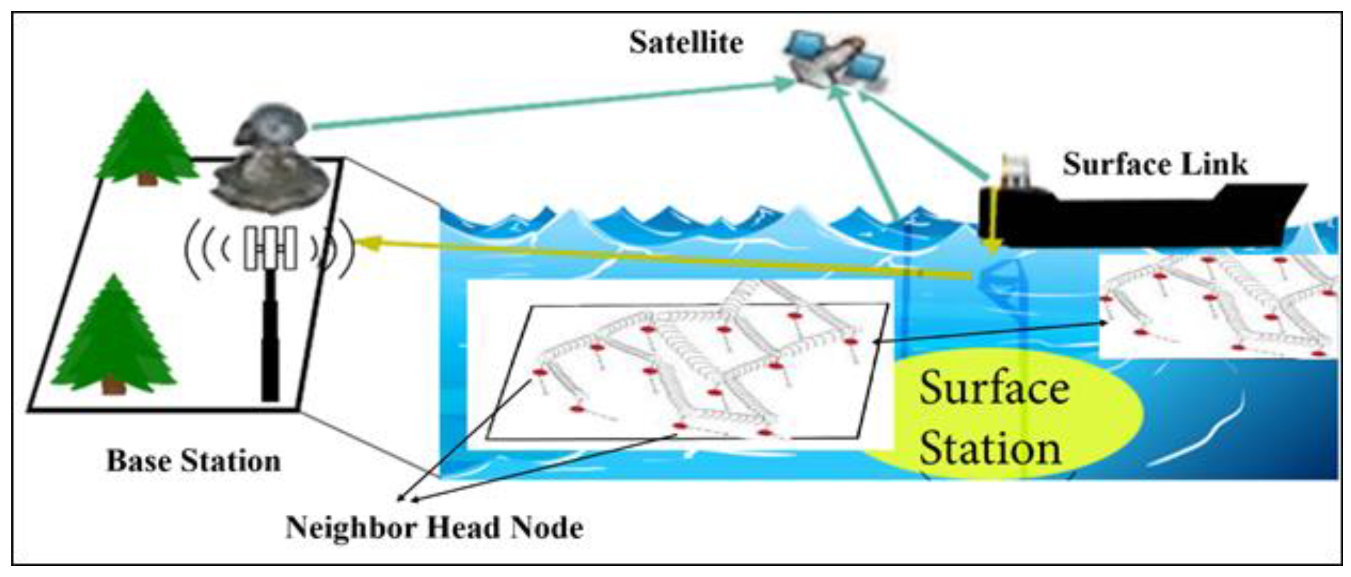
3.1. System Model
3.1.1. Node Deployment
3.1.2. Data Processing
3.1.3. Node Discovery
3.1.4. Route Analysis
3.1.5. Depth Communication
3.1.6. Neighboring Node Identification (NNI)
3.1.7. Choosing the Neighbor Head Node
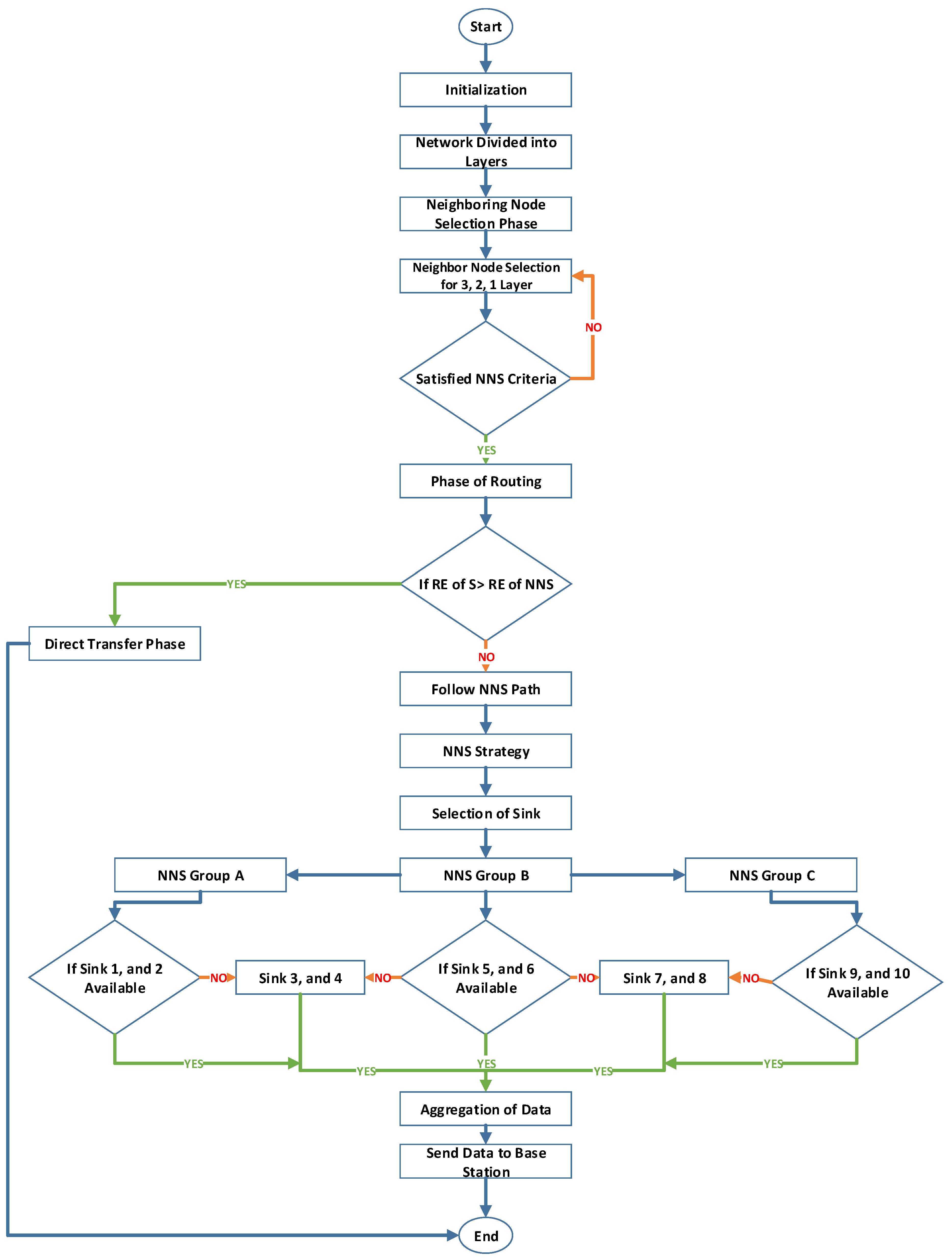
3.1.8. Neighbor Head Node Selection and Path Determination Phase
3.1.9. Neighbor Head Node Methodology
3.1.10. Integration Approach
| Algorithm 1: For the proposed NBEER routing protocol for UWSN |
|
4. Experiments
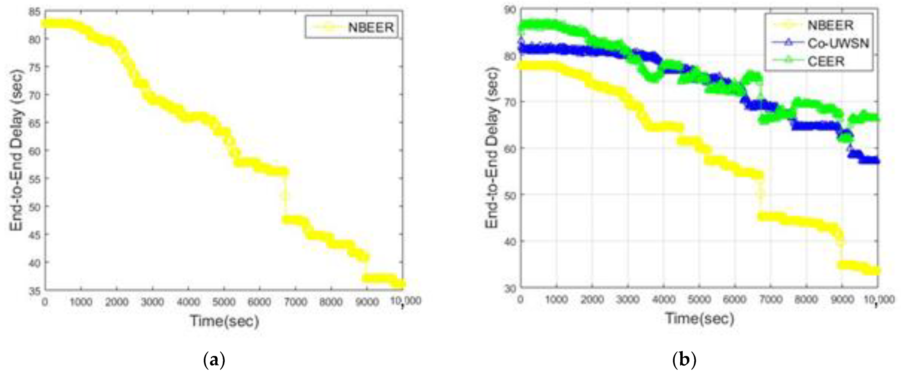
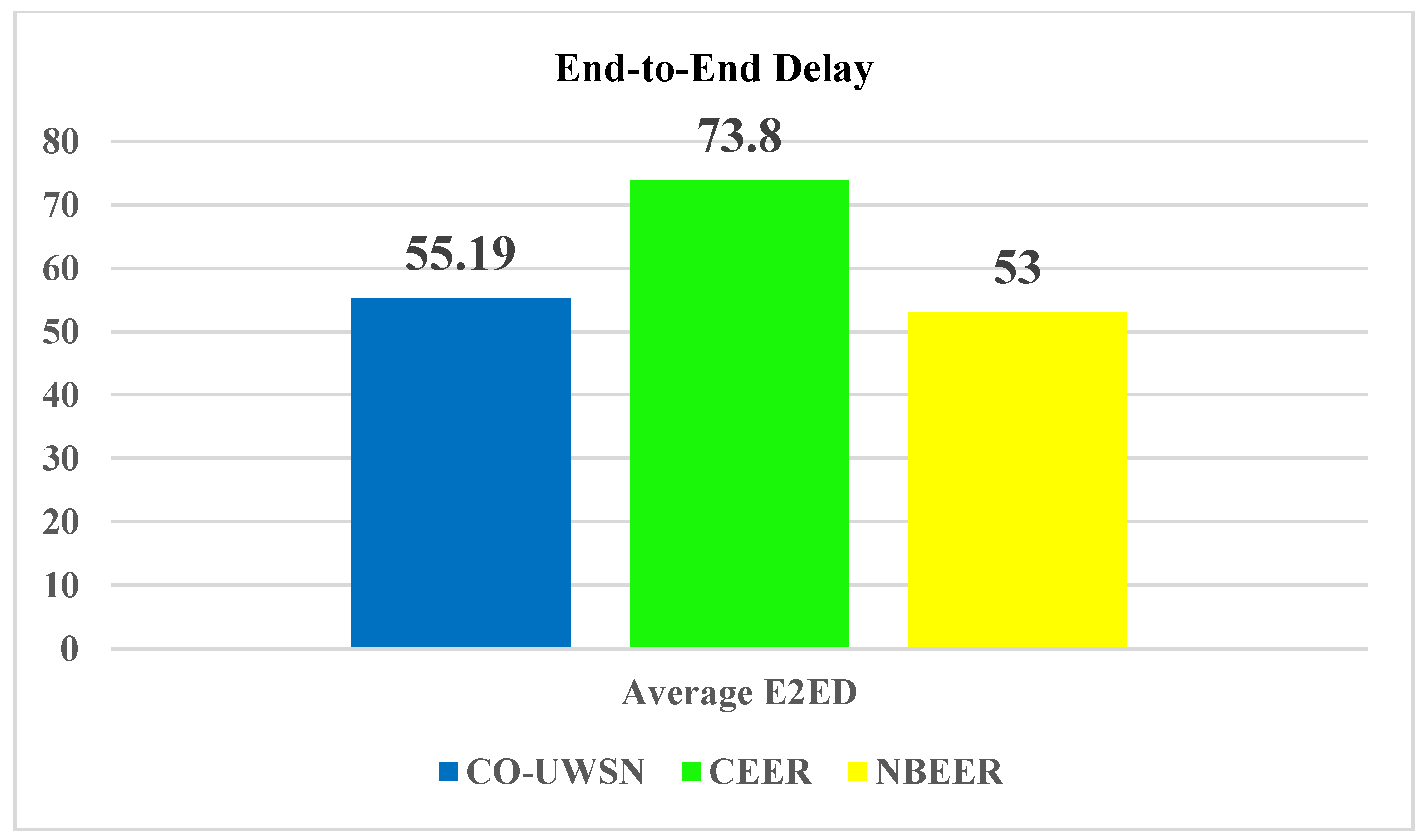
4.1. End-to-End Delay
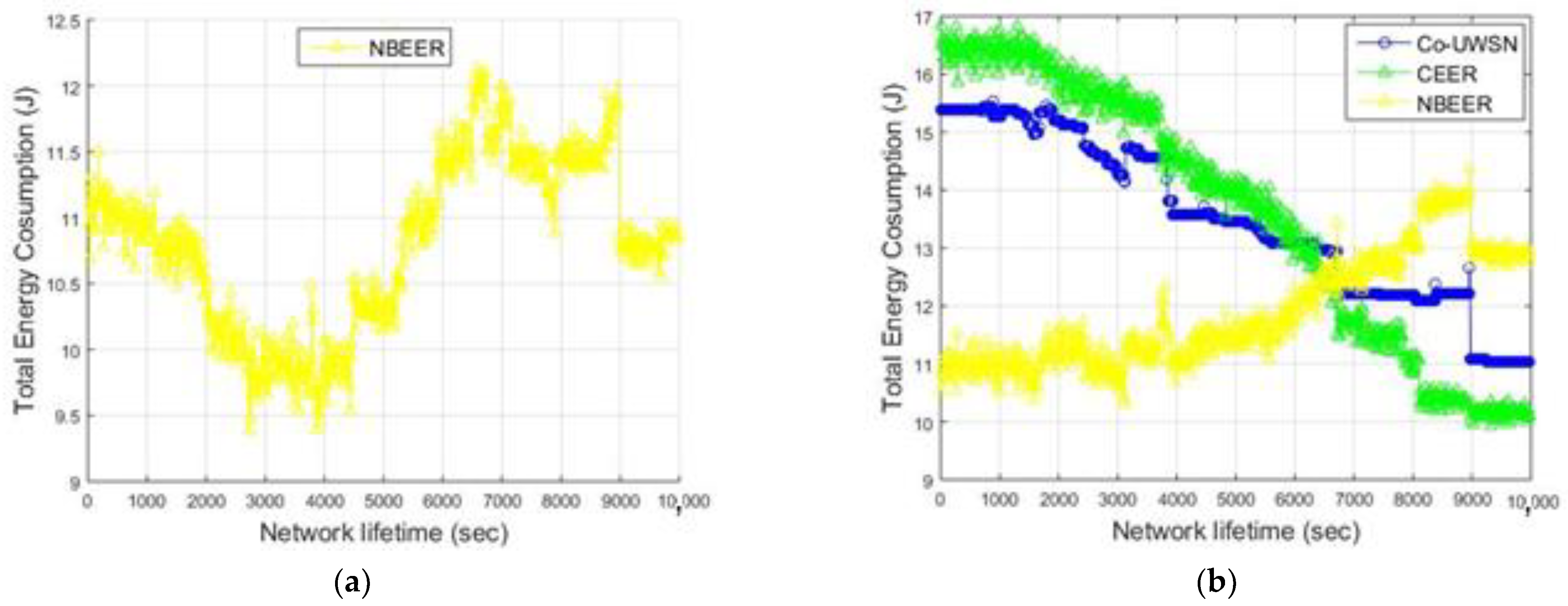
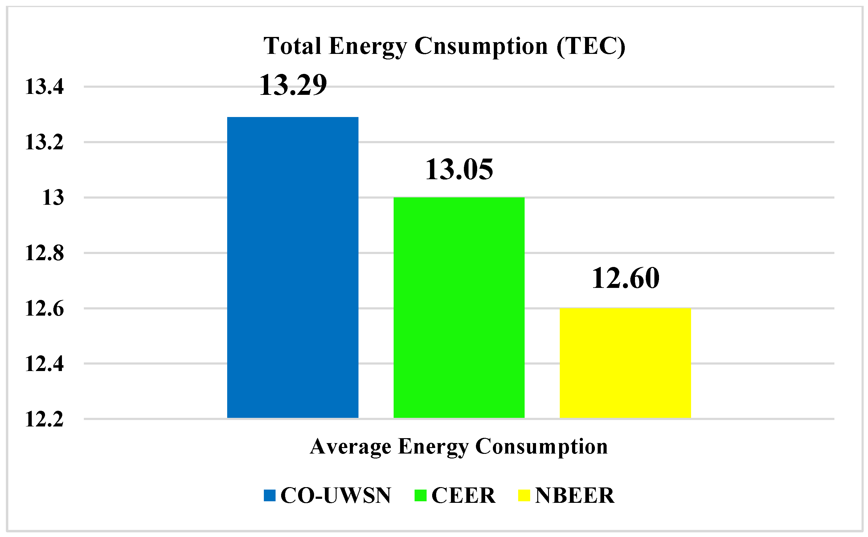
4.2. Total Energy Consumption
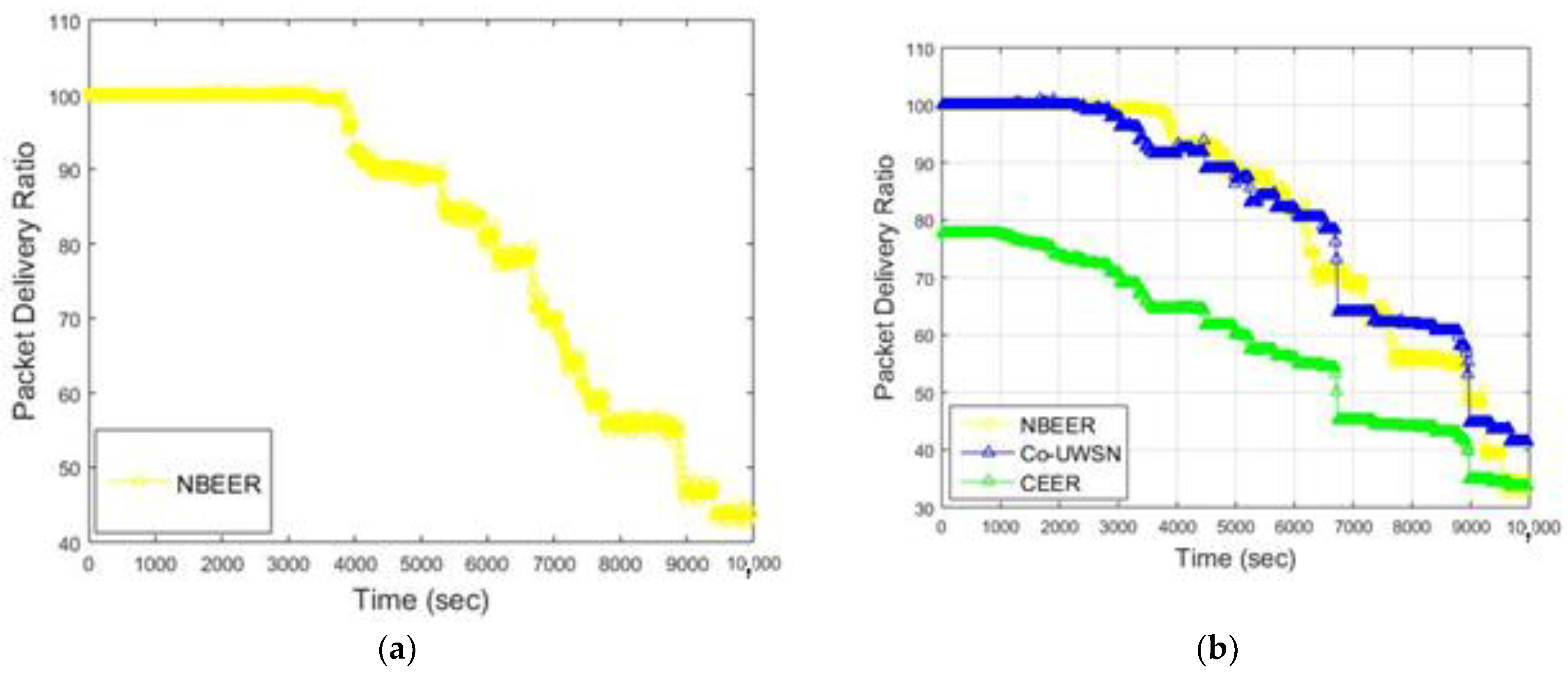
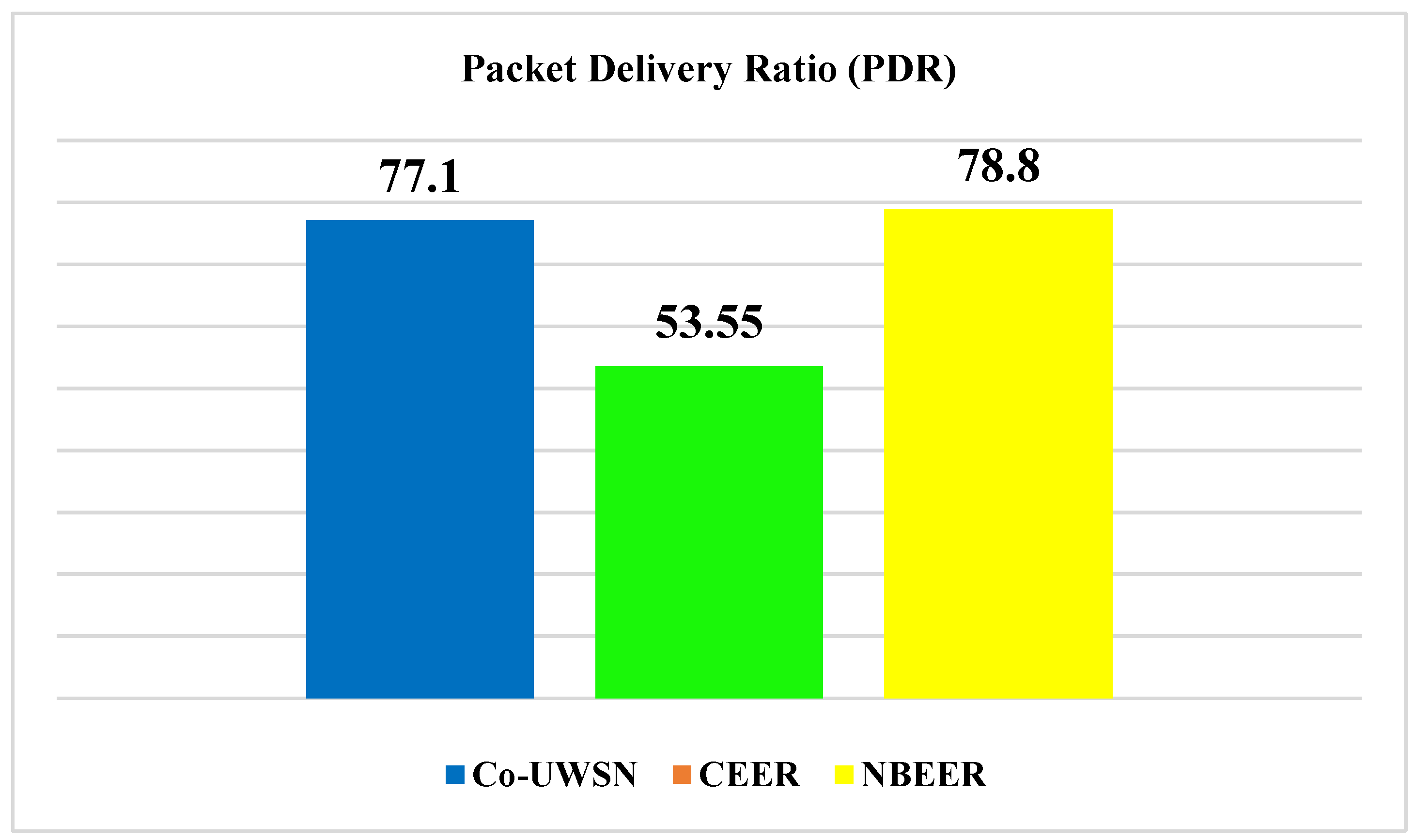
4.3. Packet Delivery Ratio
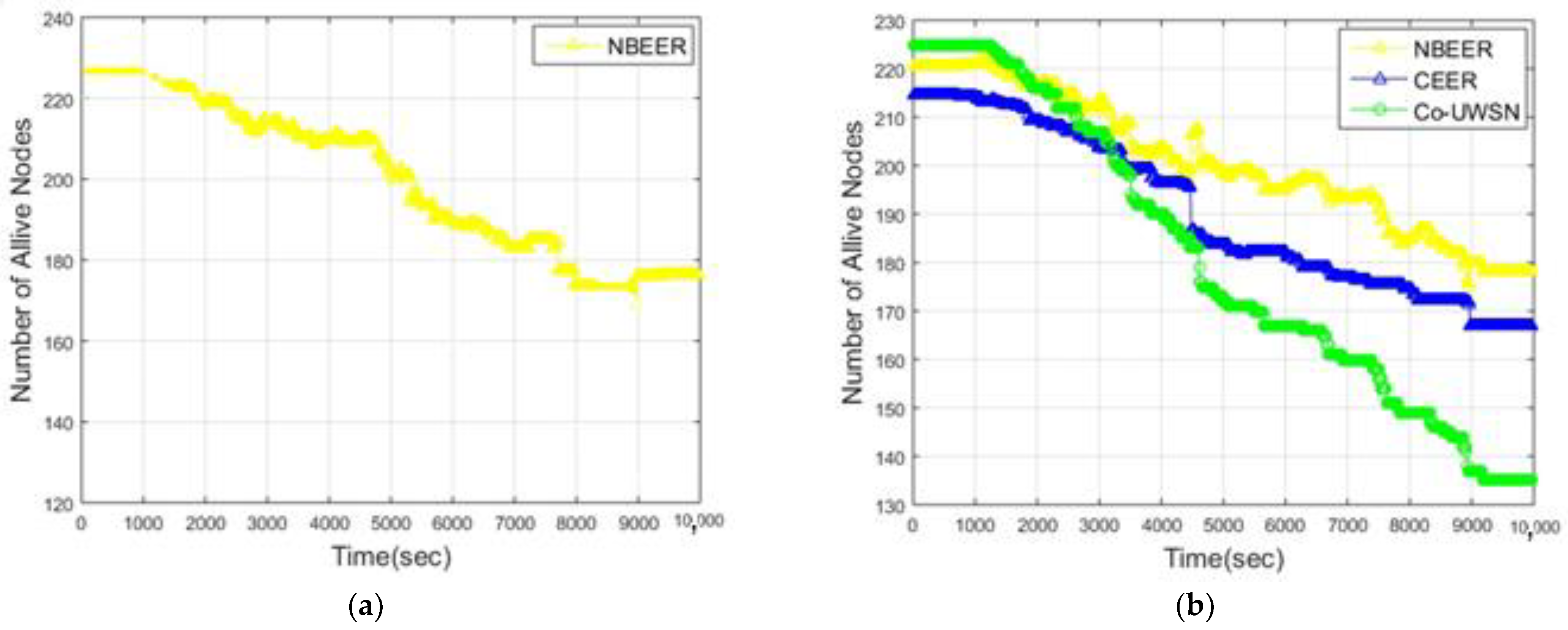
4.4. Number of Alive Nodes
- Iterations of neighboring and Dispersion of Neighbor Head Nodes
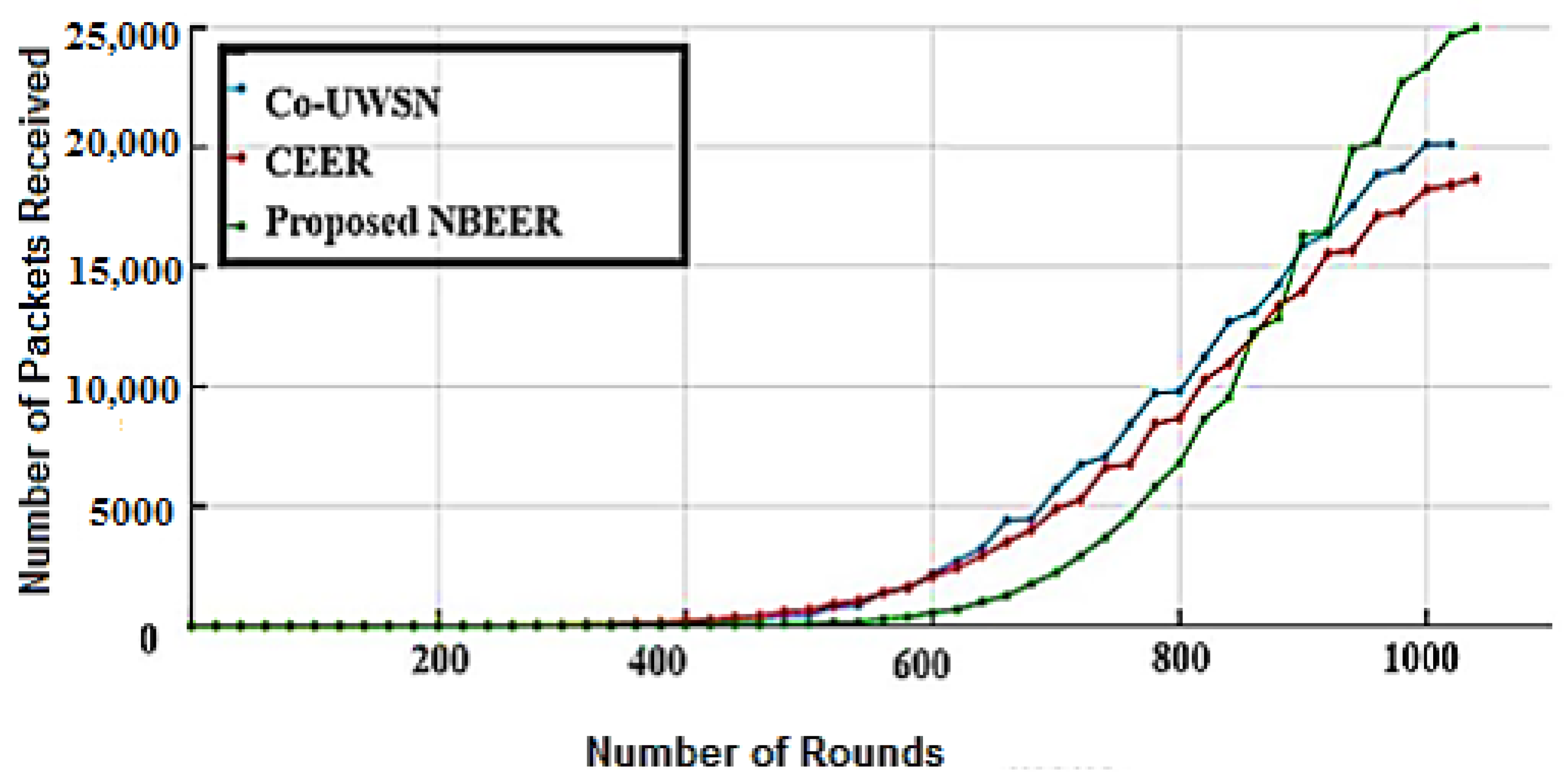
4.5. Number of Packets Received (NPR)
5. Conclusions
Author Contributions
Funding
Data Availability Statement
Conflicts of Interest
References
- Hussain, T.; Rehman, Z.U.; Iqbal, A.; Saeed, K.; Ali, I. Two hop verification for avoiding void hole in underwater wireless sensor network using SM-AHH-VBF and AVH-AHH-VBF routing protocols. Trans. Emerg. Telecommun. Technol. 2020, 31, e3992. [Google Scholar] [CrossRef]
- Rehman, Z.U.; Iqbal, A.; Yang, B.; Hussain, T. Void hole avoidance based on sink mobility and adaptive two hop vector-based forwarding in underwater wireless sensor networks. Wirel. Pers. Commun. 2021, 120, 1417–1447. [Google Scholar] [CrossRef]
- Hussain, A.; Khan, H.U.; Nazir, S.; Ullah, I.; Hussain, T. Taking FANET to Next Level: The Contrast Evaluation of Moth-and-Ant with Bee Ad-hoc Routing Protocols for Flying Ad-hoc Networks. ADCAIJ Adv. Distrib. Comput. Artif. Intell. J. 2021, 10, 321–337. [Google Scholar] [CrossRef]
- Ahmed, M.; Salleh, M.; Channa, M.I. Routing protocols based on node mobility for Underwater Wireless Sensor Network (UWSN): A survey. J. Netw. Comput. Appl. 2017, 78, 242–252. [Google Scholar] [CrossRef]
- Haque, K.F.; Kabir, K.H.; Abdelgawad, A. Advancement of routing protocols and applications of underwater wireless sensor network (UWSN)—A survey. J. Sens. Actuator Netw. 2020, 9, 19. [Google Scholar] [CrossRef] [Green Version]
- Nguyen, N.T.; Le, T.T.; Nguyen, H.H.; Voznak, M. Energy-efficient clustering multi-hop routing protocol in a UWSN. Sensors 2021, 21, 627. [Google Scholar] [CrossRef]
- Kapileswar, N.; Phani Kumar, P. Energy efficient routing in IOT based UWSN using bald eagle search algorithm. Trans. Emerg. Telecommun. Technol. 2022, 33, e4399. [Google Scholar] [CrossRef]
- Eldesouky, E.; Bekhit, M.; Fathalla, A.; Salah, A.; Ali, A. A robust UWSN handover prediction system using ensemble learning. Sensors 2021, 21, 5777. [Google Scholar] [CrossRef]
- Khan, W.; Wang, H.; Anwar, M.S.; Ayaz, M.; Ahmad, S.; Ullah, I. A multi-layer cluster based energy efficient routing scheme for UWSNs. IEEE Access 2019, 7, 77398–77410. [Google Scholar] [CrossRef]
- Ullah, I.; Chen, J.; Su, X.; Esposito, C.; Choi, C. Localization and detection of targets in underwater wireless sensor using distance and angle based algorithms. IEEE Access 2019, 7, 45693–45704. [Google Scholar] [CrossRef]
- Luo, C.; Wang, B.; Cao, Y.; Xin, G.; He, C.; Ma, L. A hybrid coverage control for enhancing UWSN localizability using IBSO-VFA. Ad Hoc Netw. 2021, 123, 102694. [Google Scholar] [CrossRef]
- Basavaraju, P.H.; Lokesh, G.H.; Mohan, G.; Jhanjhi, N.Z.; Flammini, F. Statistical Channel Model and Systematic Random Linear Network Coding Based QoS Oriented and Energy Efficient UWSN Routing Protocol. Electronics 2022, 11, 2590. [Google Scholar] [CrossRef]
- Kumar, R.; Bhardwaj, D. Decision Tree-Based Event Detection Framework for UWSN Routing to Optimize Energy Consumption During Transmission. In Advanced Computing and Intelligent Technologies; Springer: Singapore, 2022; pp. 99–109. [Google Scholar]
- Qin, Q.; Tian, Y.; Wang, X. Three-Dimensional UWSN Positioning Algorithm Based on Modified RSSI Values. Mob. Inf. Syst. 2021, 2021, 5554791. [Google Scholar] [CrossRef]
- Javaid, N.; Ahmad, Z.; Sher, A.; Wadud, Z.; Khan, Z.A.; Ahmed, S.H. Fair energy management with void hole avoidance in intelligent heterogeneous underwater WSNs. J. Ambient. Intell. Humaniz. Comput. 2019, 10, 4225–4241. [Google Scholar] [CrossRef]
- Mahalle, P.N.; Shelar, P.A.; Shinde, G.R.; Dey, N. Applications of UWSN. In The Underwater World for Digital Data Transmission; Springer: Singapore, 2021; pp. 55–64. [Google Scholar]
- Shovon, I.I.; Shin, S. Energy Efficient Routing Protocols for UWSN: A Survey. In Proceedings of the Korea Telecommunications Society Conference, Jeju Island, Republic of Korea, 11–13 December 2022; pp. 275–278. [Google Scholar]
- Pandith, A.M.; Goyal, N. Emerging Data Aggregation State-of-Art Techniques with Comparative Analysis in UWSN. In Proceedings of the 2022 2nd International Conference on Advance Computing and Innovative Technologies in Engineering (ICACITE), Greater Noida, India, 28–29 April 2022; pp. 1829–1833. [Google Scholar]
- Subramani, N.; Mohan, P.; Alotaibi, Y.; Alghamdi, S.; Khalaf, O.I. An efficient metaheuristic-based clustering with routing protocol for underwater wireless sensor networks. Sensors 2022, 22, 415. [Google Scholar] [CrossRef]
- Ismail, A.S.; Wang, X.; Hawbani, A.; Alsamhi, S.; Abdel Aziz, S. Routing protocols classification for underwater wireless sensor networks based on localization and mobility. Wirel. Netw. 2022, 28, 797–826. [Google Scholar] [CrossRef]
- Banothu, R.N.; ArunKumar, A. A Study on FBR Protocol for IoT in underwater Environments. Int. J. Mod. Trends Sci. Technol. 2022, 8, 47–54. [Google Scholar]
- Vignesh, S.R.; Sukumaran, R.; Ponraj, T.S.; Manikandan, T.T.; Saravanan, M. Implementation of Routing Protocol in Underwater Sensor Networks for Energy Harvesting. In Proceedings of the 2022 4th International Conference on Smart Systems and Inventive Technology (ICSSIT), Tirunelveli, India, 20–22 January 2022; pp. 354–361. [Google Scholar]
- Chenthil, T.R.; Jesu Jayarin, P. An energy-efficient distributed node clustering routing protocol with mobility pattern support for underwater wireless sensor networks. Wirel. Netw. 2022, 28, 3367–3390. [Google Scholar] [CrossRef]
- Pradeep, S.; Tapas Bapu, B.R. An efficient energy consumption and delay aware autonomous data gathering routing protocol scheme using a deep learning mobile edge model and beetle antennae search algorithm for underwater wireless sensor network. Concurr. Comput. Pract. Exp. 2022, 34, e6946. [Google Scholar] [CrossRef]
- Zaman, K.; Sun, Z.; Shah, S.M.; Shoaib, M.; Pei, L.; Hussain, A. Driver Emotions Recognition Based on Improved Faster R-CNN and Neural Architectural Search Network. Symmetry 2022, 14, 687. [Google Scholar] [CrossRef]
- Kumar, C.M.; Amin, R.; Brindha, M. SafeCom: Robust mutual authentication and session key sharing protocol for underwater wireless sensor networks. J. Syst. Archit. 2022, 130, 102650. [Google Scholar] [CrossRef]
- Rizvi, H.H.; Khan, S.A.; Enam, R.N.; Naseem, M.; Nisar, K.; Rawat, D.B. Adaptive Energy Efficient Circular Spinning Protocol for Dynamic Cluster Based UWSNs. IEEE Access 2022, 10, 61937–61950. [Google Scholar] [CrossRef]
- Kulla, E.; Shintani, K.; Matsuo, K. Mobility-Aware Narrow Routing Protocol for Underwater Wireless Sensor Networks. In International Conference on Emerging Internetworking, Data & Web Technologies; Springer: Cham, Switzerland, 2022; pp. 245–253. [Google Scholar]
- Hu, Y.; Chen, L.; Sun, Y. The Cooperative-Communication Based Underwater Layered Routing Protocol for Underwater Wireless Sensor Network. Wirel. Pers. Commun. 2022, 125, 3019–3047. [Google Scholar] [CrossRef]
- Sreeraj, A.; Vijayalakshmi, P.; Rajendran, V. A Deep Learning Enabled Software-Defined Radio based Routing Protocol for Underwater Acoustic Sensor Networks. In Proceedings of the 2022 International Conference on Sustainable Computing and Data Communication Systems (ICSCDS), Erode, India, 7–9 April 2022; pp. 28–32. [Google Scholar]
- Sandhiyaa, S.; Gomathy, C. Performance Analysis of Routing Protocol in Underwater Wireless Sensor Network. In Proceedings of the 2022 International Conference on Sustainable Computing and Data Communication Systems (ICSCDS), Erode, India, 7–9 April 2022; pp. 1077–1084. [Google Scholar]
- Shah, S.M.; Sun, Z.; Zaman, K.; Hussain, A.; Shoaib, M.; Pei, L. A driver gaze estimation method based on deep learning. Sensors 2022, 22, 3959. [Google Scholar] [CrossRef]
- Anuradha, D.; Subramani, N.; Khalaf, O.I.; Alotaibi, Y.; Alghamdi, S.; Rajagopal, M. Chaotic search-and-rescue-optimization-based multi-hop data transmission protocol for underwater wireless sensor networks. Sensors 2022, 22, 2867. [Google Scholar] [CrossRef]
- Jatoi, G.M.; Das, B.; Karim, S.; Pabani, J.K.; Krichen, M.; Alroobaea, R.; Kumar, M. Floating Nodes Assisted Cluster-Based Routing for efficient data collection in Underwater Acoustic Sensor Networks. Comput. Commun. 2022, 195, 137–147. [Google Scholar] [CrossRef]
- Ullah, I.; Liu, Y.; Su, X.; Kim, P. Efficient and accurate target localization in underwater environment. IEEE Access 2019, 7, 101415–101426. [Google Scholar] [CrossRef]
- Ahmad, I.; Rahman, T.; Zeb, A.; Khan, I.; Ullah, I.; Hamam, H.; Cheikhrouhou, O. Analysis of security attacks and taxonomy in underwater wireless sensor networks. Wirel. Commun. Mob. Comput. 2021, 2021, 1444024. [Google Scholar] [CrossRef]
- Su, X.; Ullah, I.; Liu, X.; Choi, D. A review of underwater localization techniques, algorithms, and challenges. J. Sens. 2020, 2020, 6403161. [Google Scholar] [CrossRef] [Green Version]
- Hussain, A.; Shah, B.; Hussain, T.; Ali, F.; Kwak, D. Co-DLSA: Cooperative Delay and Link Stability Aware with Relay Strategy Routing Protocol for Flying Ad-Hoc Network. Hum.-Cent. Comput. Inf. Sci. 2022, 12, 1–21. [Google Scholar]
- Shah, S.M.; Hussain, T.; Shah, B.; Ali, F.; Zaman, K.; Kwak, K.S. CEER: Cooperative Energy-Efficient Routing Mechanism for Underwater Wireless Sensor Networks Using Clusters. Comput. Syst. Sci. Eng. 2023, 45, 2587. [Google Scholar] [CrossRef]
- Zaman, K.; Sun, Z.; Hussain, A.; Hussain, T.; Ali, F.; Shah, S.M.; Rahman, H.U. EEDLABA: Energy-Efficient Distance-and Link-Aware Body Area Routing Protocol Based on Clustering Mechanism for Wireless Body Sensor Network. Appl. Sci. 2023, 13, 2190. [Google Scholar] [CrossRef]
- Jovanov, E.; Milenkovic, A.; Otto, C.; De Groen, P.; Johnson, B.; Warren, S.; Taibi, G. A WBAN system for ambulatory monitoring of physical activity and health status: Applications and challenges. In Proceedings of the 2005 IEEE Engineering in Medicine and Biology 27th Annual Conference, Shanghai, China, 17–18 January 2006; pp. 3810–3813. [Google Scholar]
- Hussain, A.; Hussain, T.; Faisal, F.; Ali, I.; Khalil, I.; Nazir, S.; Khan, H.U. DLSA: Delay and Link Stability Aware Routing Protocol for Flying Ad-hoc Networks (FANETs). Wirel. Pers. Commun. 2021, 121, 2609–2634. [Google Scholar] [CrossRef]
- Hussain, T.; Yang, B.; Rahman, H.U.; Iqbal, A.; Ali, F. Improving Source Location Privacy in Social Internet of Things Using a Hybrid Phantom Routing Technique. Comput. Secur. 2022, 123, 102917. [Google Scholar] [CrossRef]


| Ref. | Year | Utilized Technique | Benefits | Limitations |
|---|---|---|---|---|
| [22] | 2022 | A blend of approaches is employed to select forwarder nodes for data transmission, encompassing both single and multipath routing schemes. Various factors, i.e., minor bit error rate (BER), minimum distance to the sink node, and highest residual energy, are considered during the selection process. | Enhanced energy efficiency and dependable packet delivery | Increased latency caused by node collaboration |
| [23] | 2021 | Multipath routing techniques are employed for efficient data transfer among the nodes. | Improved the PDR (packet delivery ratio) | Increases the latency and decreases the reliability |
| [24] | 2020 | The selection of the best forwarder nodes is based on the weight function, and the scheme incorporates the use of the Maximum ratio combining (MRC) technique for improved performance. | Improved the network reliability | More energy consumption |
| [25] | 2019 | Data transmission utilizes the Manhattan and RSSI techniques for enhanced efficiency. | Improved transmission latency and energy construction | More latency due to hierarchical structure |
| [26] | 2019 | Both the collaborative and independent approaches employed the positional data of nodes, considering both proximity and the movement of sinks, to facilitate the propagation of information. | Reduces latency and enhances throughput | Less reliability and high propagation delay |
| [40] | 2018 | The non-cooperative routing scheme employes a designated area of interest. | Improved network lifetime, reliability, and throughput | Data transmission limited to a single random node occurrence |
| [41,42,43] | 2017 | Clustering-based cooperative techniques; nodes cooperate within clusters to send and receive data. | Consumes less energy | A lower packet delivery ratio due to node cooperation |
| Parameter | Value |
|---|---|
| Total Deployed NNS Schemes | 10 |
| Neighbor Node Heads | 12 |
| Primary Energy of Normal Nodes | 22 joules |
| Transmission Range | 250 m |
| Performance Parameter |
|
| Channel and Frequency Type | Acoustic Channel VLF radio waves (3–30 kHz) |
| Frequency Range | 2.412 GHz to 2.472 GHz |
| Number of NNS/Relay Nodes | 20 |
| Packet Size | 512 bytes |
| Parameter | Value |
|---|---|
| Simulator | MATLAB |
| Network Area | 550 m × 450 m × 350 m |
| Number of Deployed Nodes | 250 |
| Total Deployed NNS Schemes | 10 |
| Simulation Time | 1000 s |
| Parameter | Value |
|---|---|
| Primary Energy of Normal Nodes | 22 joules |
| Transmission Range | 250 m |
| Number of NNS/Relay Nodes | 20 |
| Parameter | Value |
|---|---|
| Frequency Range | The frequency range of the channel spans from 2.412 GHz to 2.472 GHz. |
| Packet Size | 512 bytes |
| Parameter | Value |
|---|---|
| Acoustic Propagation Model | Bellhop or Ray Tracing |
| Sound Speed Profile | Empirical or Custom |
| Transmission Frequency | 10 kHz to 50 kHz |
| Transmission Power | 160 dB re 1 μPa @ 1 m |
| E2ED | E2ED | E2ED | E2ED | E2ED | E2D | E2ED | E2ED | E2ED | E2ED | Avg | |
|---|---|---|---|---|---|---|---|---|---|---|---|
| Protocol | After | After | After | after | After | after | After | After | After | After | E2ED |
| 1000 s | 2000 s | 3000 s | 4000 s | 5000 s | 6000 s | 7000 s | 8000 s | 9000 s | 10,000 s | ||
| Co-UWSN | 84.03 | 80.01 | 73.02 | 60.01 | 53.03 | 51.01 | 46.01 | 43.03 | 34.03 | 34.01 | 55.19 |
| CEER | 86 | 82 | 79 | 76 | 75 | 72 | 68 | 70 | 62 | 68 | 73.8 |
| NBEER | 78 | 74 | 68 | 65 | 60 | 57 | 45 | 44 | 42 | 25 | 53.03 |
| TEC | TEC | TEC | TEC | TEC | TEC | TEC | TEC | TEC | TEC | Avg | |
|---|---|---|---|---|---|---|---|---|---|---|---|
| Protocol | after | after | After | after | After | after | after | After | After | After | TEC |
| 1000 s | 2000 s | 3000 s | 4000 s | 5000 s | 6000 s | 7000 s | 8000 s | 9000 s | 10,000 s | ||
| Co-UWSN | 17.35 | 15.0 | 14.19 | 12.98 | 12.68 | 12.0 | 11.48 | 10.01 | 9.95 | 9.79 | 13.29 |
| CEER | 16.93 | 15.62 | 11.26 | 9.54 | 8.31 | 7.113 | 6.56 | 6.145 | 5.93 | 4.93 | 13.15 |
| NBEER | 16 | 16.2 | 16.3 | 13 | 12.0 | 11.9 | 10.8 | 9.07 | 8.15 | 8.01 | 12.60 |
| PDR | PDR | PDR | PDR | PDR | PDR | PDR | PDR | PDR | PDR | Avg | |
|---|---|---|---|---|---|---|---|---|---|---|---|
| Protocol | After | After | After | After | After | After | after | after | After | After | PDR |
| 1000 s | 2000 s | 3000 s | 4000 s | 5000 s | 6000 s | 7000 s | 8000 s | 9000 s | 10,000 s | ||
| Co-UWSN | 100 | 100 | 98 | 90 | 88 | 80 | 65 | 61 | 57 | 42 | 77.1 |
| CEER | 99.51 | 95.51 | 78.95 | 65.22 | 48.78 | 41.88 | 38.94 | 24.21 | 24.21 | 22.34 | 53.55 |
| NBEER | 100 | 100 | 100 | 93 | 91 | 82 | 72 | 58 | 56 | 36 | 78.8 |
| First Node Dies at s | Alive Nodes | Alive Nodes | Alive Nodes | Alive Nodes | Alive Nodes | Alive Nodes | Alive Nodes | Alive Nodes | Alive Nodes | Alive Nodes | Average Alive Nodes | |
|---|---|---|---|---|---|---|---|---|---|---|---|---|
| Protocol | After | After | After | After | After | After | After | After | After | After | ||
| 1000 s | 2000 s | 3000 s | 4000 s | 5000 s | 6000 s | 7000 s | 8000 s | 9000 s | 10,000 s | |||
| Co-UWSN | 551 | 225 | 217 | 207 | 191 | 170 | 168 | 160 | 150 | 139 | 135 | 176.2 |
| CEER | 529 | 215 | 209 | 204 | 198 | 182 | 180 | 178 | 172 | 168 | 167 | 187.3 |
| NBEER | 633 | 220 | 218 | 212 | 203 | 198 | 195 | 192 | 184 | 181 | 180 | 198.3 |
Disclaimer/Publisher’s Note: The statements, opinions and data contained in all publications are solely those of the individual author(s) and contributor(s) and not of MDPI and/or the editor(s). MDPI and/or the editor(s) disclaim responsibility for any injury to people or property resulting from any ideas, methods, instructions or products referred to in the content. |
© 2023 by the authors. Licensee MDPI, Basel, Switzerland. This article is an open access article distributed under the terms and conditions of the Creative Commons Attribution (CC BY) license (https://creativecommons.org/licenses/by/4.0/).
Share and Cite
Shah, S.M.; Sun, Z.; Zaman, K.; Hussain, A.; Ullah, I.; Ghadi, Y.Y.; Khan, M.A.; Nasimov, R. Advancements in Neighboring-Based Energy-Efficient Routing Protocol (NBEER) for Underwater Wireless Sensor Networks. Sensors 2023, 23, 6025. https://doi.org/10.3390/s23136025
Shah SM, Sun Z, Zaman K, Hussain A, Ullah I, Ghadi YY, Khan MA, Nasimov R. Advancements in Neighboring-Based Energy-Efficient Routing Protocol (NBEER) for Underwater Wireless Sensor Networks. Sensors. 2023; 23(13):6025. https://doi.org/10.3390/s23136025
Chicago/Turabian StyleShah, Sayyed Mudassar, Zhaoyun Sun, Khalid Zaman, Altaf Hussain, Inam Ullah, Yazeed Yasin Ghadi, Muhammad Abbas Khan, and Rashid Nasimov. 2023. "Advancements in Neighboring-Based Energy-Efficient Routing Protocol (NBEER) for Underwater Wireless Sensor Networks" Sensors 23, no. 13: 6025. https://doi.org/10.3390/s23136025