Wideband Array Signal Processing with Real-Time Adaptive Interference Mitigation

 , , ,
, , , 
Abstract
:1. Introduction
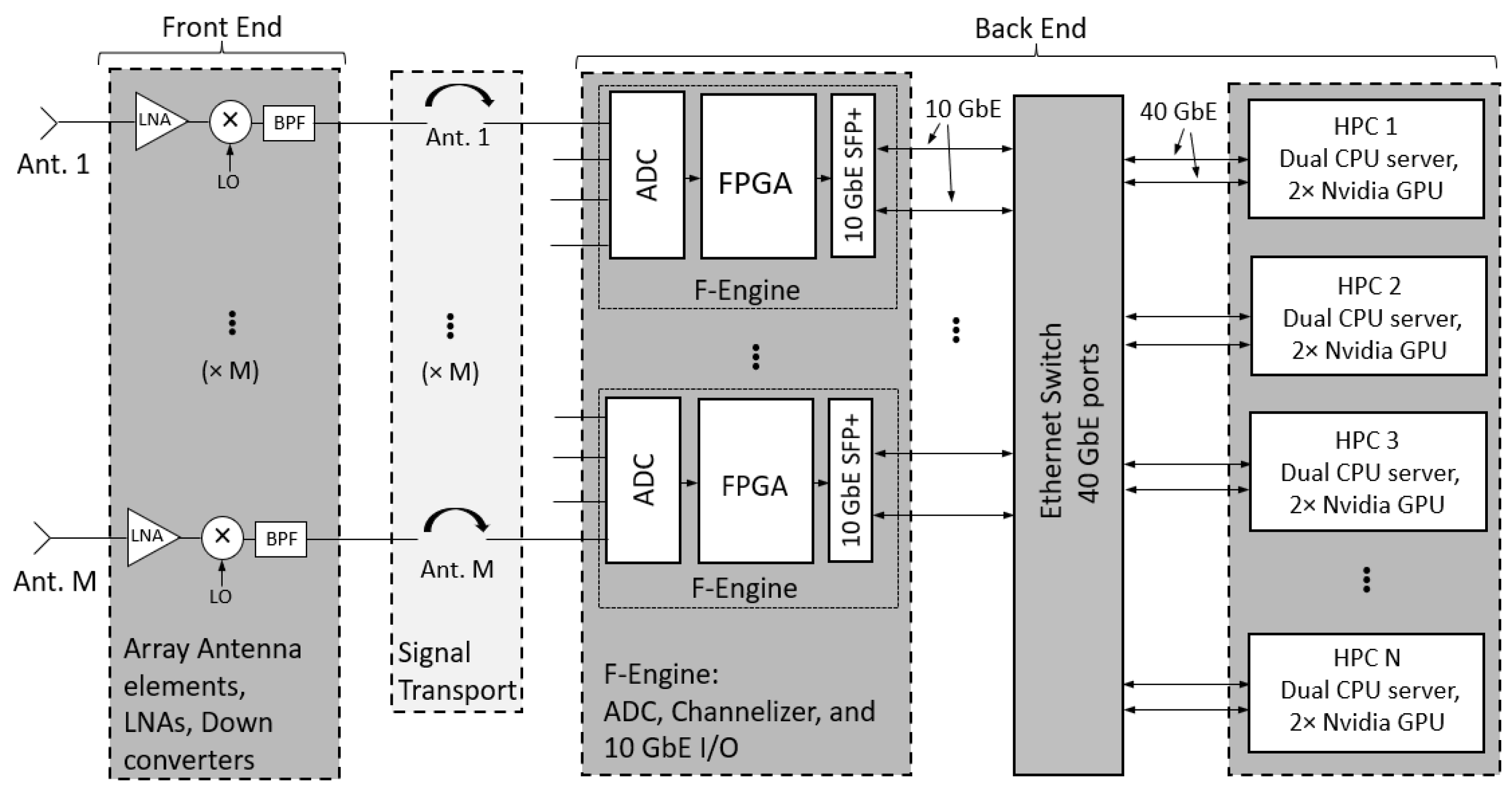
2. System Overview
3. Subspace Projection for Interference Cancellation
4. Experimental Results
5. Conclusions
Author Contributions
Funding
Institutional Review Board Statement
Informed Consent Statement
Data Availability Statement
Conflicts of Interest
References
- de Souza, L.; Bunton, J.D.; Campbell-Wilson, D.; Cappallo, R.J.; Kincaid, B. A Radio Astronomy Correlator Optimized for the Xilinx Virtex-4 SX FPGA. In Proceedings of the 2007 International Conference on Field Programmable Logic and Applications, Amsterdam, The Netherlands, 27–29 August 2007; pp. 62–67. [Google Scholar] [CrossRef]
- Parsons, A.; Backer, D.; Siemion, A.; Chen, H.; Werthimer, D.; Droz, P.; Filiba, T.; Manley, J.; McMahon, P.; Parsa, A.; et al. A Scalable Correlator Architecture Based on Modular FPGA Hardware, Reuseable Gateware, and Data Packetization. Publ. Astron. Soc. Pac. 2008, 120, 1207. [Google Scholar] [CrossRef] [Green Version]
- Burnett, M.C. Advancements in Radio Astronomical Array Processing: Digital Back End Development and Interferometric Array Interference Mitigation. Master’s Thesis, Brigham Young University, Provo, UT, USA, 2017. [Google Scholar]
- MacMahon, D.H.E.; Price, D.C.; Lebofsky, M.; Siemion, A.P.V.; Croft, S.; DeBoer, D.; Enriquez, J.E.; Gajjar, V.; Hellbourg, G.; Isaacson, H.; et al. The Breakthrough Listen Search for Intelligent Life: A Wideband Data Recorder System for the Robert C. Byrd Green Bank Telescope. Publ. Astron. Soc. Pac. 2018, 130, 044502. [Google Scholar] [CrossRef] [Green Version]
- Kocz, J.; Greenhill, L.; Barsdell, B.; Price, D.; Bernardi, G.; Bourke, S.; Clark, M.; Craig, J.; Dexter, M.; Dowell, J.; et al. Digital signal processing using stream high performance computing: A 512-input broadband correlator for radio astronomy. J. Astron. Instrum. 2015, 4, 1550003. [Google Scholar] [CrossRef] [Green Version]
- Price, D.C.; Kocz, J.; Bailes, M.; Greenhill, L.J. Introduction to the special issue on digital signal processing in radio astronomy. J. Astron. Instrum. 2016, 5, 1602002. [Google Scholar] [CrossRef]
- Manley, J. A Scalable Packetised Radio Astronomy Imager. Master’s Thesis, University of Cape Town, Cape Town, South Africa, 2015. [Google Scholar]
- Hickish, J.; Beasley, T.; Bower, G.; Burke-Spolaor, S.; Croft, S.; DeBoer, D.; Demorest, P.; Diamond, B.; Gajjar, V.; Law, C.; et al. Commensal, Multi-user Observations with an Ethernet-based Jansky Very Large Array. Bull. AAS 2019, 51, 1–16. [Google Scholar]
- Price, D.; Greenhill, L.; Fialkov, A.; Bernardi, G.; Garsden, H.; Barsdell, B.; Kocz, J.; Anderson, M.; Bourke, S.; Craig, J.; et al. Design and characterization of the Large-aperture Experiment to Detect the Dark Age (LEDA) radiometer systems. Mon. Not. R. Astron. Soc. 2018, 478, 4193–4213. [Google Scholar] [CrossRef] [Green Version]
- Pingel, N.; Pisano, D.; Ruzindana, M.; Burnett, M.; Rajwade, K.; Black, R.; Jeffs, B.; Warnick, K.; Lorimer, D.; Roshi, D.A.; et al. Commissioning the HI Observing Mode of the Beam Former for the Cryogenically Cooled Focal L-band Array for the GBT (FLAG). Astron. J. 2021, 161, 163. [Google Scholar] [CrossRef]
- Burnett, M.C.; Kunzler, J.; Nygaard, E.; Jeffs, B.D.; Warnick, K.F.; Campbell, D.; Cortes-Medellin, G.; Parshley, S.; Vishwas, A.; Perillat, P.; et al. Design and Development of a Wide-Field Fully Cryogenic Phased Array Feed for Arecibo. In Proceedings of the 2020 XXXIIIrd General Assembly and Scientific Symposium of the International Union of Radio Science, Rome, Italy, 29 August–5 September 2020; IEEE: Piscataway, NJ, USA, 2020; pp. 1–4. [Google Scholar]
- Ellingson, S.W. Introduction to special section on mitigation of radio frequency interference in radio astronomy. Radio Sci. 2005, 40. [Google Scholar] [CrossRef] [Green Version]
- Nagel, J.R.; Warnick, K.F.; Jeffs, B.D.; Fisher, J.R.; Bradley, R. Experimental verification of radio frequency interference mitigation with a focal plane array feed. Radio Sci. 2007, 42, 1–8. [Google Scholar] [CrossRef]
- Hellbourg, G.; Chippendale, A.; Kesteven, M.J.; Jeffs, B.D. Reference antenna-based subspace tracking for RFI mitigation in radio astronomy. In Proceedings of the 2014 IEEE Global Conference on Signal and Information Processing (GlobalSIP), Atlanta, GA, USA, 3–5 December 2014; IEEE: Piscataway, NJ, USA, 2014; pp. 1286–1290. [Google Scholar]
- Burnett, M.C.; Jeffs, B.D.; Black, R.A.; Warnick, K.F. Subarray processing for projection-based RFI mitigation in radio astronomical interferometers. Astron. J. 2018, 155, 146. [Google Scholar] [CrossRef]
- Querol, J.; Perez, A.; Camps, A. A review of RFI mitigation techniques in microwave radiometry. Remote Sens. 2019, 11, 3042. [Google Scholar] [CrossRef] [Green Version]
- Lin, Z.; Lin, M.; Champagne, B.; Zhu, W.P.; Al-Dhahir, N. Secrecy-Energy Efficient Hybrid Beamforming for Satellite-Terrestrial Integrated Networks. IEEE Trans. Commun. 2021, 69, 6345–6360. [Google Scholar] [CrossRef]
- Lin, Z.; Lin, M.; de Cola, T.; Wang, J.B.; Zhu, W.P.; Cheng, J. Supporting IoT with Rate-Splitting Multiple Access in Satellite and Aerial-Integrated Networks. IEEE Internet Things J. 2021, 8, 11123–11134. [Google Scholar] [CrossRef]
- An, K.; Lin, M.; Ouyang, J.; Zhu, W.P. Secure Transmission in Cognitive Satellite Terrestrial Networks. IEEE J. Sel. Areas Commun. 2016, 34, 3025–3037. [Google Scholar] [CrossRef]
- Ruzindana, M.W.; Burnett, M.C.; Kunzler, J.W.; Marsh, D.M.; Lyman, K.; Evans, K.; Whipple, A.; Warnick, K.F.; Jeffs, B.D. Real-time Signal Processing with FPGAs and GPUs for Wideband Interference-resilient Communications. In Proceedings of the 2021 IEEE USNC-URSI Radio Science Meeting, Singapore, 4–10 December 2021; IEEE: Piscataway, NJ, USA, 2021; pp. 1–2. [Google Scholar]
- Ruzindana, M.W. Digital Signal Processing Algorithms Implemented on Graphics Processing Units and Software Development for Phased Array Receiver Systems. Ph.D. Thesis, Brigham Young University, Provo, UT, USA, 2021. [Google Scholar]
- Marsh, D.M. Phased Array Digital Beamforming Algorithms and Applications. Master’s Thesis, Brigham Young University, Provo, UT, USA, 2019. [Google Scholar]
- DeBoer, D.R.; Parsons, A.R.; Aguirre, J.E.; Alexander, P.; Ali, Z.S.; Beardsley, A.P.; Bernardi, G.; Bowman, J.D.; Bradley, R.F.; Carilli, C.L.; et al. Hydrogen Epoch of Reionization Array (HERA). Publ. Astron. Soc. Pac. 2017, 129, 045001. [Google Scholar] [CrossRef]
- Hickish, J.; Abdurashidova, Z.; Ali, Z.; Buch, K.D.; Chaudhari, S.C.; Chen, H.; Dexter, M.; Domagalski, R.S.; Ford, J.; Foster, G.; et al. A Decade of Developing Radio-Astronomy Instrumentation using CASPER Open-Source Technology. J. Astron. Instrum. 2016, 5, 1641001–1641012. [Google Scholar] [CrossRef] [Green Version]
- Macmahon, D. HASHPIPE. 2018. Available online: https://github.com/david-macmahon/hashpipe (accessed on 20 January 2023).
- Timcenko, V.; Djordjevic, B. The comprehensive performance analysis of striped disk array organizations—RAID-0. In Proceedings of the 2013 International Conference on Information Systems and Design of Communication, Lisbon, Portugal, 11–12 July 2013; pp. 113–116. [Google Scholar]
- Hellbourg, G. Subspace smearing and interference mitigation with array radio telescopes. In Proceedings of the 2015 IEEE Signal Processing and Signal Processing Education Workshop (SP/SPE), Salt Lake City, UT, USA, 9–12 August 2015; pp. 278–282. [Google Scholar] [CrossRef]
- Landon, J.; Jeffs, B.D.; Warnick, K.F. Model-Based Subspace Projection Beamforming for Deep Interference Nulling. IEEE Trans. Signal Process. 2012, 60, 1215–1228. [Google Scholar] [CrossRef]


Disclaimer/Publisher’s Note: The statements, opinions and data contained in all publications are solely those of the individual author(s) and contributor(s) and not of MDPI and/or the editor(s). MDPI and/or the editor(s) disclaim responsibility for any injury to people or property resulting from any ideas, methods, instructions or products referred to in the content. |
© 2023 by the authors. Licensee MDPI, Basel, Switzerland. This article is an open access article distributed under the terms and conditions of the Creative Commons Attribution (CC BY) license (https://creativecommons.org/licenses/by/4.0/).
Share and Cite
Whipple, A.; Ruzindana, M.W.; Burnett, M.C.; Kunzler, J.W.; Lyman, K.; Jeffs, B.D.; Warnick, K.F. Wideband Array Signal Processing with Real-Time Adaptive Interference Mitigation. Sensors 2023, 23, 6584. https://doi.org/10.3390/s23146584
Whipple A, Ruzindana MW, Burnett MC, Kunzler JW, Lyman K, Jeffs BD, Warnick KF. Wideband Array Signal Processing with Real-Time Adaptive Interference Mitigation. Sensors. 2023; 23(14):6584. https://doi.org/10.3390/s23146584
Chicago/Turabian StyleWhipple, Adam, Mark W. Ruzindana, Mitchell C. Burnett, Jakob W. Kunzler, Kayla Lyman, Brian D. Jeffs, and Karl F. Warnick. 2023. "Wideband Array Signal Processing with Real-Time Adaptive Interference Mitigation" Sensors 23, no. 14: 6584. https://doi.org/10.3390/s23146584
APA StyleWhipple, A., Ruzindana, M. W., Burnett, M. C., Kunzler, J. W., Lyman, K., Jeffs, B. D., & Warnick, K. F. (2023). Wideband Array Signal Processing with Real-Time Adaptive Interference Mitigation. Sensors, 23(14), 6584. https://doi.org/10.3390/s23146584